I've been enamored with Boston Dynamics' robots since first seeing them more than 10 years ago but really started thinking about making my own when inspired by James Bruton's OpenDog project on youtube. His project rationalized a few concepts that made the build feasible for me and I began thinking of how to make a quadruped robot with cost as my primary consideration. I had the time so I began designing and printing anything that I could. This resulted in picking a gear-motor and designing a recirculating ball screw actuator and printed bearings based on readily available and cheap 1/8" and 6mm balls.
More recently, I've run into an issue reliably reading my chosen mechanical encoder so I'm moving to AS5600 magnet encoders at each joint. While a bit of a cost impact, this should solve not only the noisy mechanical encoder but several other know issues.
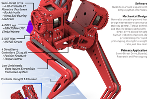
My quadruped utilizes (12) 100-150mm typical recirculating ball screw actuators of my own design. They contain minimum and maximum travel limit switches with provisions for direct geared encoder. The ball screw actuators use ⅛” delrin bearing balls with a 4.5mm pitch, 12mm pitch diameter recirculating ball screw with a 11/20 tooth printed T5 belt reduction. I chose a 550 rpm @ 12V gearmotor which yields ~23mm/s actuation speed at no load. The leg joints utilize the same ⅛” bearings while the shoulder joints use 6mm plastic bearings due to the higher moment loads. All joint positions are measured with AMS AS5600 magnet angle sensors. The primary controller is an ESP8266 chosen for wifi connectivity and computation capacity. For expanded IO; (2) STM32F103 capture (6) actuators and magnet angle joint position sensors front and rear respectively. The microcontrollers and AS5600 sensors communicate through a multiple bus I2C network. After reviewing several options I chose the Blynk app as the control interface. Blynk offers a very flexible, feature rich, and simple to implement method to pass many control signals by wifi to the ESP8266 mcu. ESP8266 receives all Blynk control signals then completes all inverse kinematic valuations that generate joint angle positions. These position setpoints are sent to the respective STM32 which handle all of the actuator PID positioning.
Step file is included for assembly clarification along with an Autodesk Share for 3D viewing. Let me know if there was an issue with the batch STL export.
At this point I have a basic walk algorithm functioning but would be looking for input or considerations for improvements.
https://photos.app.goo.gl/iCJC9nnnxcGjZ2Gt6
https://photos.app.goo.gl/EtS7ruEK7NCBSksc9
Google Photo Album of build:
https://photos.app.goo.gl/aTyLjL6e3BeYmFEd8
Autodesk Share:
https://autode.sk/3gKsfRK
BOM:
https://docs.google.com/spreadsheets/d/10X3TqQt-P1oyN4yVSh_vk_2UqLmrrHuKHLQsvfdMOtE/edit?usp=sharing
Source Code:
https://github.com/DesignCell/RoboDog_ESP8266_Controller.git
https://github.com/DesignCell/RoboDog_STM32_IO.git


 Darren V Levine
 Antonio Regueira
 Maximiliano Palay
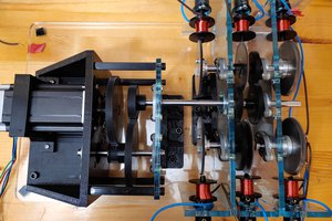
 TheMixedSignal
Hi, first, your project is very cool. I don't really figured out where you are in the advancements. Actually only shoulders move, that's rights ?