mircemk
The device is very simple to build and contains only a few components:
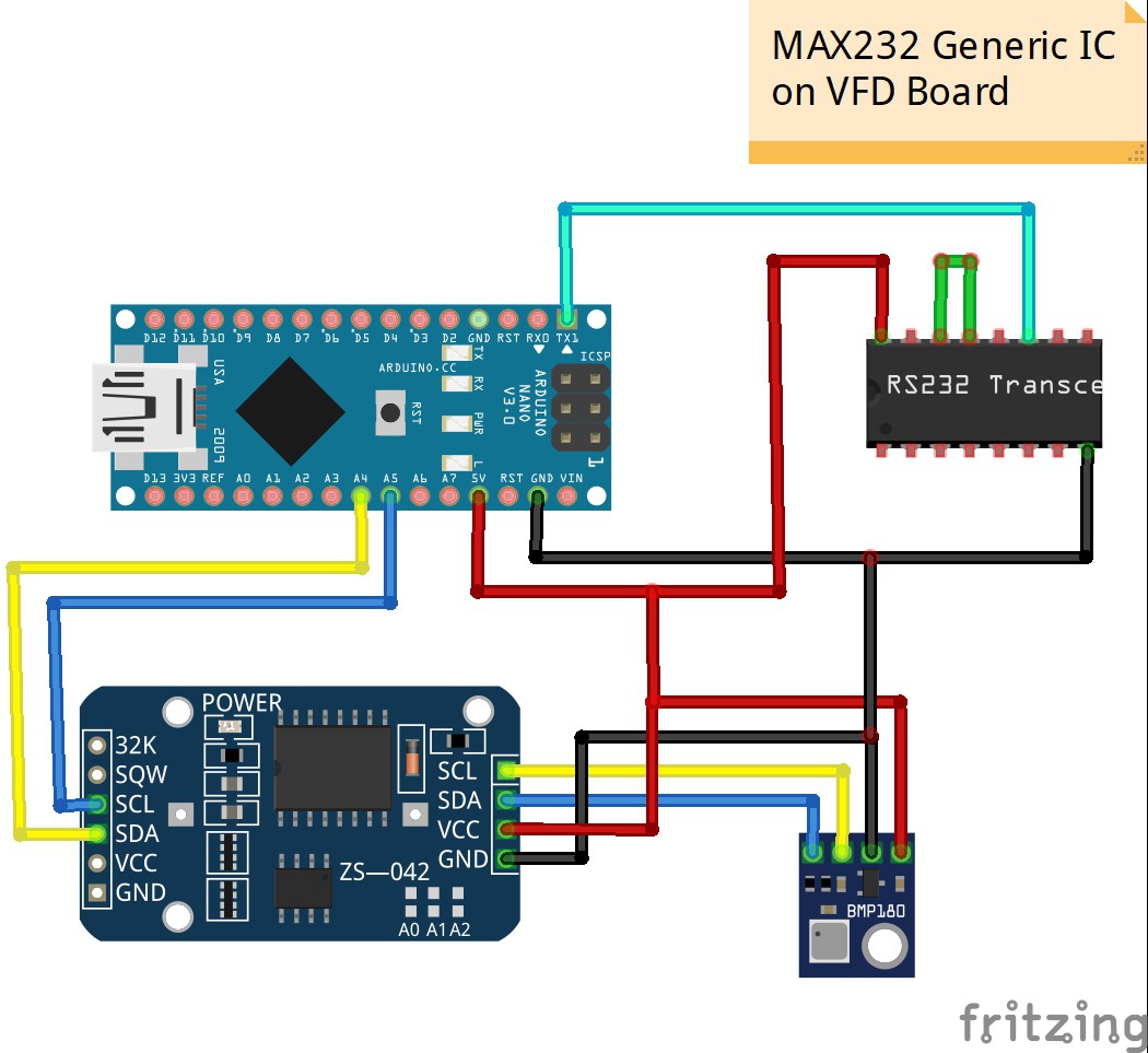
- Arduino Nano microcontroller
- BMP180 barometric sensor, which is mounted outside the box for more accurate temperature measurement
- DS3231 realtime clock module
- and POS customer VFD display
In this video I will describe how to connect any unknown serial VFD display to the Arduino microcontroller, where the text from the serial monitor is shown on the display.
----------------------------------------
Get 10 PCBs only $5
https://www.pcbway.com/
---------------------------------------
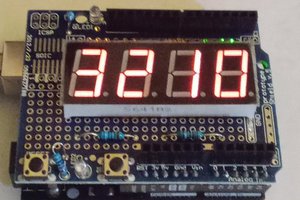
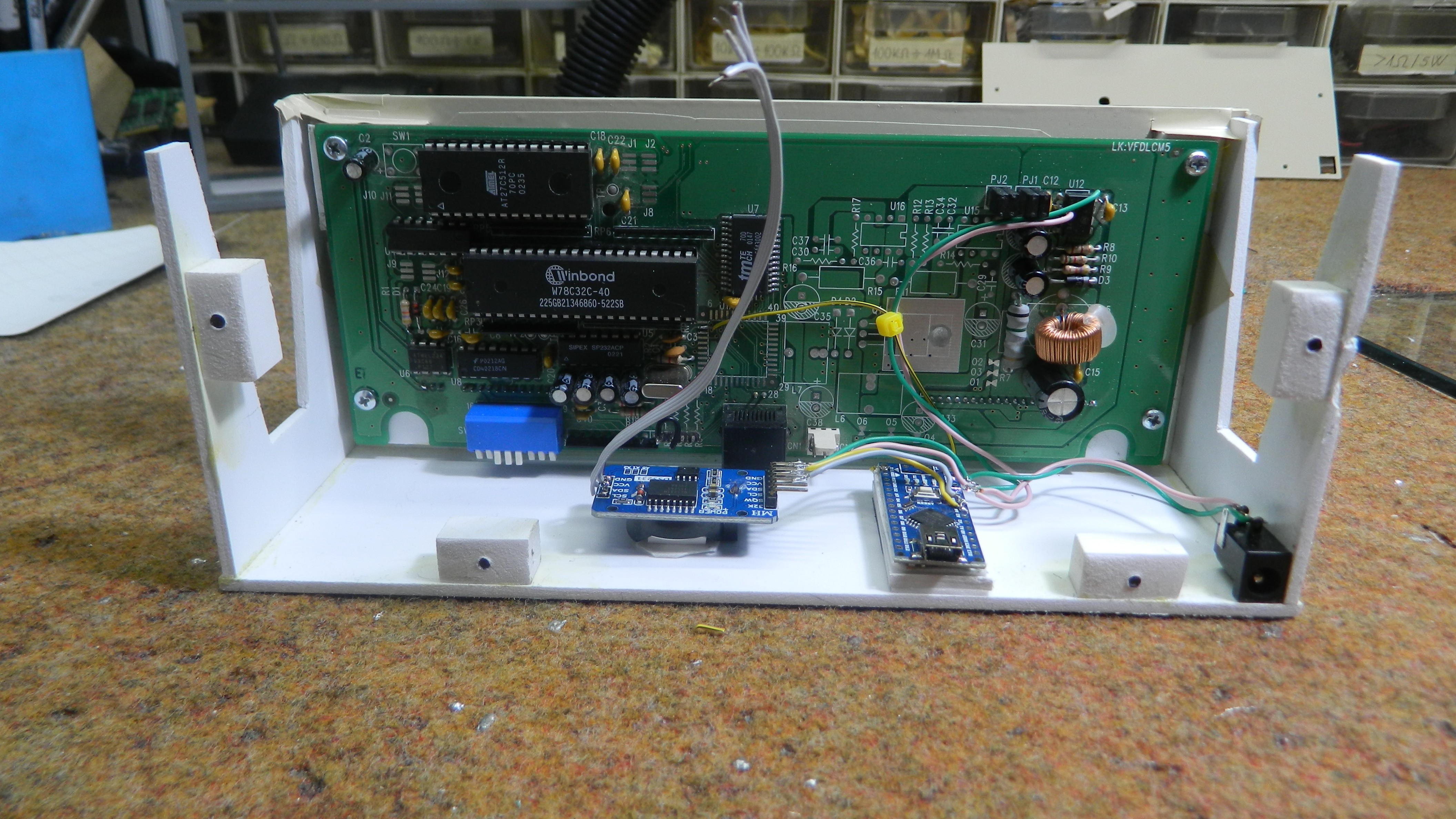
First we need to connect it to the power supply. For this purpose I reviewed the datasheets for most chips on the board and it is seen that the supply voltage should be 5V. It was easiest and safest to solder the power cords directly to pin 4 (Gnd) and pin 6 (Vcc) of MC 34063 chip. After connecting the power supply, the basic information appears on the display, and we are most interested in Baud Rate, who in this case is 4800.
Next we need to find out how this display will communicate with the Arduino. Almost every serial display has RS-232 line driver/receiver chip usually max 232 or equivalent. Specifically in this case it is SIPEX SP232 ACP. The datasheets show that the TTL input to the circuit is pin 11. We also need to shorten pins 14 and 13,Transmit data and Receive data. Now we need to connect the TX output from the Arduino to the TTL input of the MAX232 chip pin11. In this case, everything we see on the Arduino serial monitor will be displayed on the VFD display.
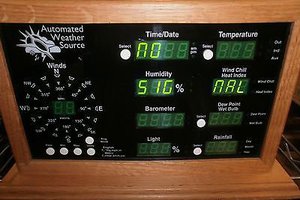
For example I made a simple weather station with BMP180 which also contains a clock with DS3231 board. As we can see, the information on the serial monitor should be in one row , and not longer than 40 characters. We do this in the code with the help of Serial.print and Serial.println commands and with a combination of spaces. Finally, the device is mounted in a suitable box made of 5mm PVC board and coated with colored wallpaper.
 Hulk
Hulk
 electronicsworkshops