 Stefan Wagner
Basic Principle
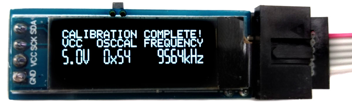
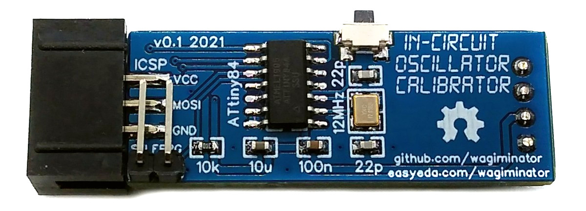
To carry out the calibration, a program is first uploaded to the target MCU using the integrated In-Circuit Serial Programmer (ICSP). This program applies an oscillating signal with half the clock frequency to the MOSI pin of the target MCU. Since the fuses were previously set so that the target MCU clock runs with a prescaler of 8, a signal with 1/16 of the oscillator frequency is applied to that pin. This frequency is measured by the timers of the ATtiny84 and compared with the target value. The oscillator calibration value (OSCCAL) is then adjusted accordingly and written into the EEPROM of the target MCU. This value is in turn read by the target MCU and written to its OSCCAL register. This process is repeated until the OSCCAL value, which leads to the lowest frequency deviation, has been found.
The current firmware version supports the following MCUs:
| MCU | OSC Frequency |
|---|---|
| ATtiny13 (A) | 9.6 MHz |
| ATtiny24/44/84 (A) | 8 MHz |
| ATtiny25/45/85 | 8 MHz |
| ATmega8 (A) | 8 MHz |
Operating Instructions
Warning: The firmware on the target MCU will be erased!
- Connect the TinyICOC to the ICSP header of the target board.
- Provide power to the target board.
- Push the button.
After the calibration process, the optimal OSCCAL value remains in memory address 0 of the EEPROM and can continue to be used. To do this, program the EEFUSE to preserve EEPROM memory through the chip erase cycle, otherwise the OSCCAL value will be lost after uploading new firmware. Your code should then contain the following function:
#include <avr/eeprom.h>
void readOSCCAL(void) {
    uint8_t value = eeprom_read_byte(0);
    if (value < 0xFF) OSCCAL = value;
}
Of course, the OSCCAL value can also be set directly without the EEPROM. Remember that the OSCCAL value is displayed in hexadecimal.
OSCCAL = 0x66;

 Ced
Ced
 Marcel van Kervinck
 kodera2t
i'm having trouble tracking down what "AVR" stands for...