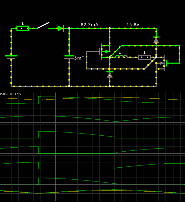
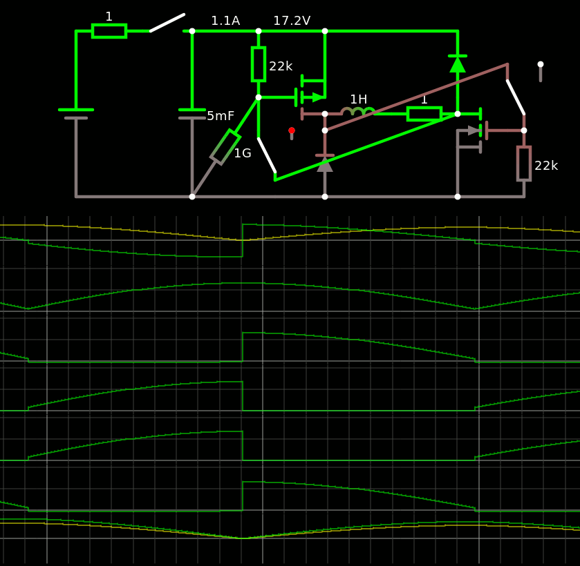
• Self starting !

    Yann Guidon / YGDES05/05/2021 at 05:10 0 comments

    So I was trying to make a "regulator" and I noticed it seemed to start-up nicely as well.

    The trick is to use one of the feedback signals to generate a down pulse through a dumb charge pump. The P MOSFET conducts for a while (see the lower trace) and the potentiometer handles the RC constant. Apparently 100K and 100nF are about good for a sustained oscillation, but higher voltages can be reached very easily with more than 200K.

    The period is still determined by the tank capacitor.

    The 1G resistor is here for stability of the simulation, it's purely symbolic and otherwise useless...

    And the sim link.

  • Resistor is futile

    Yann Guidon / YGDES05/05/2021 at 04:09 0 comments

    It looks like I can reduce the parts count even further.

    Now it's 2 MOSFET, 2 diodes and 1 capacitor.

    It looks more like a classic oscillator to me now...

    The link

    I am tempted to replace the diodes with MOSFETs to increase the efficiency but that would complicate the design since they would have to work when the capacitor is discharged.

    Startup is still a problem. I can make it start to oscillate from a low voltage but it relies on transients, to make the coil react.

  • Self-oscillating

    Yann Guidon / YGDES05/05/2021 at 02:54 0 comments

    I had a weird idea : cross-link the gates of the MOSFETs to the output of the others.

    Falstad says it should oscillate freely !

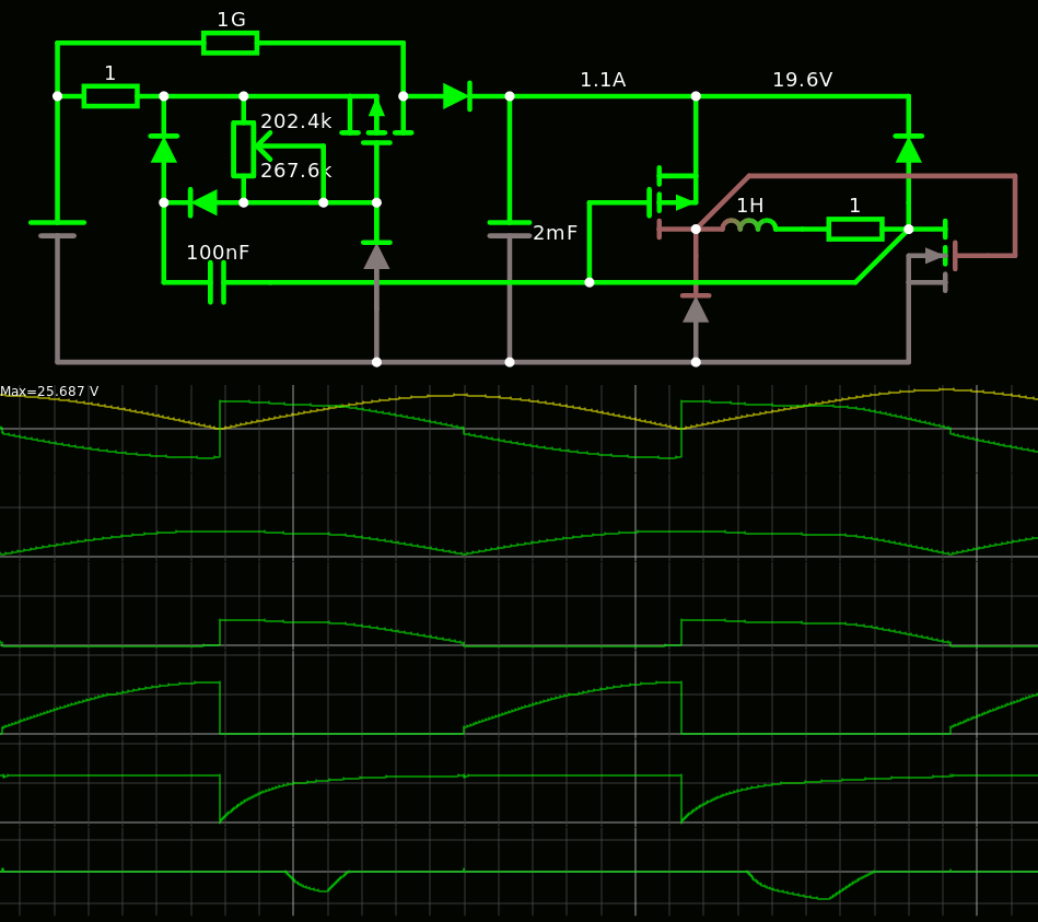
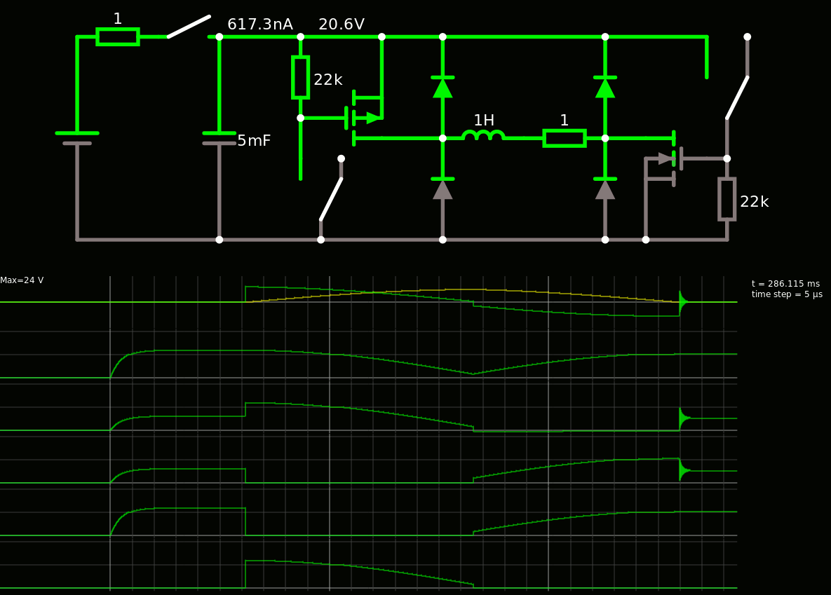
    By trickling some current during the cycle, the total energy increases and the peak reaches 27V for a 24V PSU. It's like a swing, the point is to kick at the right moment to go with the move, but just enough to compensate for the losses.
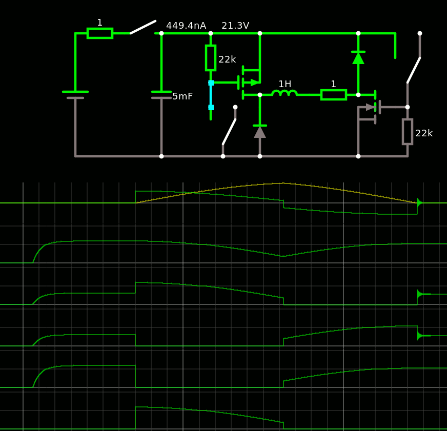
  • Fewer diodes

    Yann Guidon / YGDES05/05/2021 at 02:21 0 comments

    Of course, two diodes were useless.

    The interactive sim

    The removed diodes might help protect the MOSFETs but the opposite diodes take that role, indirectly.

    One cycle loses 3V, or 1/8 of the energy only. This reduces the heating of the coil and the time to recharge the capacitor. Energy savings are not the point, it was more to increase the pulse repeat rate while keeping dissipation low.

    It doesn't matter if the MOSFET do not react immediately, as long it's shorter than 1ms. I have not used "MOSFET Driver" circuits here, adding capacitors  will help simulate the effect of having a laaaaarge gate.

    One big concern is to avoid the saturation of the core. This should be sensed when the current doesn't increase anymore. However the point of this system is to size the capacitor so the voltage decreases before reaching the limits of the coil.

    I wonder if a L298-type bridge could work.

    No, there would be too many power supply issues unless the cycle is shortened before the tank is empty.

    And I aim at 10A currents.

  • First sims

    Yann Guidon / YGDES05/05/2021 at 02:03 0 comments

    After playing with pen&paper, here I am looking at the more detailed behaviour and I got one first system that operates in 3 phases :

    1. load the tank capacitor
    2. when done, discharge the capacitor into the inductor by enabling the N and P MOSFETs
    3. when the capacitor is discharged, recover the energy by blocking the MOSFETs

    The fact that the MOSFET are driven by the capacitor's value provides an avalanche effect because the lower the capacitor discharges, the lower the conductance of the MOSFET so the higher the reactance from the coil.

    Here is the link to the sim if you want to play at home.

    For now, the inductor is arbitrarily chosen to 1H and the tank has 4700µF. Circuitjs helps choose the tank capacitor's value. Here I can expect easily 4 to 5Hz. The period would depend on other parameters that could be controlled by a microcontroller or more analog parts... Some feedback is required though but I don't intend to make a pure analog Finite State Machine.