 Peter Buchegger
The iGate has the following components:
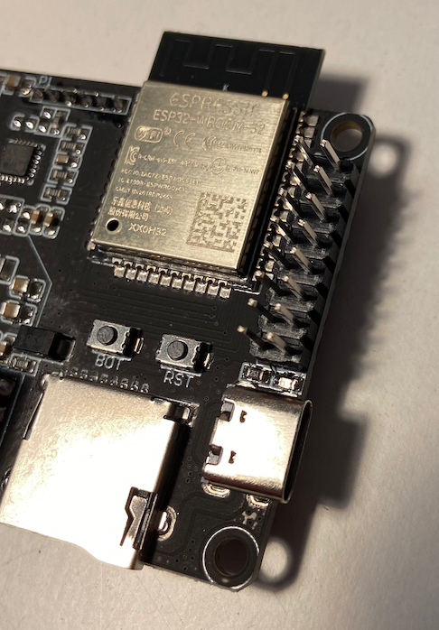
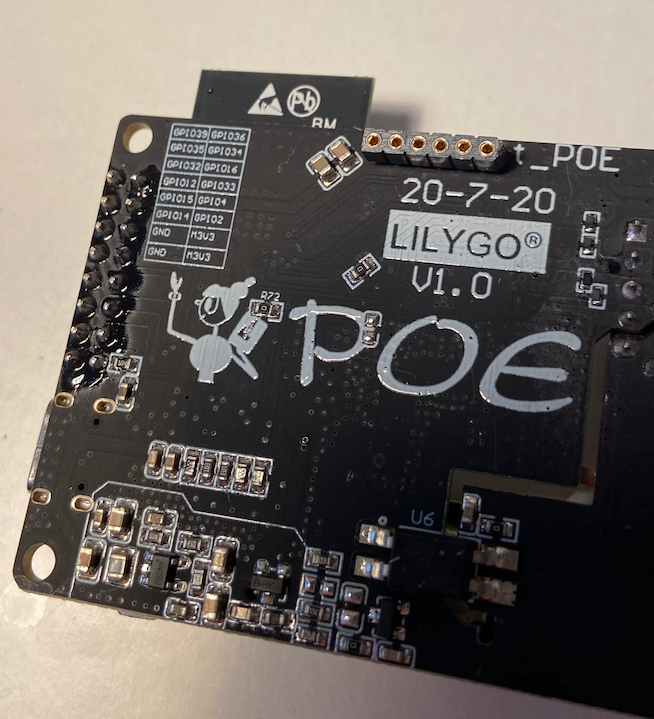
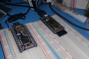
- TTGO T-Internet-PoE board and the
- additional LoRa board which will be mounted to the pinheader of the PoE board.
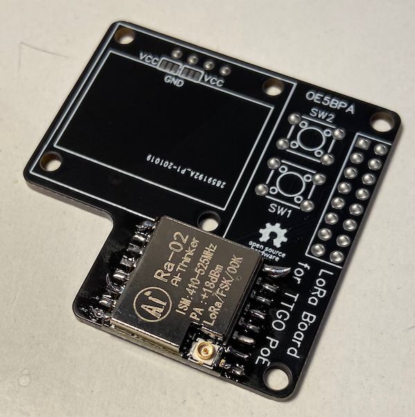
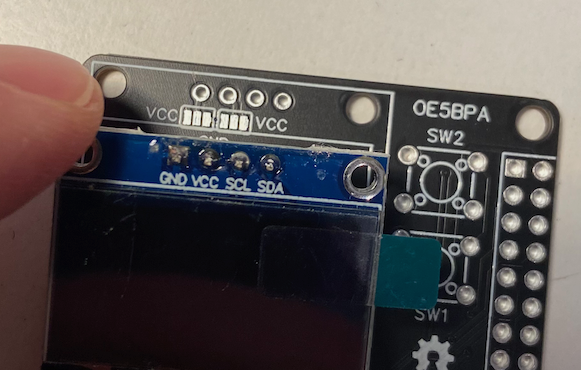
The additional LoRa board has the following components:
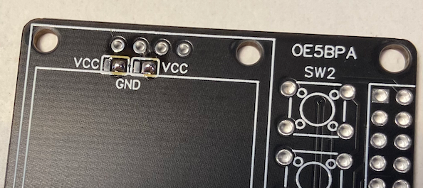
- LoRa Modem (Ra-02)
- OLED 0.96''
- 2 buttons
The board is very simple to solder, so it is a perfect starter kit.
Currently there is just support for an APRS iGate. But there is no limit for additional firmware implementations.
The complete project (hardware and firmware) are open source.
If you want to build our own iGate, you can buy some components from tindie (will be published in the next days).


 Pal-Kristian Engstad
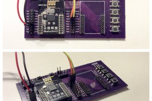
 Lukasz
can You add more keys (for T9 dictionary input type) like as old cell phone
and meybe add a 18650 emergency power (and)or solar panel.
Very nice idea but this is mobile device? I can buy it and use without any assemble?
Is possible put fuzix on this device?