0%
0%
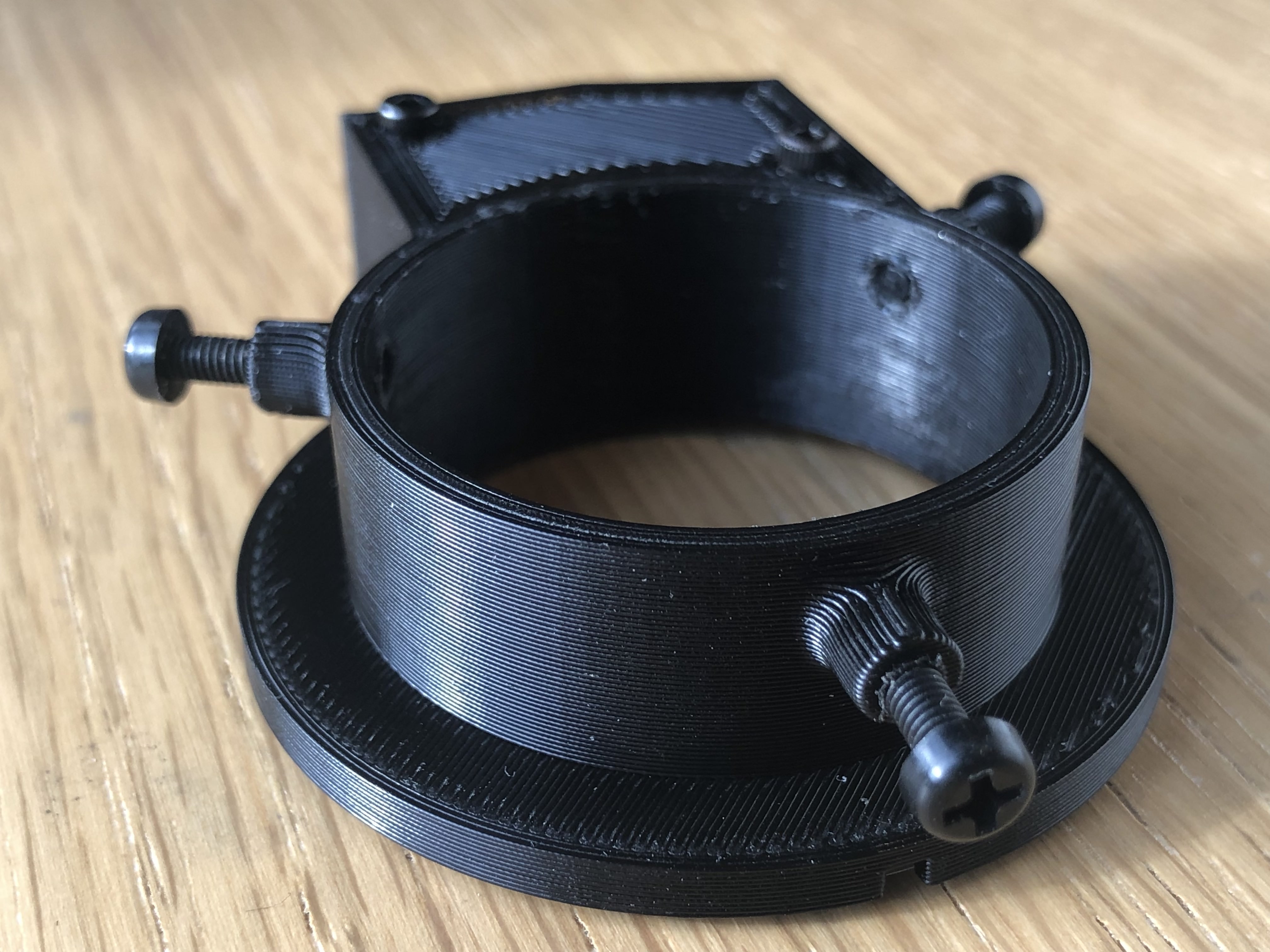
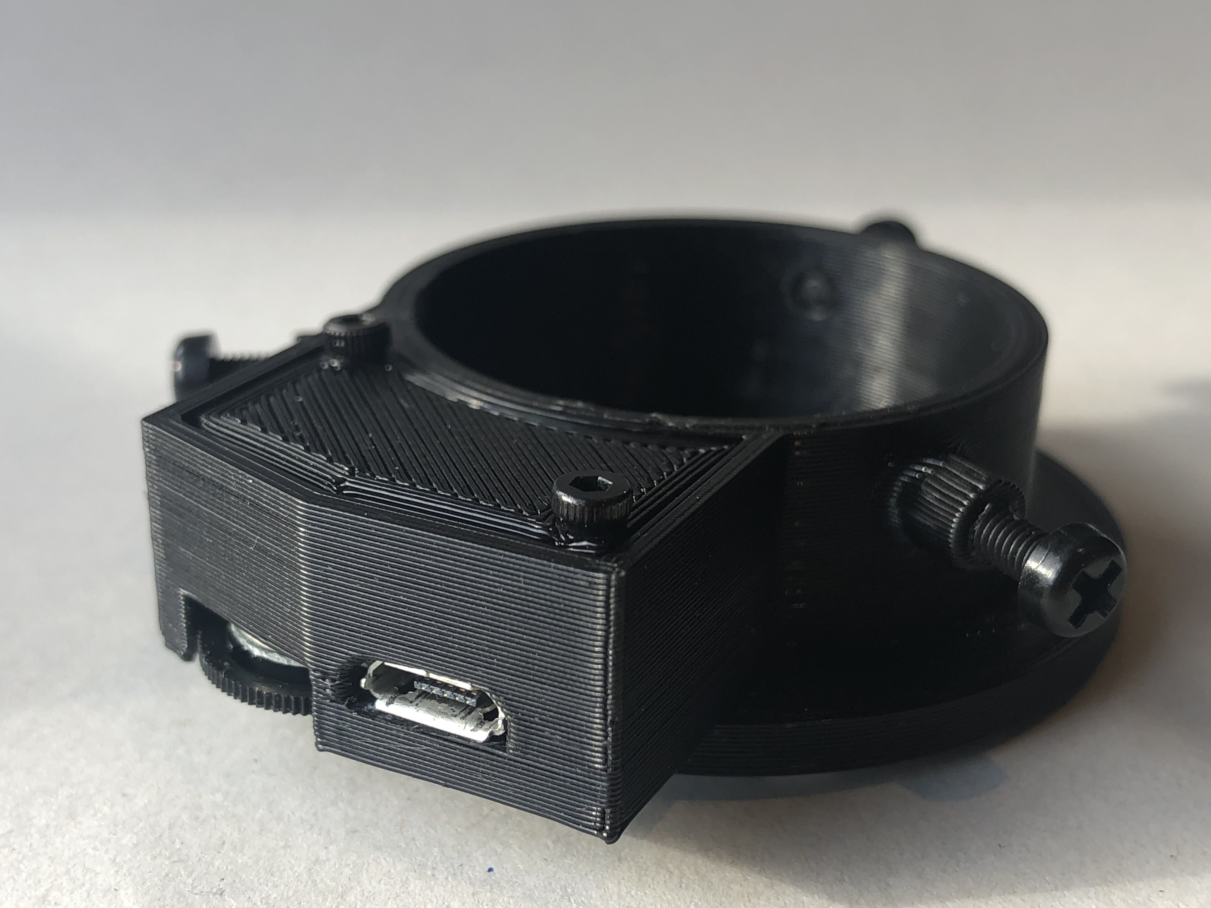
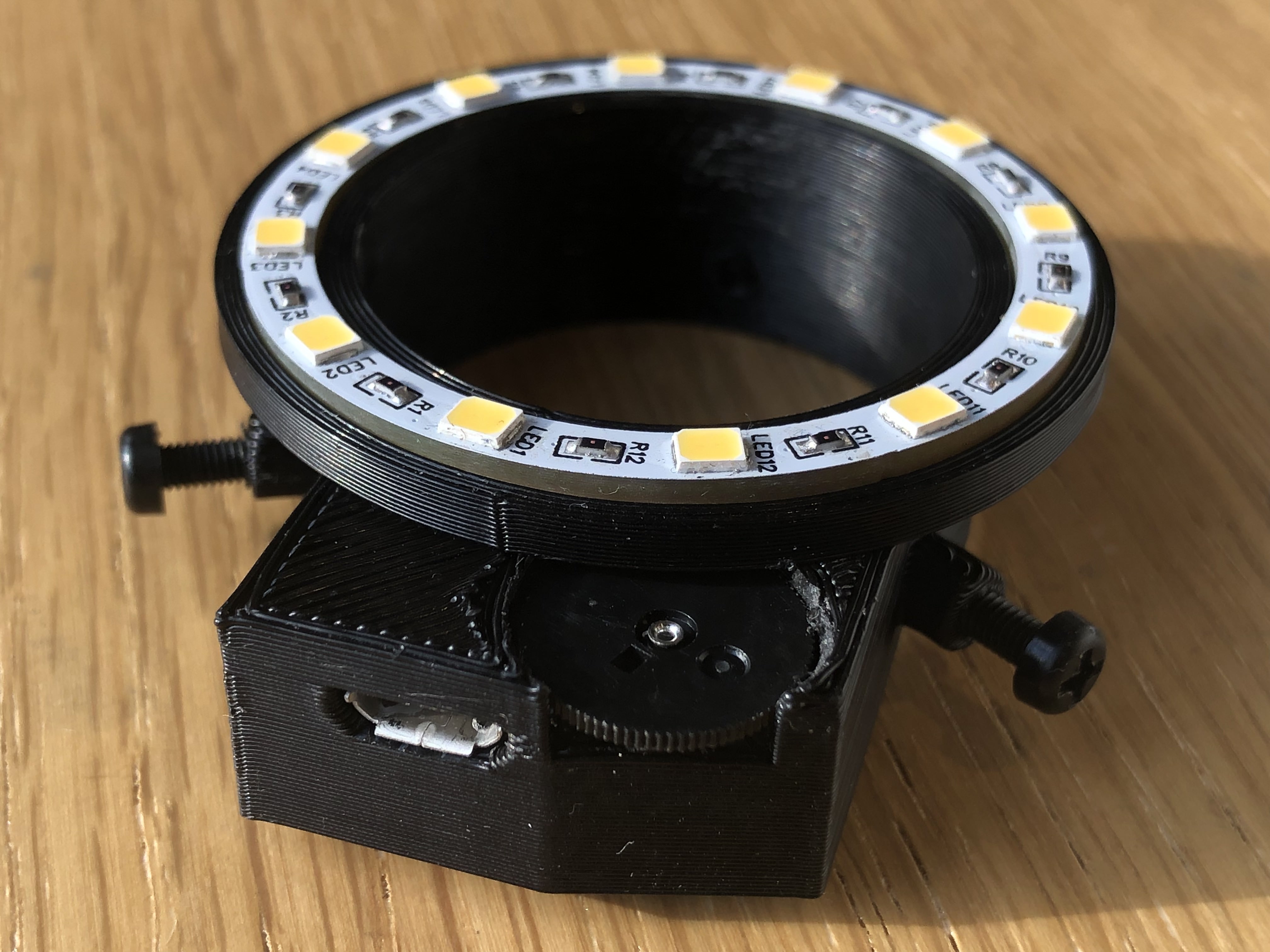
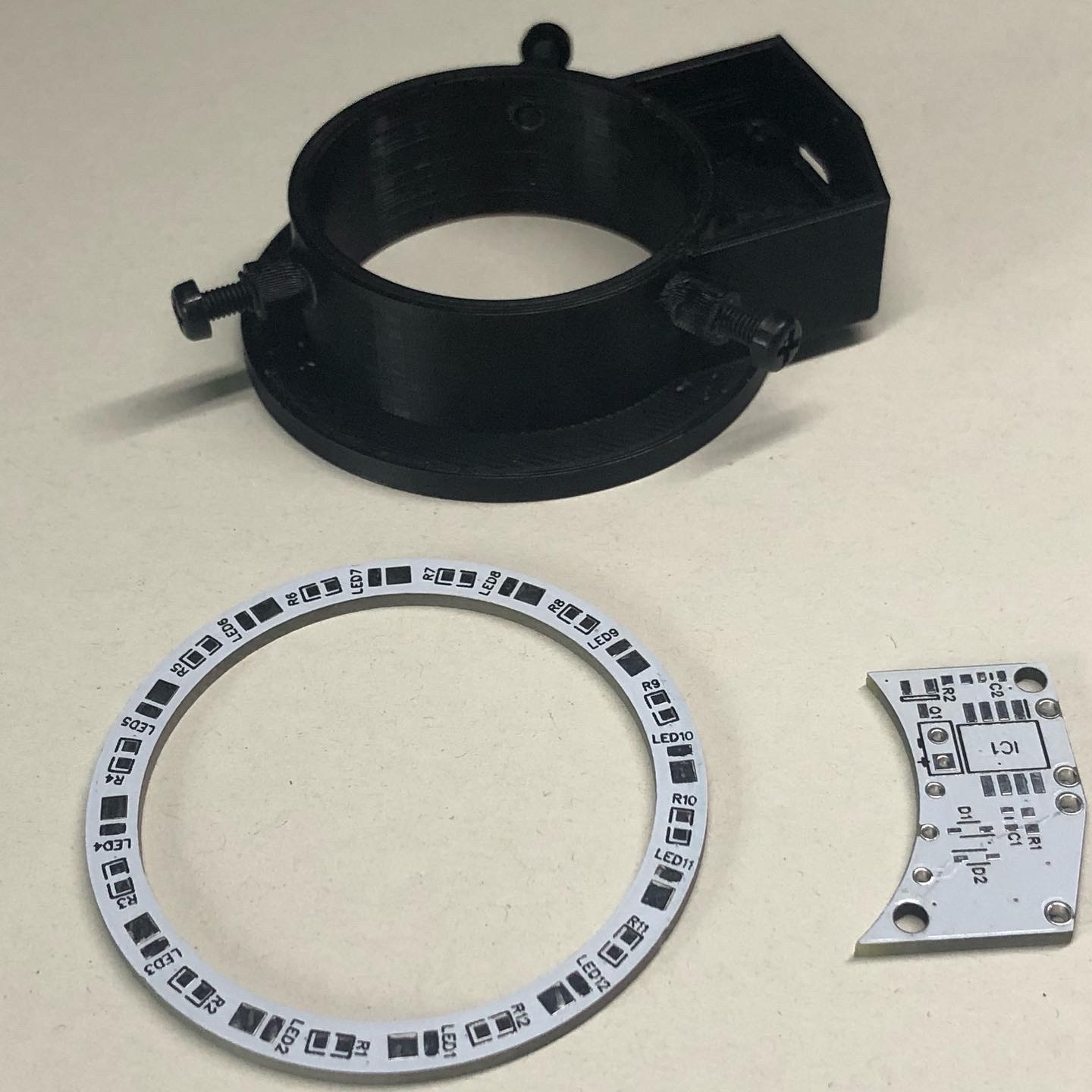
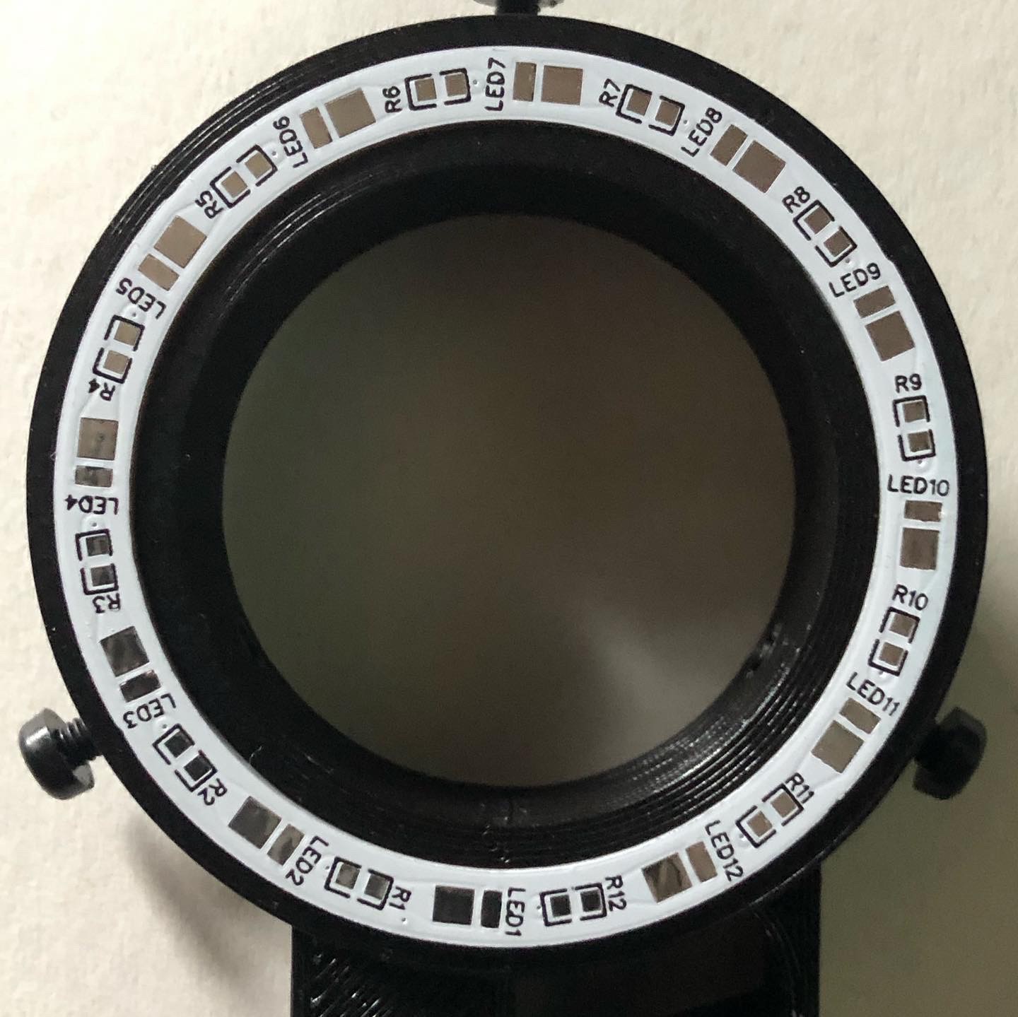
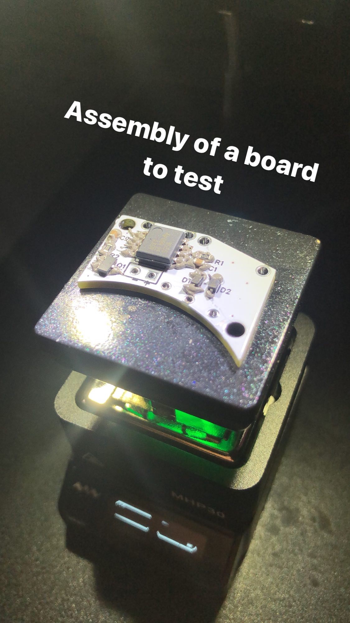
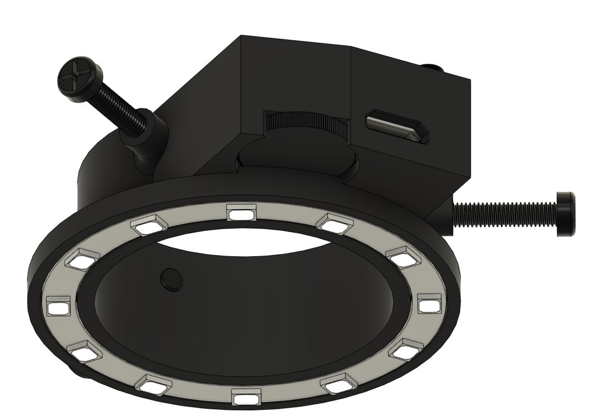
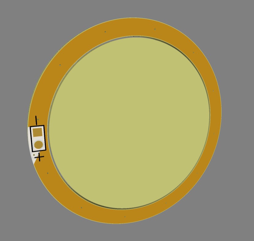
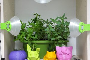
DIY Ringlight
The spotlights on my microscope didn't cut it. So I'm making a ring light to improve video quality.
Become a Hackaday.io member
Already have an account? Log in.
Just one more thing
To make the experience fit your profile, pick a username and tell us what interests you.
Pick an awesome username
hackaday.io/
Your profile's URL: hackaday.io/username. Max 25 alphanumeric characters.
Pick a few interests
Projects that share your interests
People that share your interests


 Arkadi
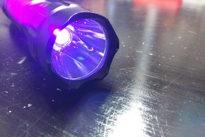
 Pure Engineering
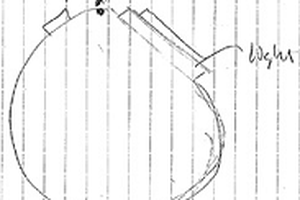
 parkolay
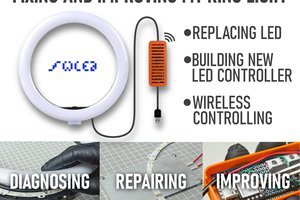
 gokux
gokux
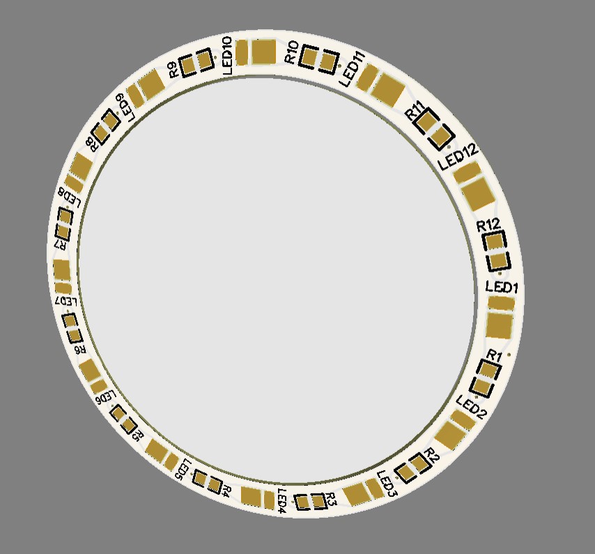
I am wondering, is there an optic lenses suitable for SMD LEDs. To form a more straight light stream.