 brandon
I finally received my opamps and got to work right away building a circuit on a breadboard.
As expected it output 0-10v scaled to match the brightness I told alexa to set it to.
I unboxed one of my lights and hooked it up, but to my surprise I could not dim it under about 75%.
After checking, apparently 0-10v dimmer lights have internal pullup resistors to hold the signal input high when no dimmer is hooked up. This allows them to run at full brightness if they are not controlled. This created a problem because the opamp I was using can barely sink any current at lower output.
I posted to reddit /r/AskElectronics looking for advice and got some good suggestions including adding a transistor on the output of the opamp so that I could sink more current. I tried this but it was way to sensitive. I don't have the knowledge of electrical design to understand why or how I would fix this.
I found that adding a 680 ohm pulldown on the output was enough to overcome the lights pullup. Unfortunately this only worked with a single light. Once another was added in parallel it was not enough. I considered adding a pot to adjust the value of this on the controller board, but decided against it because it would be really hard to get similar performance off each channel. If you had a channel with one light on it and another with three, a 50% brightness setting would be vastly different on them.
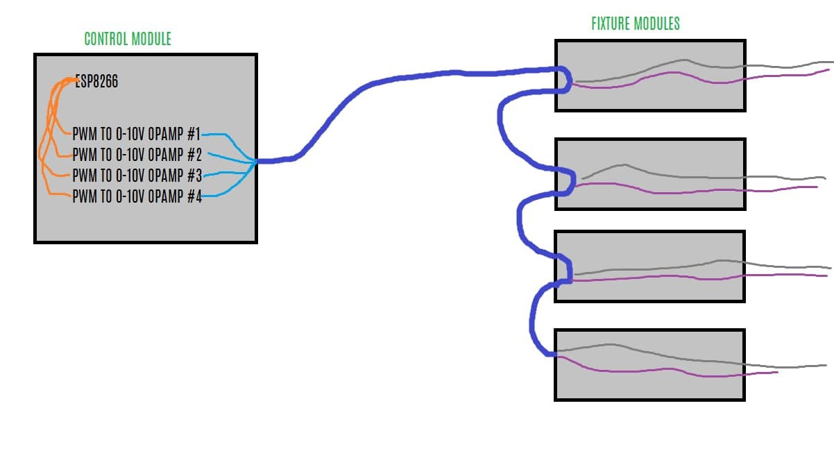
At this point I decided to move the opamps to the light modules instead of the controller module. Initially my plan was to have the system be modular like this:
No active circuitry would be in the light modules. The new plan was to have it laid out like this:
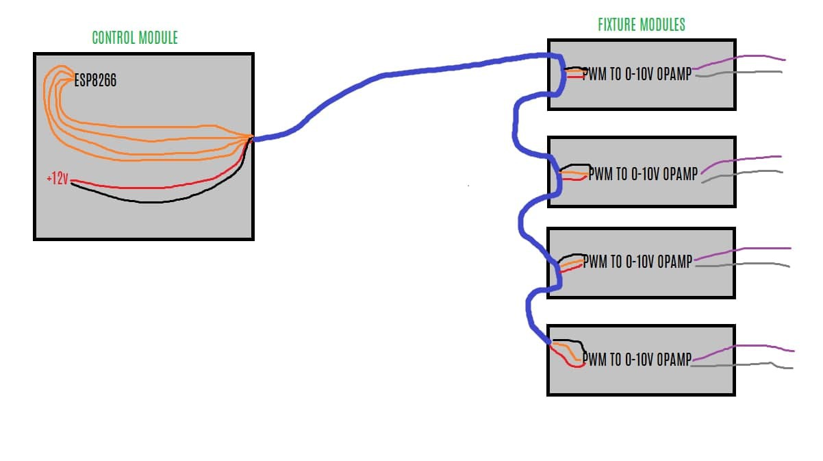
The control module would only contain the ESP and power supplies and all the DAC would happen at the light.
I made a couple of test boards out of some proto board and tested to see how they behaved when the pwm signal was sent over a hundred feet of ethernet cable. The good news is they behaved just fine. The bad news is that I ran into a problem where having multiple opamps on the same 12v supply would cause the output voltage to dip if multiple opamps were on. This is not going to work because I do not want other lights to dim when others are turned on.
To test just how bad this problem was I built a breadboard with 5 opamps:
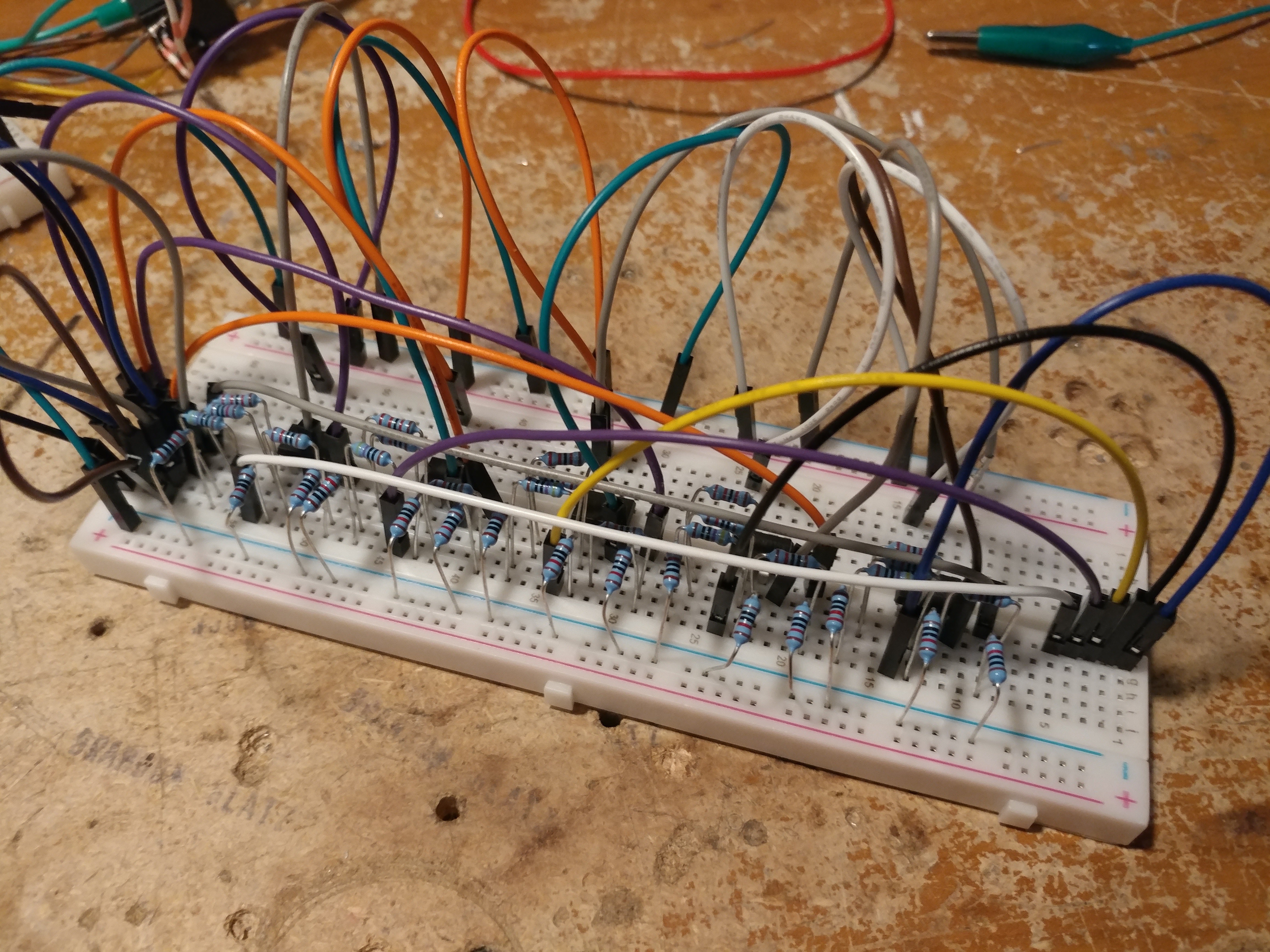
Turns out it was pretty bad. Since the opamps were each on their own board now, I decided it would be easiest to just add a buck converter on each light module to supply the opamp with 12v. This also allowed me to run 24v along the ethernet cables used for daisy chaining which helps cut down on losses as the opamps need a steady 12v supply in order to put out the right voltage signal.
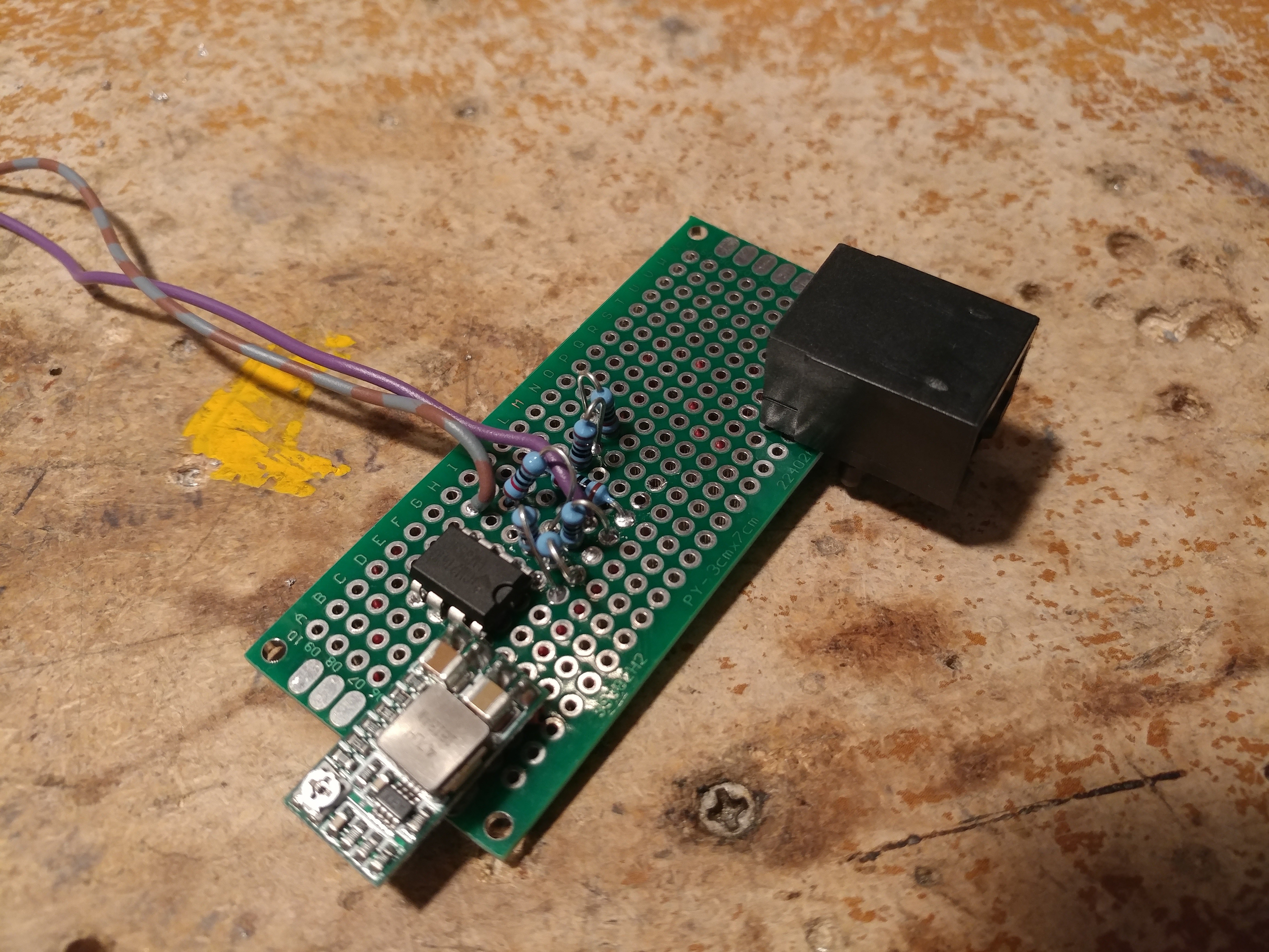
After testing on a breadboard, I added them onto my proto board and tested them using 24v fed over a few ethernet cables. With a multimeter hooked up to each of my two test boards I was able to control the voltage being put out via alexa and had similar performance off of each one without one being able to affect the other. I would have made more test boards but I only had 3 of the buck converters.
I also managed to kill some opamps in a really dumb way: When reworking one of these test boards I forgot to hook up the ground from the buck converter. this allowed 24v to pass straight through and fried the chips. Lesson learned.
The second test board looks similar to this, but with a dual RJ45 port:
Discussions
Become a Hackaday.io Member
Create an account to leave a comment. Already have an account? Log In.