 Evan Li
I rarely work at my electronic workbench, even though it's complete with displays, power supplies, oscilloscopes, and soldering stations. I prefer to work on firmware and testing on my main desktop. Having a handy source of power, other than the 5 volts that USB provides, is very handy. I didn't want to spend too much time building something complicated and decided to go with parts I could get off Amazon.
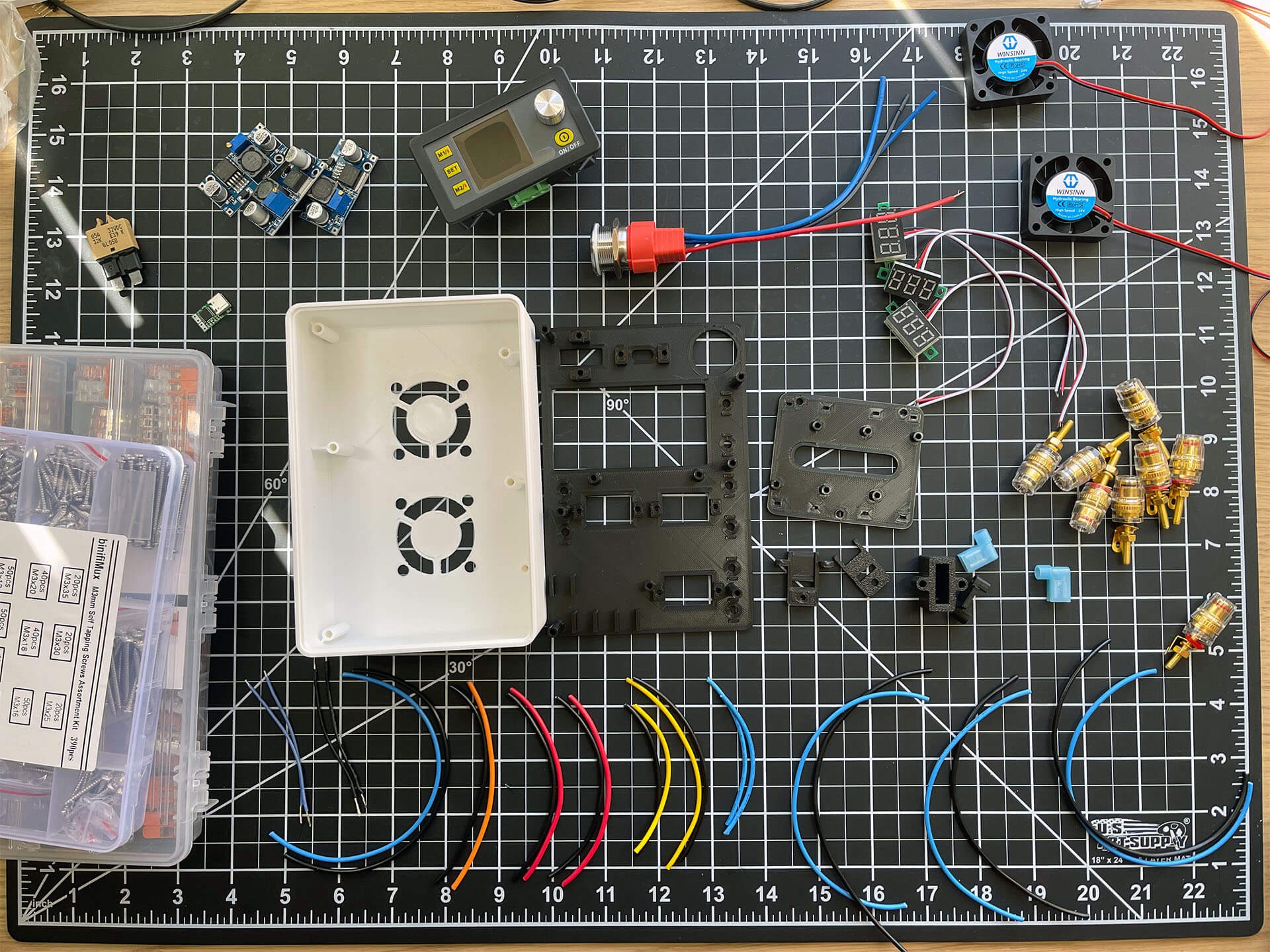
The casing and other 3d printed parts took about a day to model and tweak, but are pretty basic. All the other parts are available via Amazon
- USB-C PD 20V Trigger Module [Amazon]
- DSP5005 Variable Power Supply [Amazon]
- LM2596 DC/DC Voltage Regulator [Amazon]
- LED Digital Voltmeter Gauge [Amazon]
- Banana Plug Socket Connector [Amazon]
- Latching Push Button Switch [Amazon]
- Manual Reset Low Profile ATC Circuit Breakers [Amazon]
- 40mm 24V Fans [Amazon]
- 18 AWG 6 Colors [Amazon]
- 18 AWG Orange Wire [Amazon]
- Quick Splice Terminals Connectors [Amazon]
- WAGO 221 Lever-Nuts [Amazon]
- M4 Self Tapping Countersunk Screws [Amazon]
- M3 Self Tapping Phillips Pan Head Screws [Amazon]

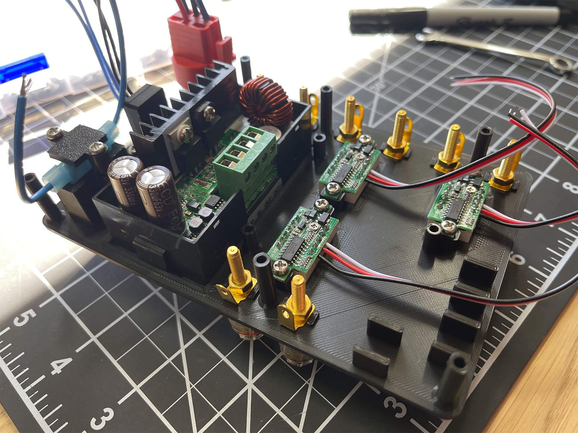
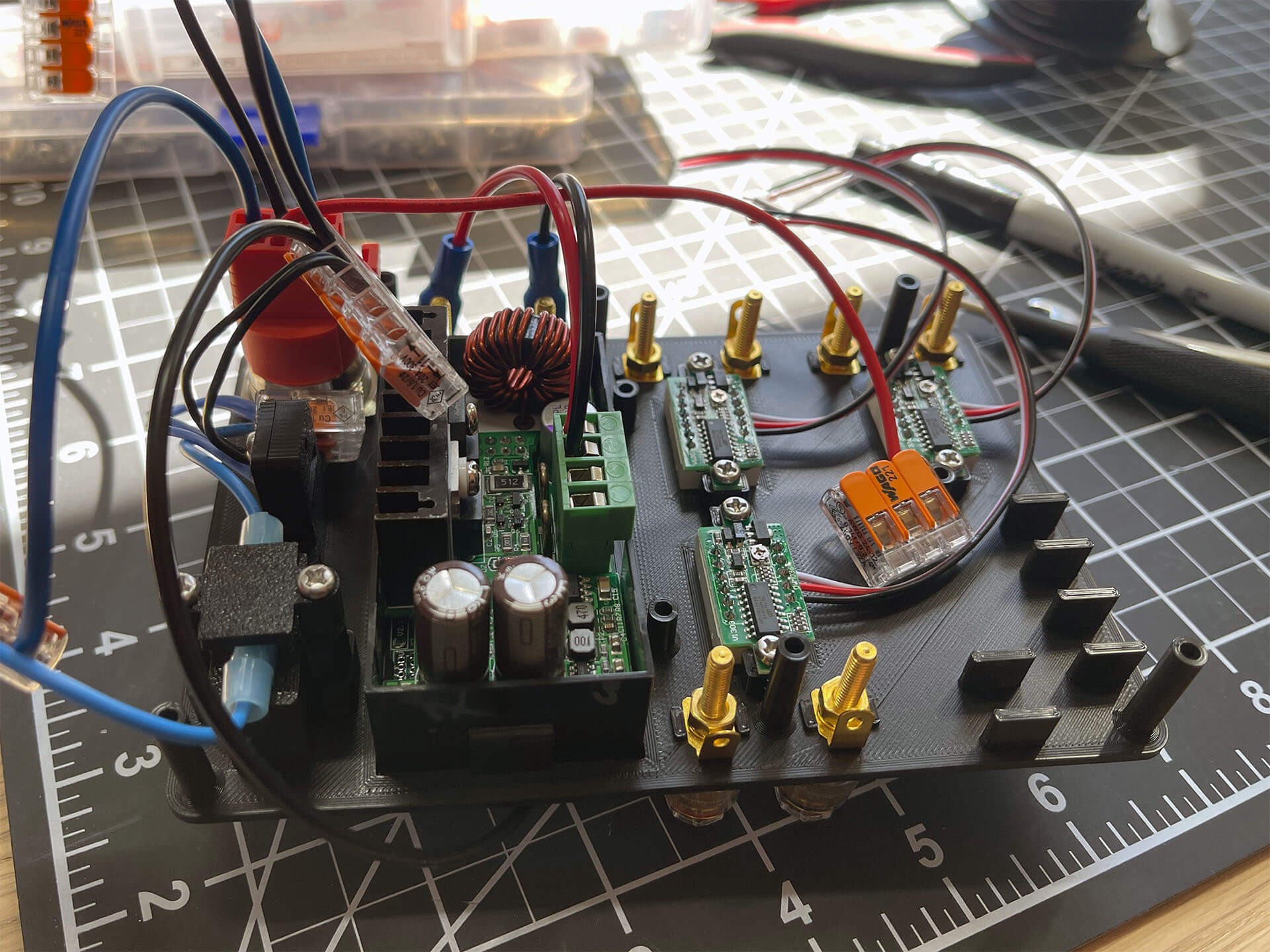
The USB PD module would provide 20V at up to 5A to power the whole thing. The 24V fans are hooked up directly to the 20V source so that the fans will run when power is connected just to make sure things stay cool inside. The 5A circuit breaker provides some safety incase of a short. The latching switch allows the voltage regulators to be turned on and off. I'm exceeding the rating of the switch, but for this application it shouldn't be too much of an issue. The LED indicator and the voltmeters are powered by the 12V output from one of the LM2596 regulators.
The DSP5005 and LM2596 regulator are all powered by 20V. For the DSP5005, this limits the maximum output voltage to around 18V. The individual LM2596 modules are adjusted to output 3.3V, 5V, and 12V. The final outputs for each regulator are connected to a banana plug connector.
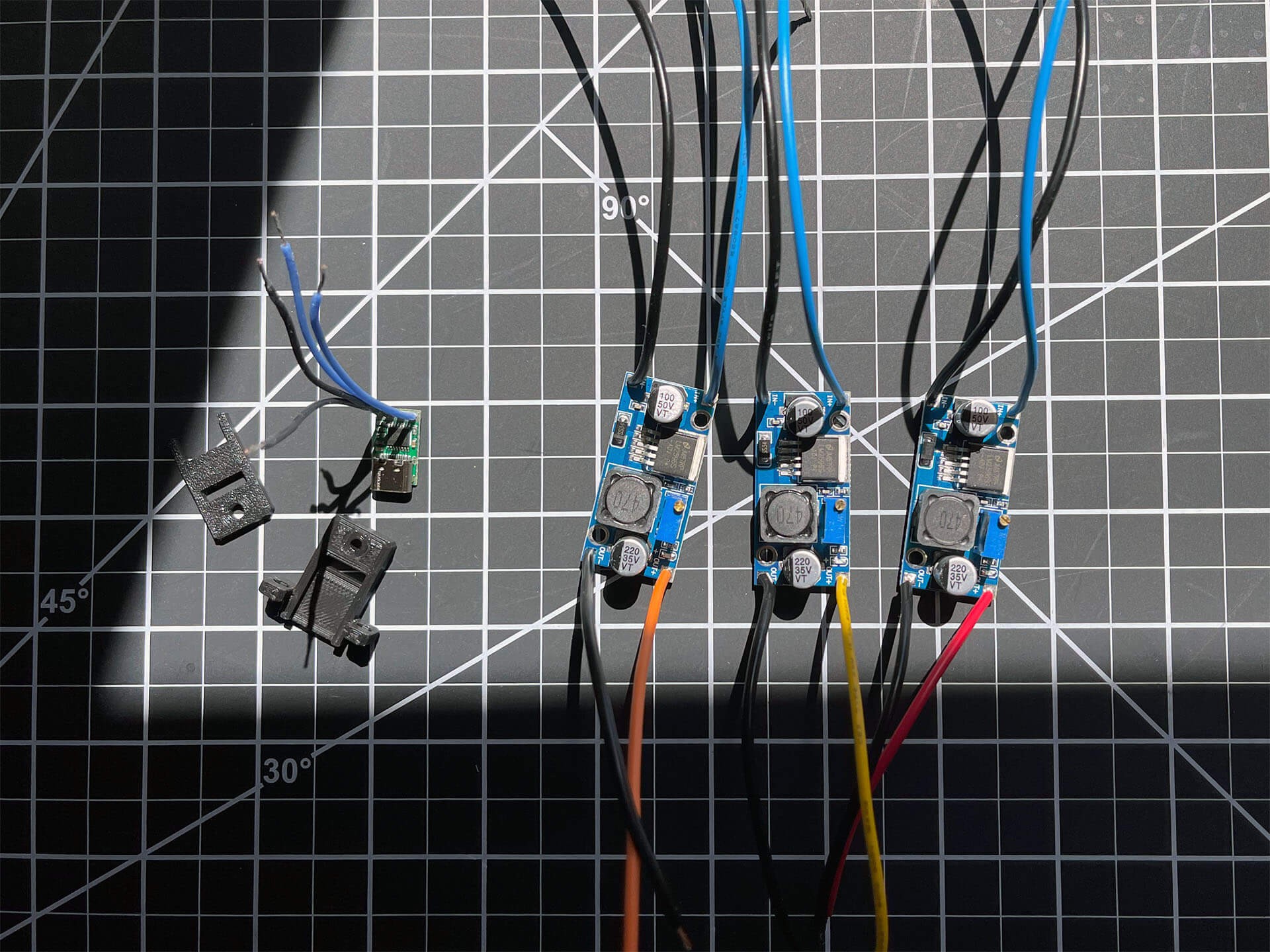
The maximum input current is limited to 5A by the USB PD standard, so 18 AWG wire is more than sufficient. The only soldering required for this project is to attach the output on the USB PD module and the input/outputs on the LM2596 modules.

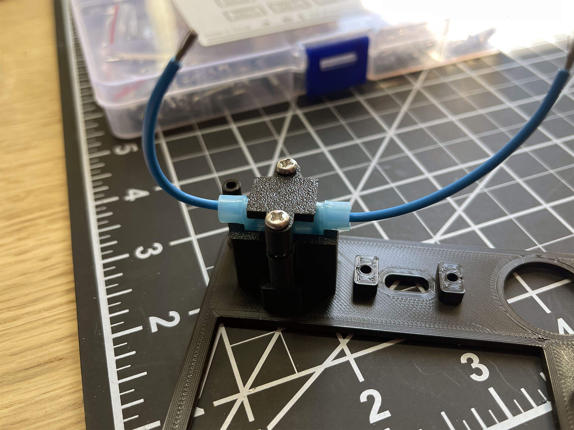
Mounting the USB PD module is a pain. As the module has no mounting holes, the 3D printing mount uses the edges of the PCB for alignment and clamping force to keep it in place. A single M3x6mm pan head screw is used to keep the two halves together.
The ATC circuit breaker holder is just a couple of right angle quick connectors held together. Two M3x12mm pan head screws are used to keep the connectors in place.
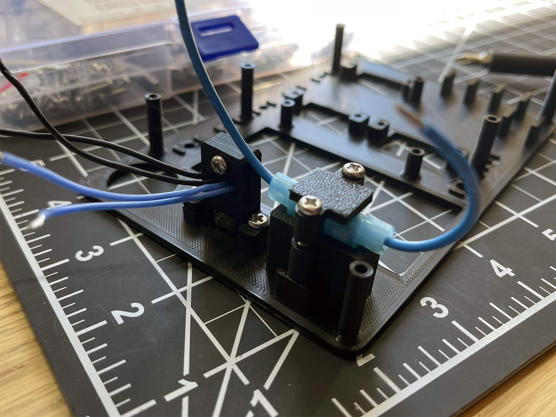
Two more M3x6mm pan head screws secure the USB PD module mount to the faceplate.
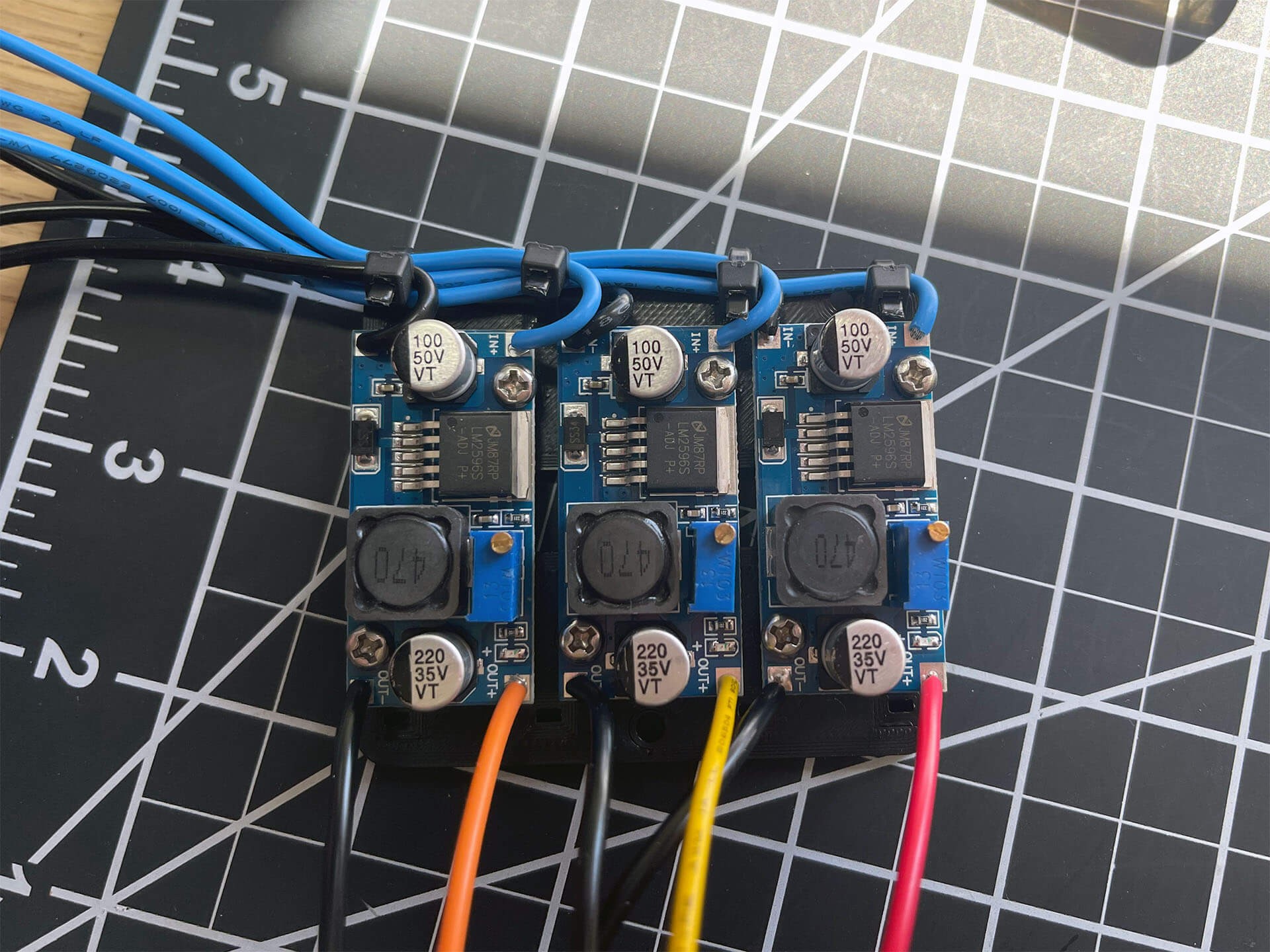
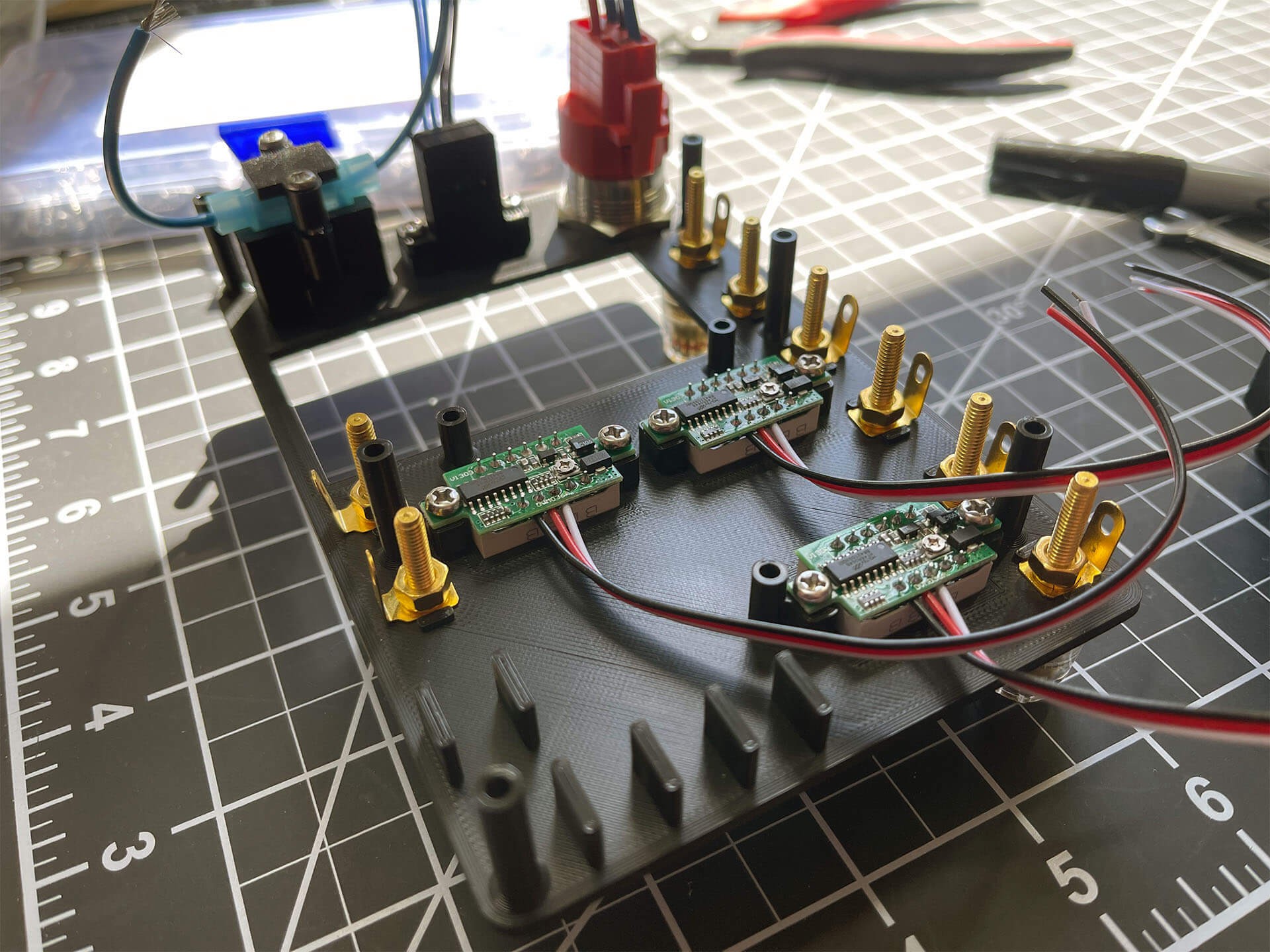
The three LM2596 are mounted to the regulator tray with six M3x6mm pan head screws. The tray has some hole designed for cable ties to keep the input wires organized.

The three voltmeters are secured to the face plate with six M3x6mm pan head screws.
Extra wires were removed the latching switches harness, as space was going to tight inside the case. The switch is mounted with the hardware that was included. The banana plugs are screwed in place with the connector spade orientation retained by features on the face plate.
The DSP5005 pushes into the opening on the face plate and should snap in to place.
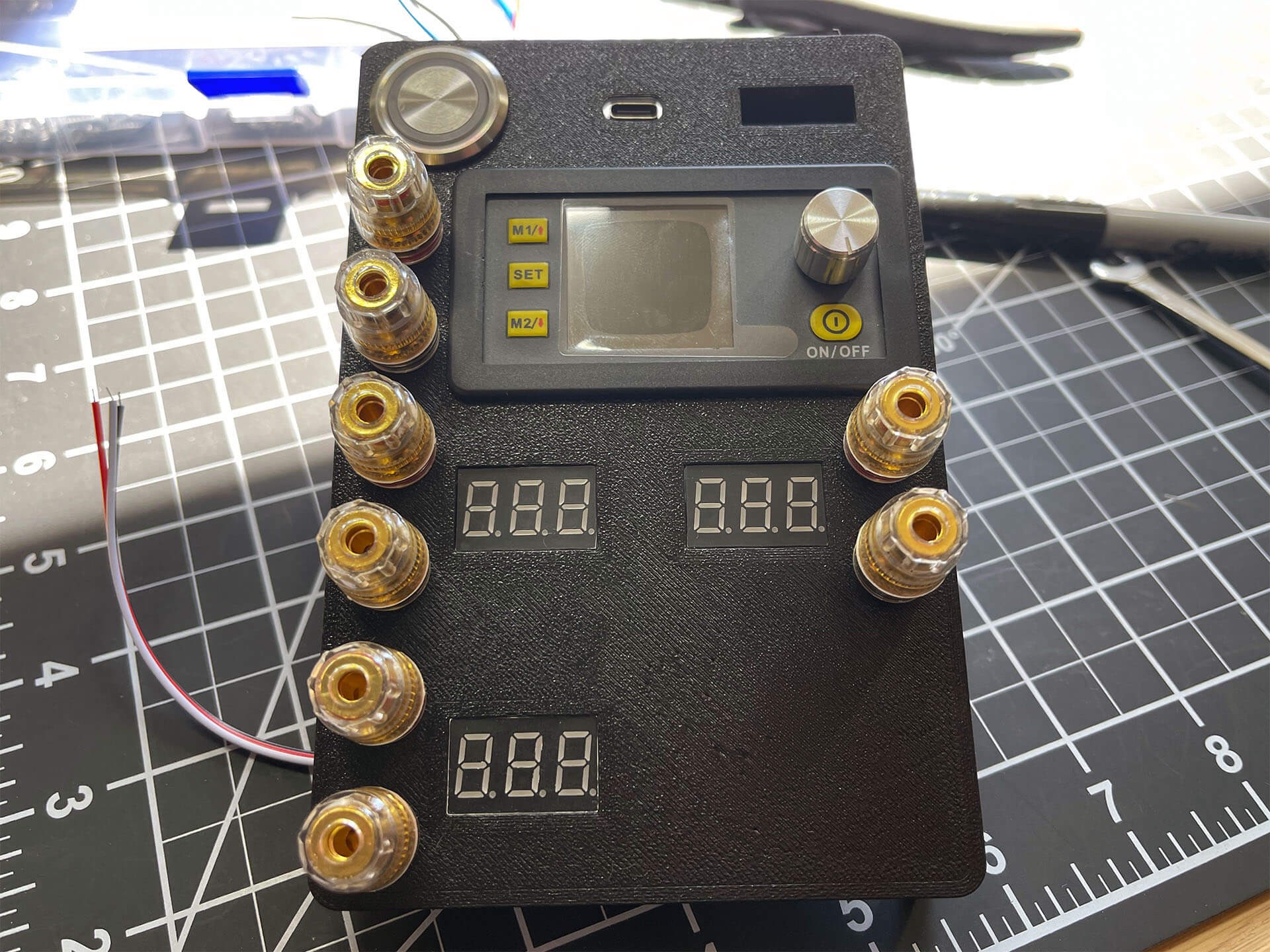
The banana plug connector are paired with the corresponding voltmeter. Output is above and ground is below. The ATC circuit breaker fits perfectly in the open slot.
To keep the project quick and easy to troubleshoot, I went with lever-nuts instead of soldered or crimped connections. The lever-nuts are larger but some features on the face plate keeps things organized.
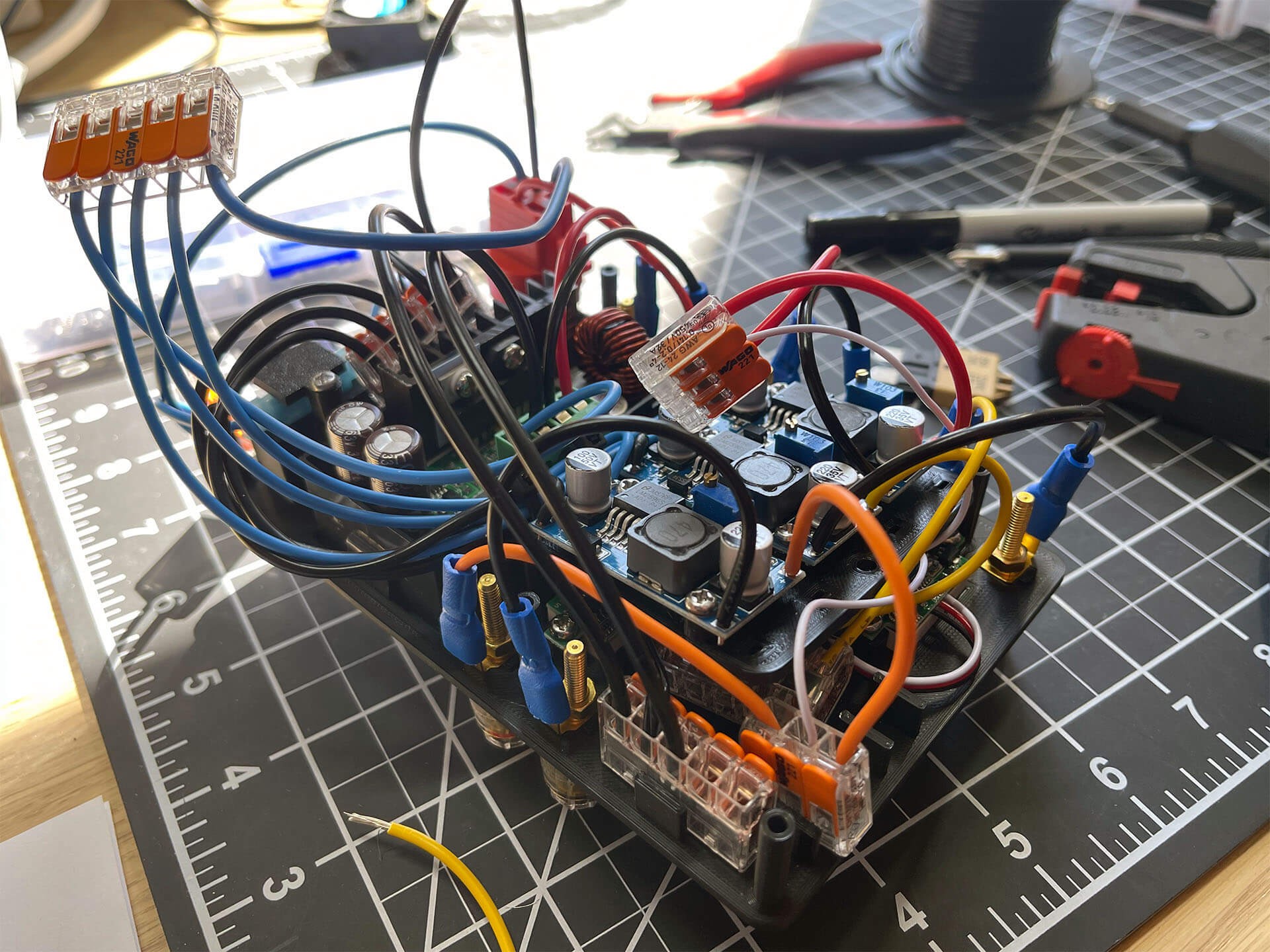
The regulator tray is mounted to the face plate after all the wire lengths were checked and adjusted. I ended up only using two M3x6mm pan head screws with the mounting holes on the regulator tray. The input cables on the regulator tray made putting screws there too difficult. With...
Read more »
 tobychui
 darth_llamah
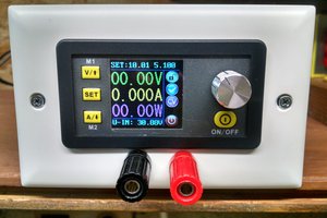
 ogdento
 Macrofarad
Very nice. I knew it was going to be good as soon as I saw those fans!