 UltraReidar
Making a power meter for my bicycle, because the once in store is too expensive for the components and technology behind it.
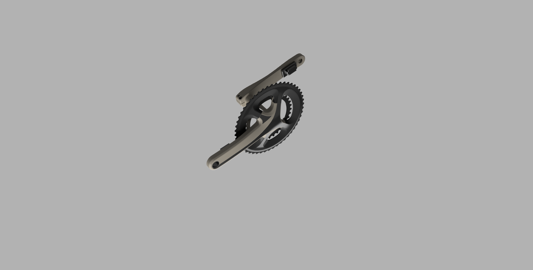
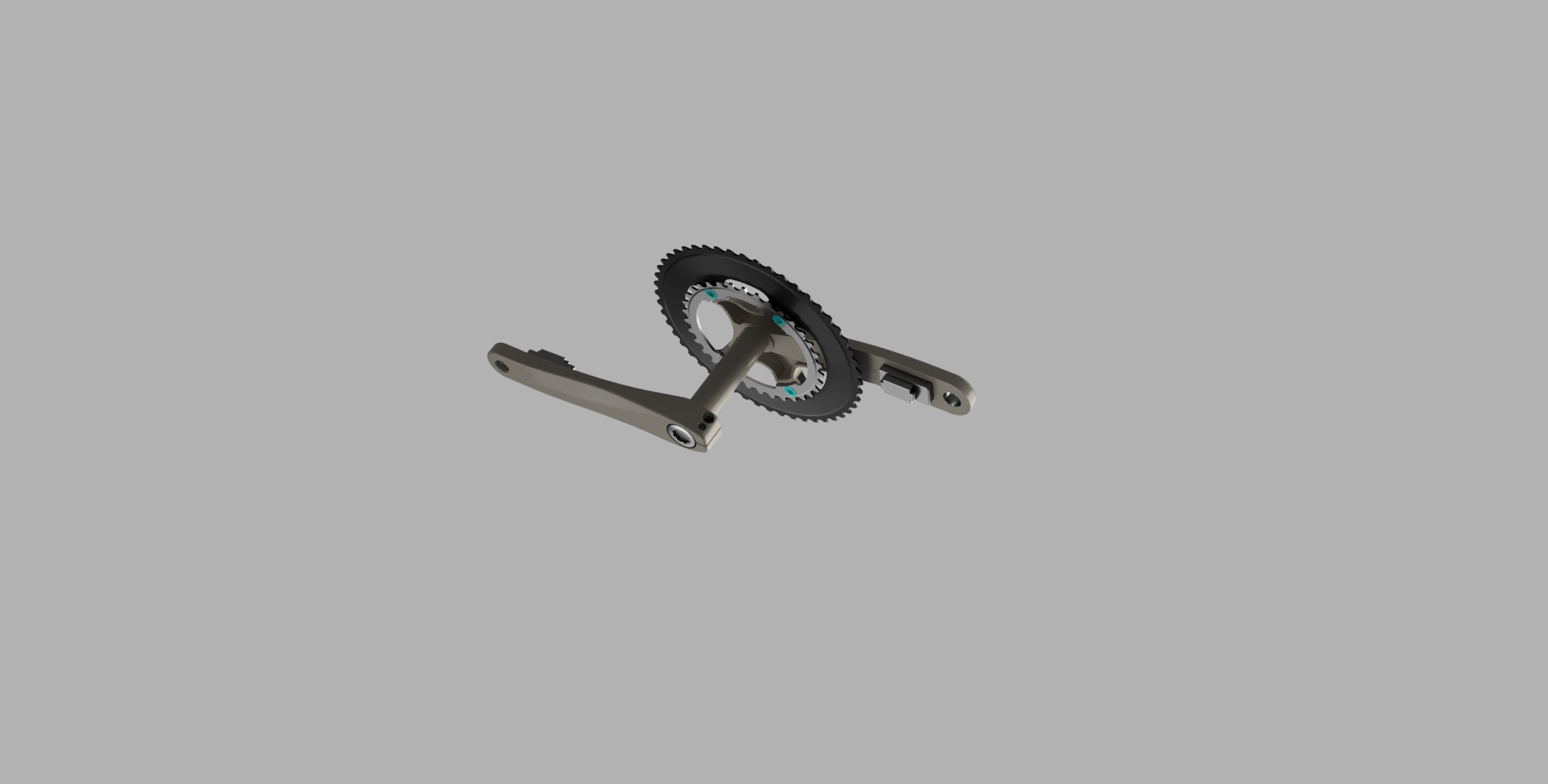
Two different version, one for mounting on the inside of the crank and one to mount on the crank arm.
Send me a message if I should proceed with the crank arm mounted version or inside the crank.
Battery side needs to be solder by hand, while the other side comes pre-soldered.
Going to use a NRF52810 for sending over ANT to my Garmin Forerunner 245.
When I have finished the project, I will give out all my documentation. If you follow me on Github I will post some code and files along the way, but I won’t use a lot of time publishing before completed and success.
If you want a PCB card, send me a message and we can find a fair price.


 tomcircuit
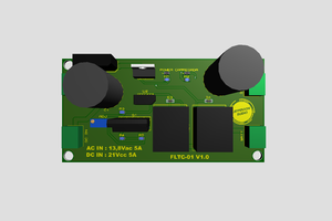
 Jefferson Bueno
 CYUL
CYUL
First and foremost this is just for fun and learning new things. If this ends up working and with an accuracy of 10%, no problem. As long as it is showing more wattage than reality, compensating for some weak legs.
Joking aside, I appreciate your comment.
For the amplifier, it is just a blunder not adding one, but it could be easily sorted by adding it as a separate module for now. I'm working for my university this summer so I would probably find some cool amplifiers there. I will probably find some good adhesive there as well, but if it lasts a month, it lasts a month.
I haven't put much thought into the project yet, so the asymmetric cranks haven't struck me. Watced your video about it, and it does makes a lot of sense. Im using the 6800 crank myself, so could be worse I guess ;). Going to try to sort it as good as possible, but i could still put the strain gauge inside the crank like TeamZwatt, thoughts? The length of the wire would probably become an issue here. As you mention in your video, the software was for simulating the strain gauge was free, i would probably try this out to find the best position. I do have a pretty accurate CAD model of my crank so.
I thought of having a third strain gauge between the two existing, but that would probably have little flex. But if you have two sets of two strain gauge one set of the upper section and one on the lower section of the crank. Then I belive it is possible to simplefie the measurements so we can linarize it. Or simulate a lot of spots on the crank arm, find a formula for the upper part and one for the lower part and, use that to compensate the measurements. But it is just a thought and it is possible complete garbage.
Yet again, great input, and great youtube channel, a little goldmine for this project.