 Ben Steer
What’s in a lab?
I had to make some decisions as to what tools and components would be crucial to making this thing as useful as possible. There are quite a few tools that are versatile enough to be a part of any laboratory, and there are some great lists out there, such as EEVBlog’s guide to putting together a cheap lab. However, I’ll tailor some of the components specifically for robotics.
Here’s a summary of the key bits and pieces that will go into the lab:
- Powered tools: Soldering station, multimeter, PC-based oscilloscope, variable-voltage power supply, Li-ion battery charger, flexible LED lamp.
- Hand tools: Cutting/crimping tools, tweezers, screwdrivers, calipers, strippers, solder/desolder accessories, safety glasses.
- Components: Resistors, capacitors, LEDs, op amps, transistors, motor controllers, stepper drivers, regulators/bucks, fasteners, perfboards, breadboards, wire, microcontrollers, etc.
This sounds like a recipe for a really good time. But how will we fit all this into a suitcase without making a complete mess?
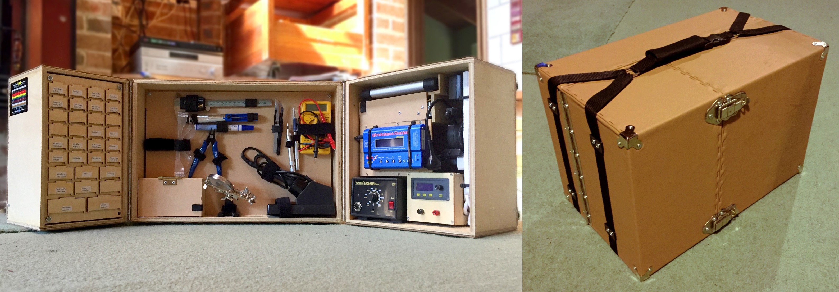
Laboratory layout
Our lab-in-a-box will consist of three main compartments: a chest of drawers for electrical components, a big wall to attach tools with velcro straps, and a shelf with a powerboard for the bigger equipment. The compartments will be hinged together, so they can open out from each other like doors, and will look a little something like this:
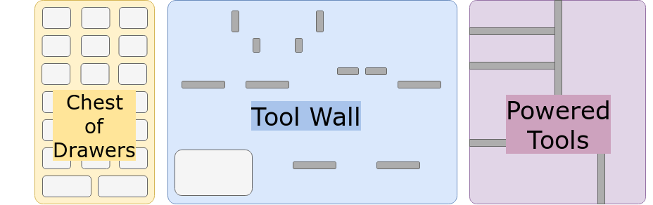
Drawers in the left door, tools in the back, power in the right door. Sounds like a plan.
Building the boxes
After buying all the tools and components, I took some measurements, did some arranging and worked out the best dimensions for the lab boxes in order to keep them small.
In case I ended up buying completely new tools or wanted to rearrange them, I decided to house the tools/components on insertable backboards. These would screw into the back panel of the lab boxes using some threaded inserts (I’ll show you what these look like in a second).
Cutting it up
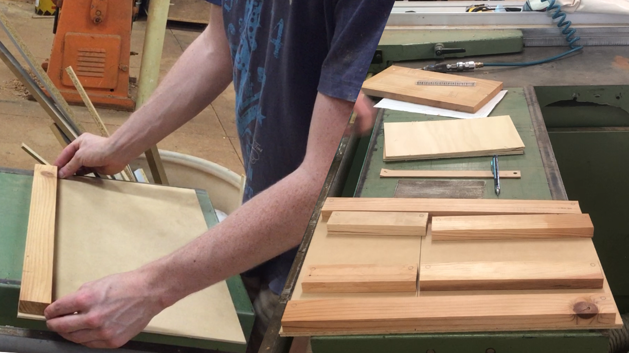
Time to hit the wood shop! The panels comprising the box were cut mostly from plywood, with some solid pine strips on the back panels for additional strength, and to house the threaded inserts. I used a vertical arm saw to make the cuts, which was ideal for the job.
Glue and screw
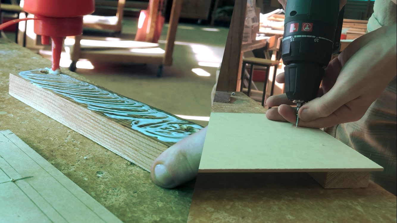
With all the pieces cut, the next step was to predrill, glue and screw our pine strips to our back panels. I used PVA glue and a cordless drill for the job. Sometimes you can avoid needing to clamp your glued pieces for hours if you screw them tightly together!
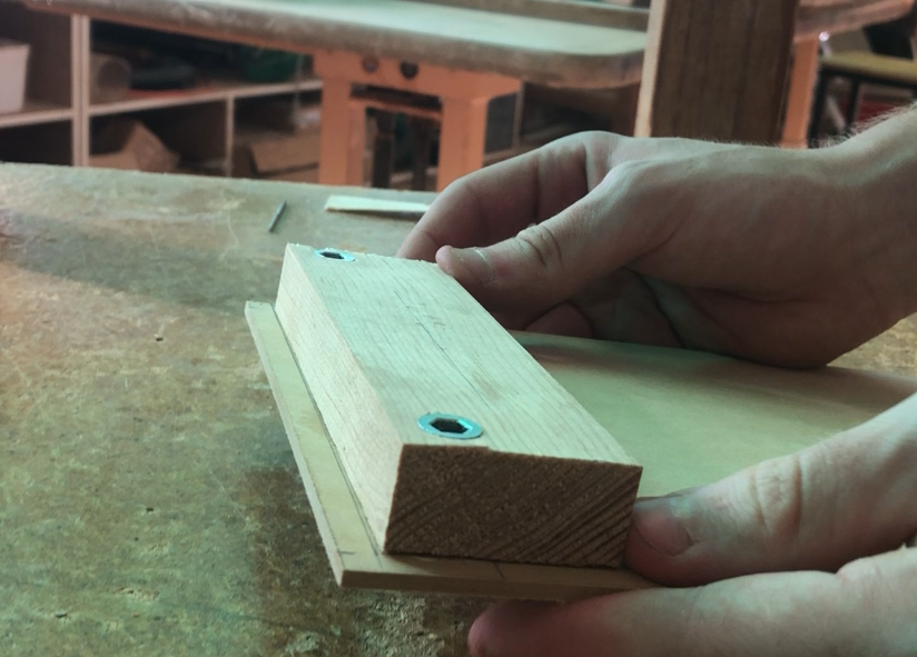
In the picture above, you can see the M6 threaded inserts (sometimes called “screw-in” inserts for timber) in the pine blocks, which I installed before attaching them to the back panel. These simply require a predrilled hole, which you then screw the insert into.
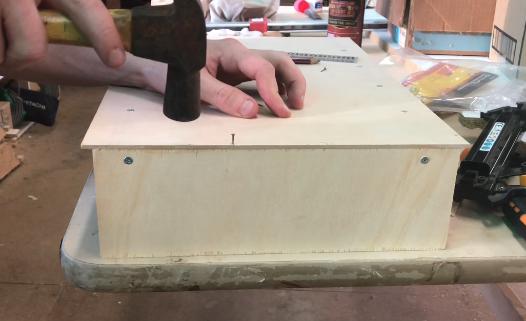
With the backboards finished, I then glued and screwed the side and top panels of each box. These were screwed into the pine blocks from the side, and fastened to the thin back panel with small tack nails.
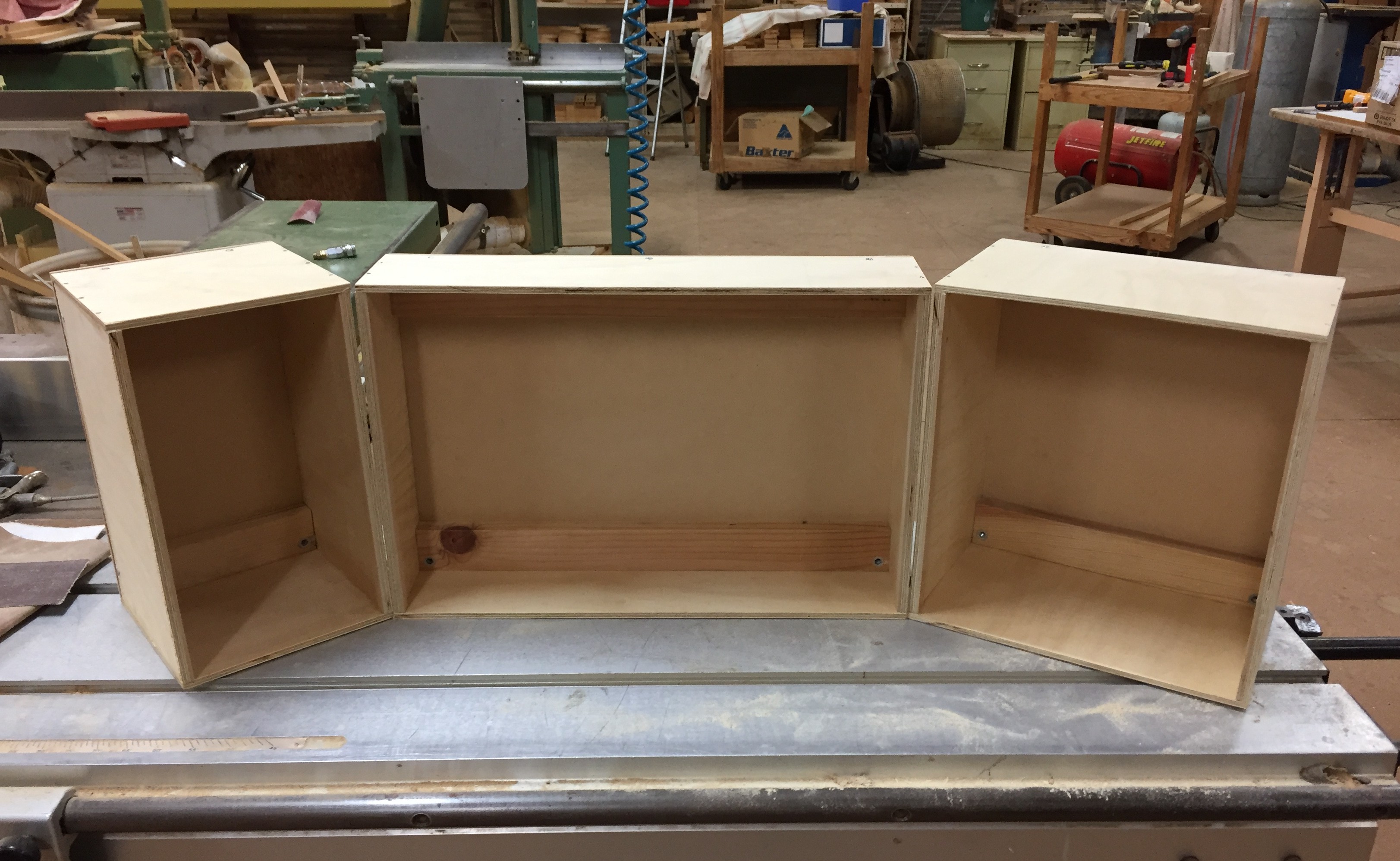
There you have it, three boxes, ready to be turned into one! However, before we get carried away with installing hinges, let’s improve the look.
Focusing on aesthetics
As much as we all like wooden boxes, I think they leave a bit to be desired in the aesthetics department. I decided to give it a vintage look, and upholster it with some brown vinyl (faux leather).
Making patterns
If you’ve ever wrapped a birthday or christmas present, then you’ll be at least a little familiar with what this process involves. I am most definitely an amateur at upholstery, but there’s not much on the line here.
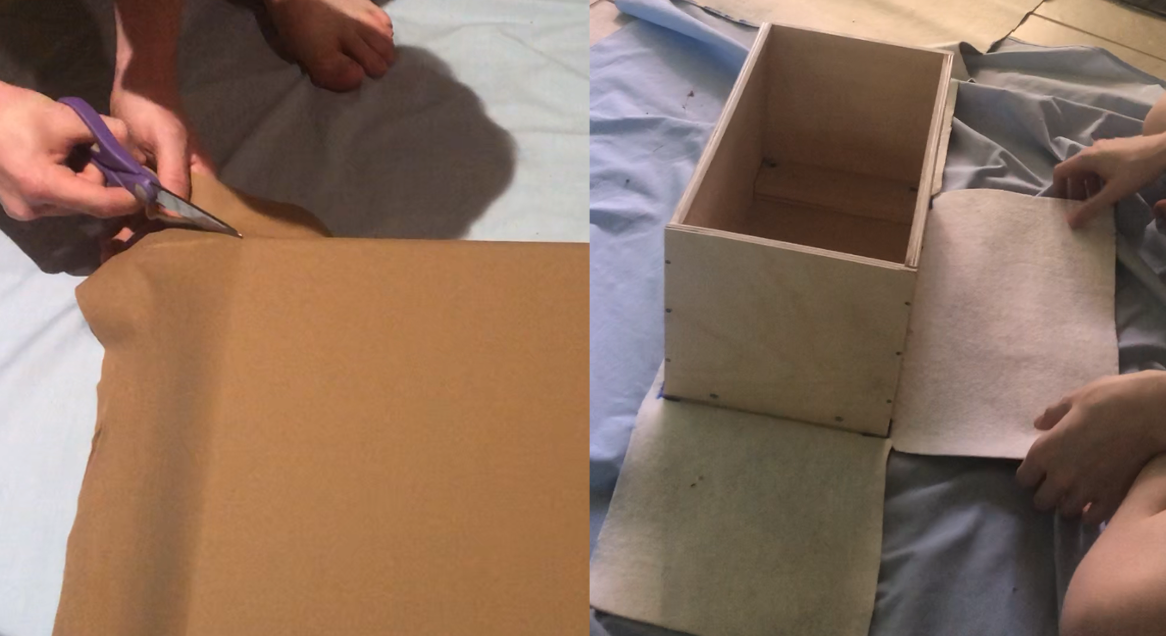
I went ahead and cut out some squares of vinyl, allowing a little excess size around the border so I could fold the edges back over themselves later. Folding the vinyl at the edges tends to look better, and in my case, hides the fluffy, white underside of the material. I also cut squares out of the corners; otherwise the material would bunch up when folding it up onto the panels.
Sticking it to the box
Using PVA glue again, my partner and I coated each side of the box and lay the material flat over it. It was important to remove air gaps between the vinyl and the wood by kneading and pressing them out, to give a smooth, consistent surface.
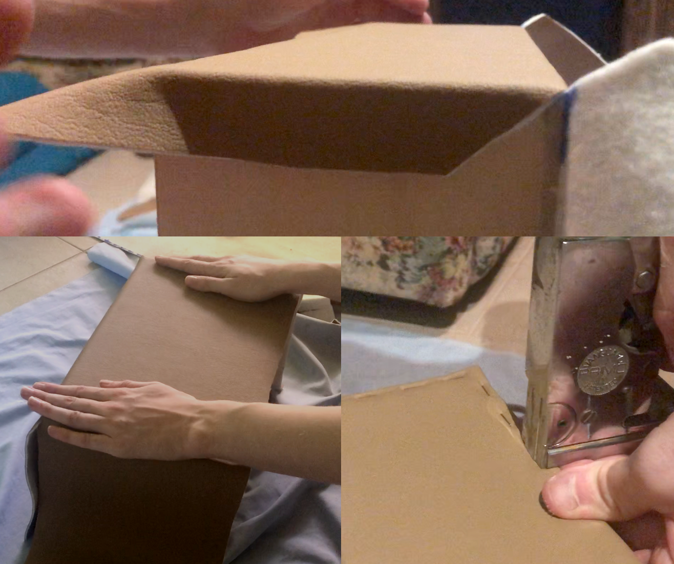
We folded all the edges of the vinyl and stapled them into the wood with bronze-coloured staples, to match the material. I don’t think visible staples are particularly desirable when it comes to upholstery, but I can live with it. The boxes definitely look cooler now!
When three boxes become one
With all the vinyl attached, it’s finally time to connect those beautiful boxes together. Hopefully they’re a nice fit! Once we finish assembling the box, we’ll be able to move on to installing all our goodies. Let’s get to it.
Whingeing for a hingeing
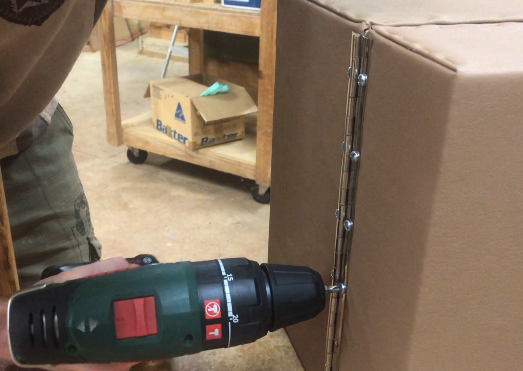
I used stainless steel continuous hinges to connect the doors — one on each side. Luckily, the hinges at Bunnings were the exact height of my box! I simply screwed these into the reinforced side panels of the boxes.
Gasping for a clasping
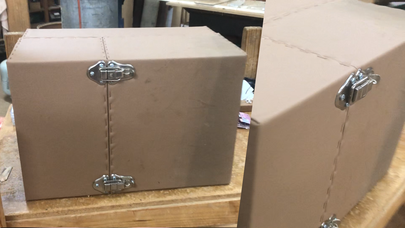
To keep the two side doors shut, I installed two suitcase clasps at the top and bottom of the doors. These screw directly into the pine blocks on the backboard of each door. They also have a little hole for a padlock, so we can keep our electrical goodies safe from villains, who would use them for evil.
Finishing touches
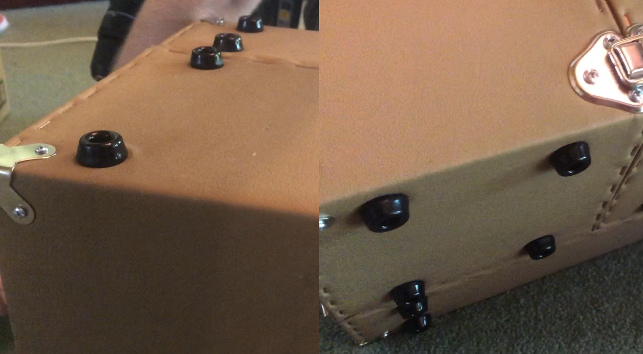
In addition to the hinges and clasps, I screwed some rubber feet into the bottom of the boxes, to avoid scraping the vinyl and staples across whatever surface the lab sits on. I also added some metal suitcase corners, for that extra bit of class.
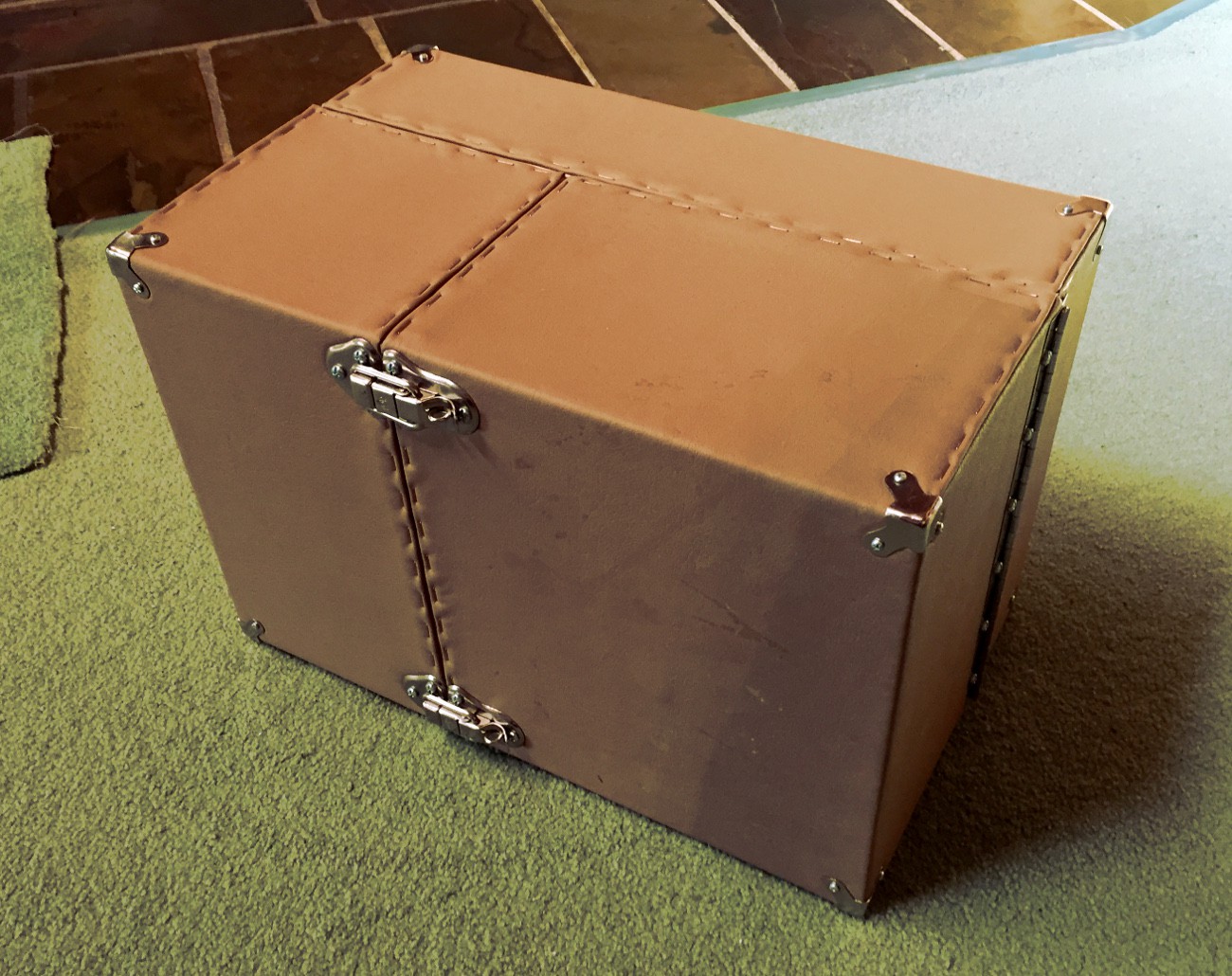
That’s our laboratory box finished! I think it turned out pretty well. However, it’s no good if we don’t have anywhere to put our stuff.
Chest of drawers for electrical components
As I mentioned earlier, we’re going to keep our components inside insertable housings, which will screw into the backboards of our boxes. For the leftmost door, this will look like a chest of drawers, which will house all our electrical components and doodads.
To save myself from meticulously cutting out a billion tiny pieces for a chest of drawers, I decided to CAD the drawers and have them laser cut from 3mm ply. Several different drawer sizes are included in the design, so we can fit larger things like perfboards and development boards.
CAD design
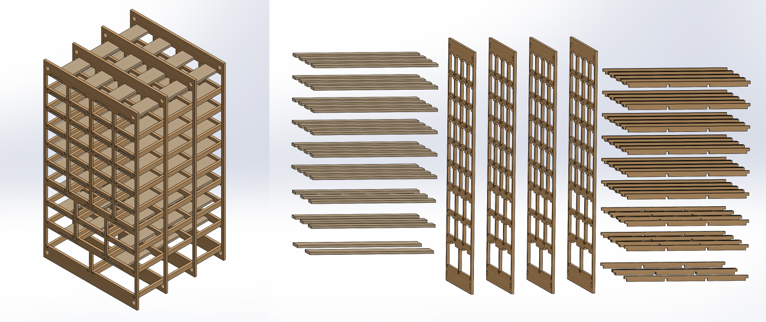
The design consists of four wooden panels, connected together via a number of slotted inserts. These will be glued together during assembly. There are also a number of flat bars to be glued inside the ceiling of each drawer compartment, to flatten out the components inside the drawers and keep them from getting caught on the frame. The chest will fasten to the laboratory backboard using M6 threaded rods through the corners.
Laser cutting and assembling
I had my designs laser cut by Vector & Raster Laser Services in Wallan, and they turned out very nicely.
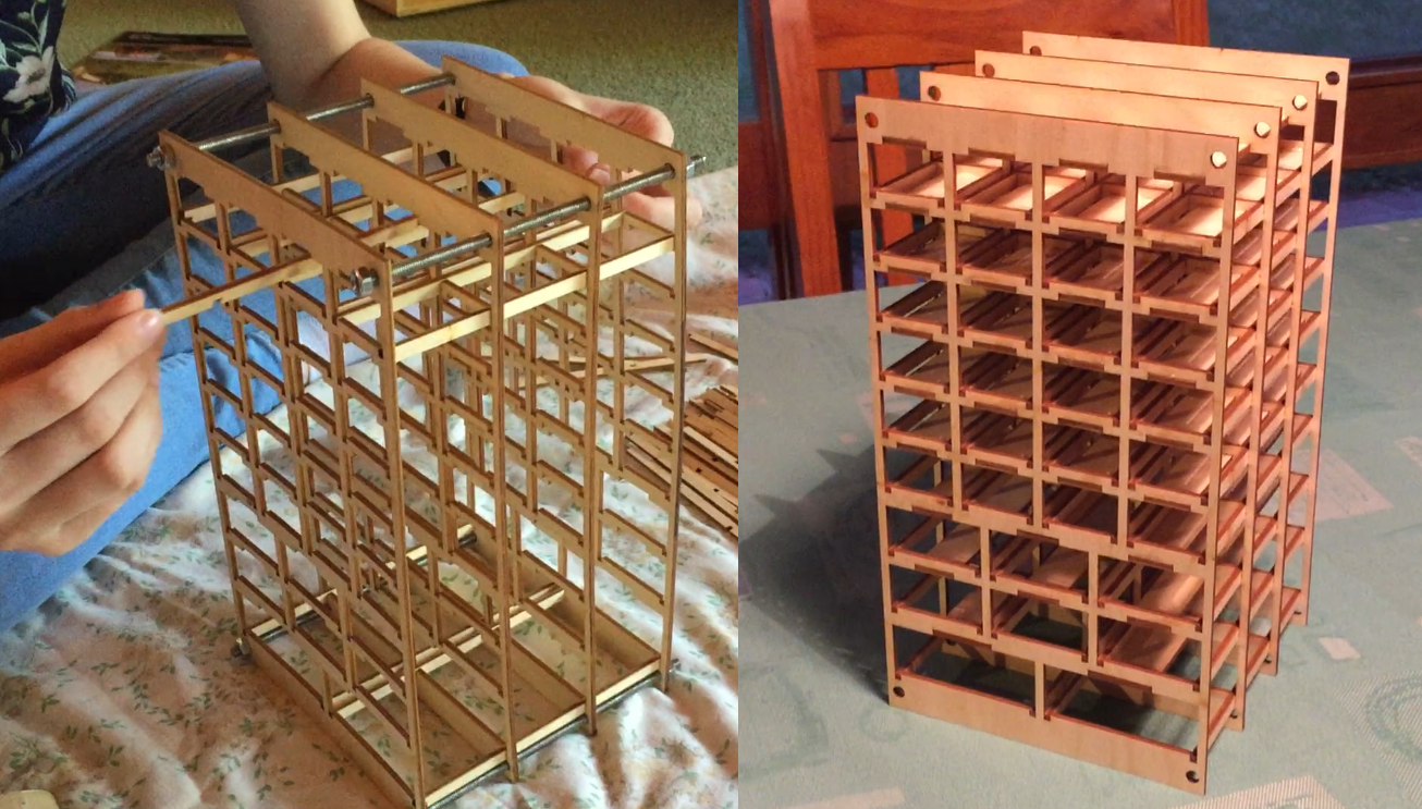
Here you can see the assembly process, with M6 rods through the corners, and the wooden inserts being glued in. It was like a really boring game of Jenga, where you want all the bricks to stay put and the whole thing not to collapse.
3D printing the drawers
Hey, it seems like such a waste of time and PLA to 3D print all of your drawers, why wouldn’t you just get them laser cut? Look, you’re right, however, this was an excellent way to practise and improve my 3D print quality!
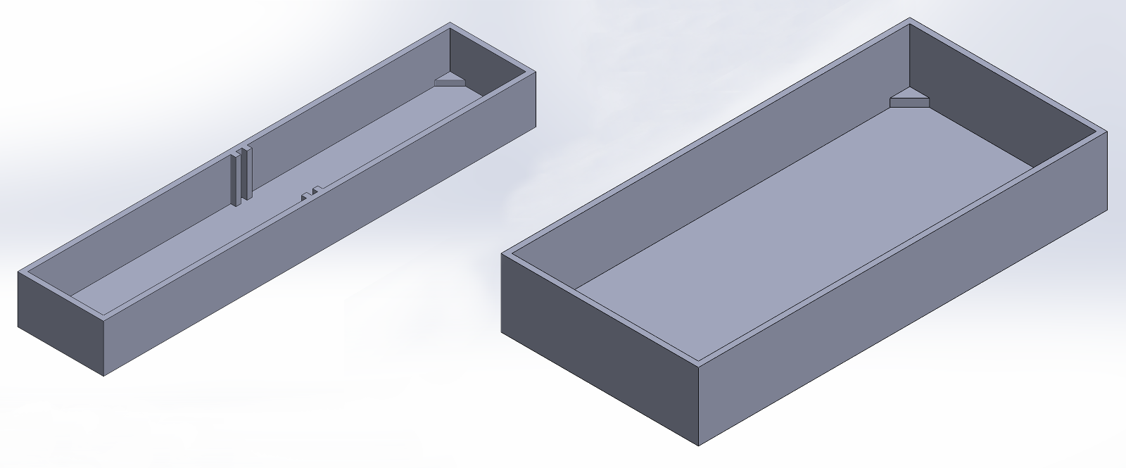
I made some very simple CAD designs for three different drawer sizes, the smallest and largest of which you can see above. For the smaller drawers, I included some vertical rails halfway through the interior, allowing for little separators to be inserted if needed.
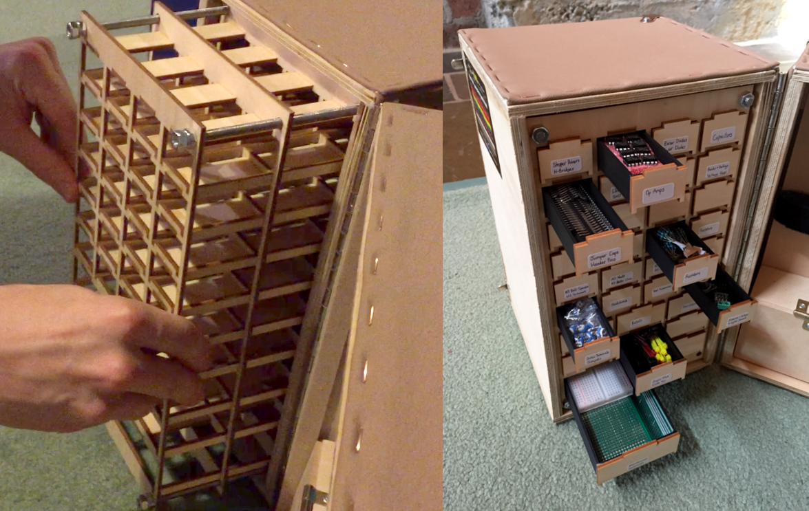
32 drawers later, I installed the chest inside the lab and tried out the drawers. They were very quickly a good fit, and I glued the leftover wooden squares from the laser cuts to the front of the drawers, to keep the wooden aesthetic. I’ll put handles on them eventually. Looking good!
Powered door for equipment
The rightmost door of the lab will house our powered equipment, connected to a powerboard that we can plug into the wall. We want the whole cable and power plug to fit inside the lab as well, so we’ll make room for them too.
Shelf layout for the insertable board
We need to fit a soldering station, powerboard, battery charger, power supply, oscilloscope, LED lamp and a cupboard for leads. Time to play tetris!
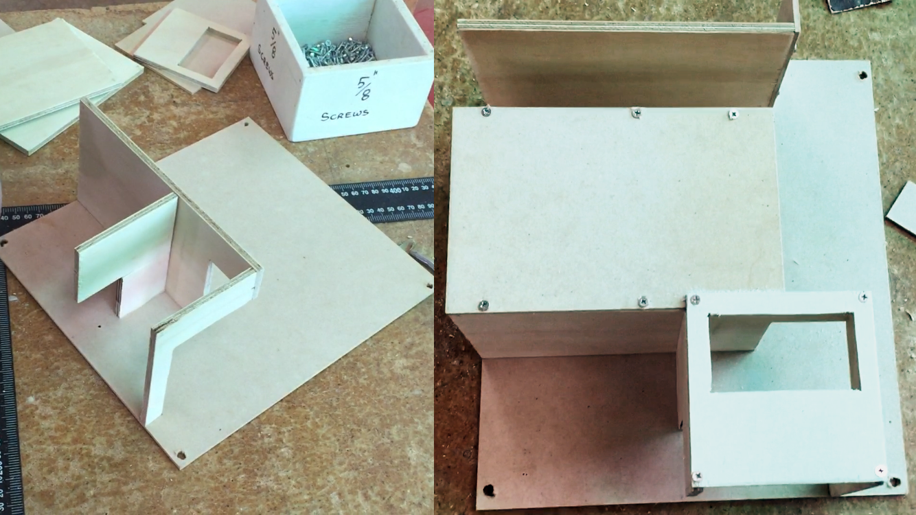
I made the insertable section for the powered door using plywood, and carefully dimensioned it to fit each piece of equipment. The smaller pieces I cut on a bandsaw, and I used a corded jigsaw to cut the rectangular slot for the power supply. This will screw into the backboard of the righthand door with some M6 bolts. But first, let’s get our tools attached!
Wiring the power supply
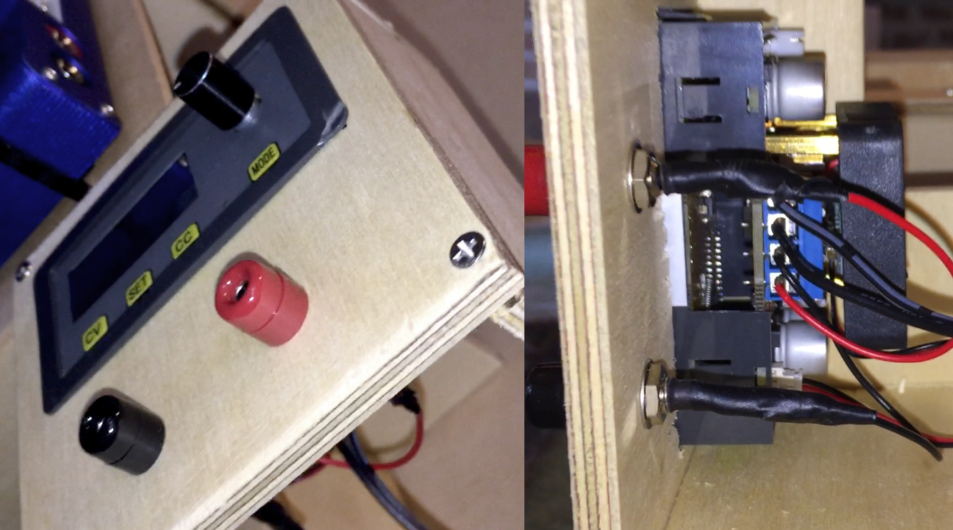
The variable-voltage power supply fit pretty nicely into its slot, and I also drilled holes to mount a pair of banana jacks. These were wired up to a 12V, 1A power supply which plugs into the powerboard.
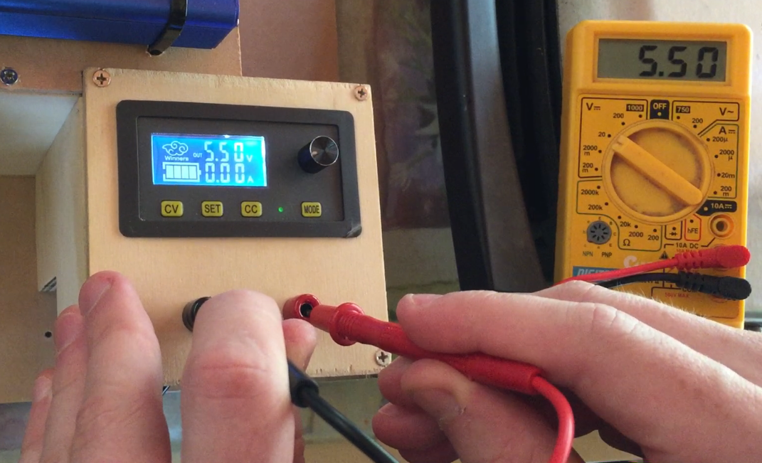
I’ve performed some simple voltage tests and powered a few microcontrollers with the power supply, but am yet to do any serious load testing with it. It was fairly cheap, so hopefully it’ll hold up for my low-power applications. I’ll be careful here – wood tends to be quite flammable.
Assembling and fastening the equipment
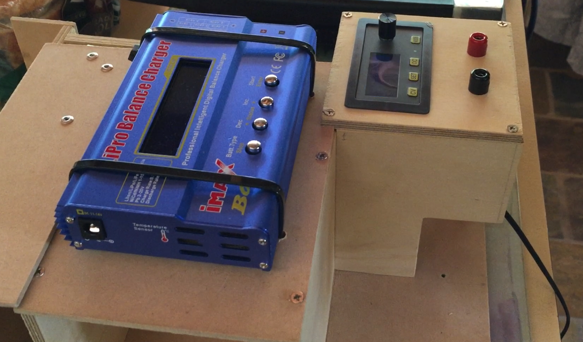
The middle panel of the shelf has plenty of space to mount the Li-ion battery charger, which was simply secured with a pair of cable ties. The power adapter for the charger plugs into the powerboard, and the cables route neatly behind the panel.
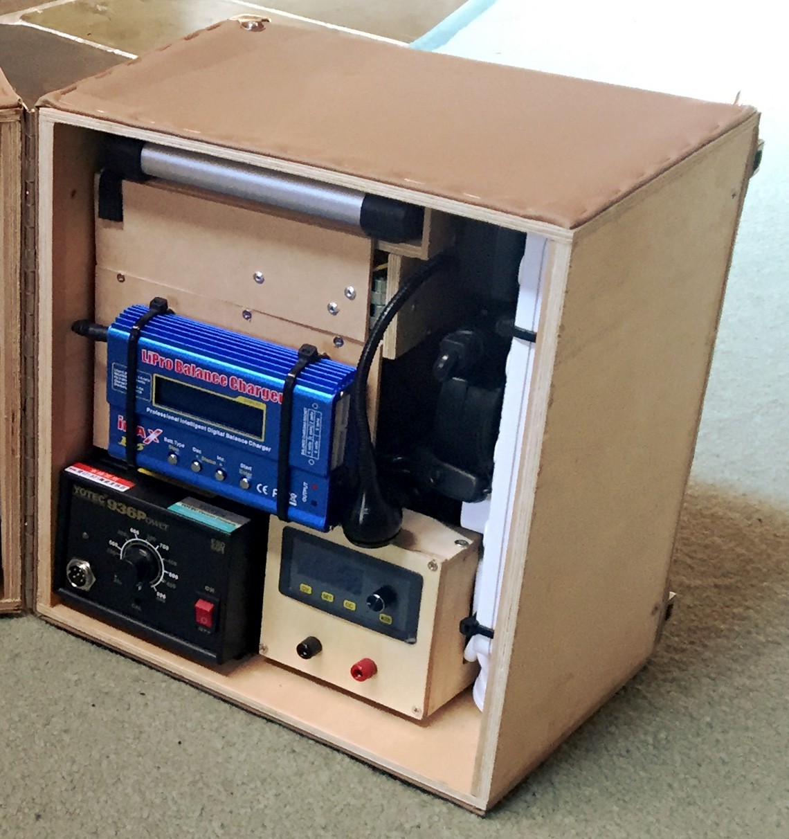
With the powerboard mounted vertically on the right (with cable ties), and the rest of the equipment slotted in place, we’re good to go! The insertable shelves were a tight fit into the backboard of the lab, and have held up very well.
Tool rack
With the powered door all wired up, it’s time to mount our hand tools in the middle section! We’ll do this with a simple, flat, insertable board and some double-sided velcro.
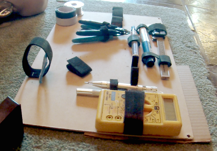
Tool layout
First, we need to work out where everything should go. With all the tools already in hand, it was easy enough to simply lay them down in place and take some photos for reference, after cutting a board to the correct size.
We’ll also add a little cupboard in the bottom-left corner to store consumables such as solder, solderwick and electrical tape.
Adding velcro straps and installing the cupboard
The velcro was cut to a suitable size for each tool, then superglued and stapled to the board in the correct place. The little cupboard was screwed and glued in a similar fashion to the powered shelves, with a small hinge to connect the door.
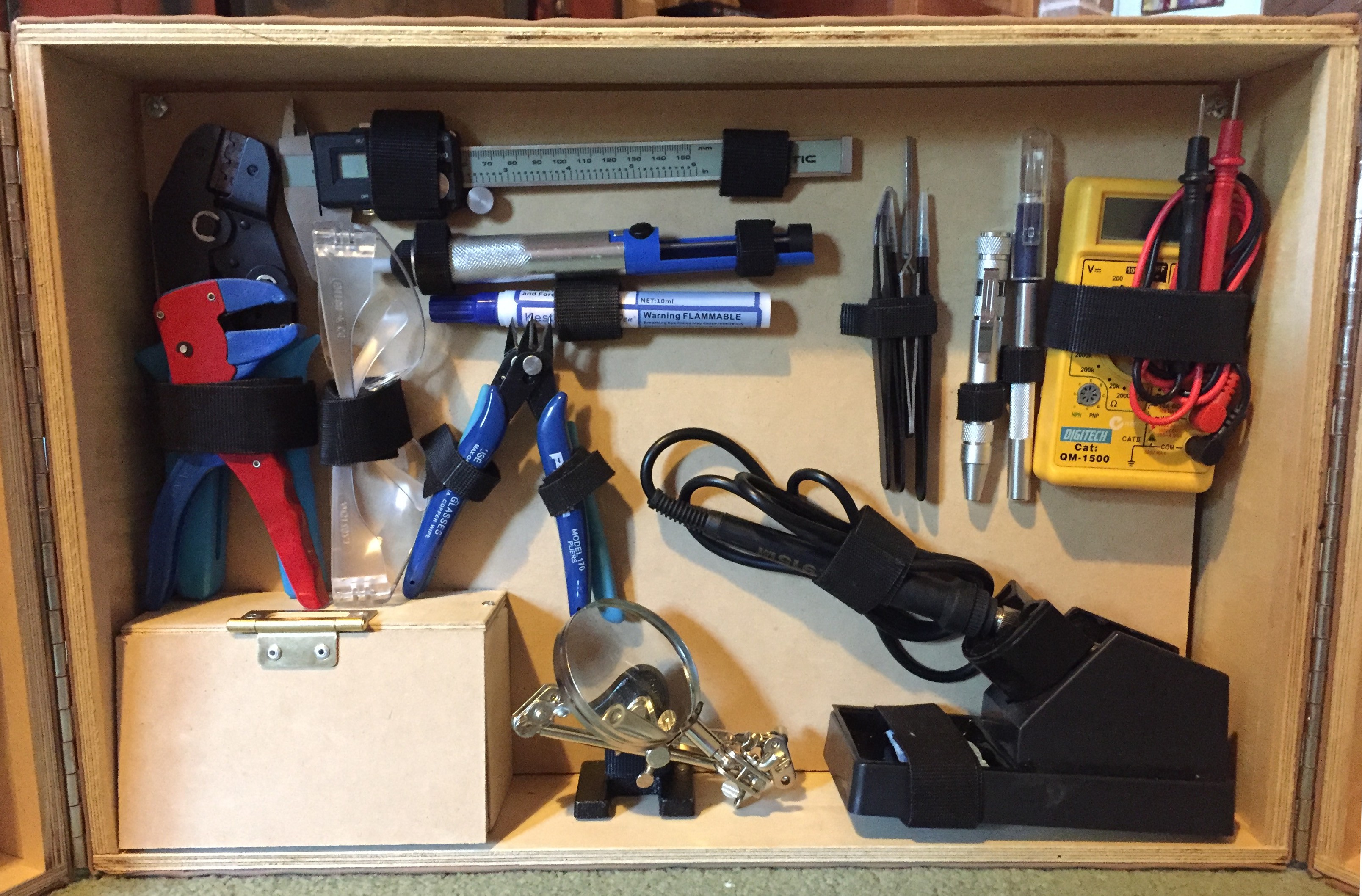
That’s the last of our compartments filled — we now have a full laboratory on our hands!
Making it truly portable
Now, this won’t be particularly portable if we can’t carry it around, so let’s add a handle.
Designing the handle was a little tricky. Since the center of mass of the laboratory is aligned where the doors split apart from each other, I couldn’t simply screw it into the top. Instead, I attached straps at the bottom, which were guided up the sides, meeting at the top with a detachable clip. We can simply unclip the handle to open the lab.
Strap attachment and clamping
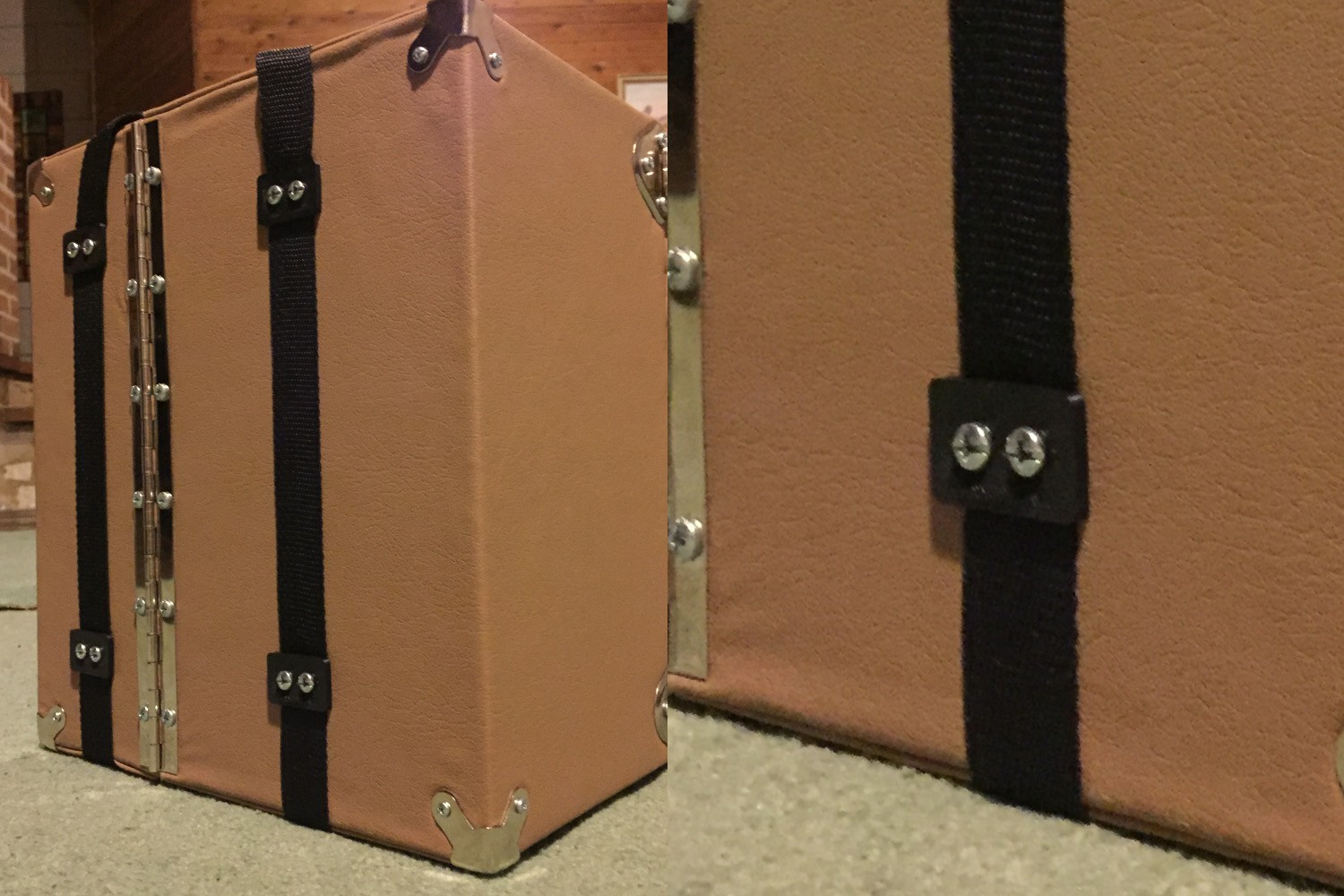
In order to keep the straps held firmly to the walls, I used small double-washers (shaped like an “8”) to clamp them down. The washers themselves don’t look particularly appealing, so I 3D printed some black covers so they would match the straps.
Sewing on the handle
It’s not often that you see electronics, upholstery and sewing in a single article, yet here we are. The easiest way to make the straps nice and strong was simply to sew them together!
The straps were sewn to meet at two rings — one on either side of the box’s top surface. The rings were connected together via a handle (made from the same strap material), with a plastic clasp to allow them to separate.
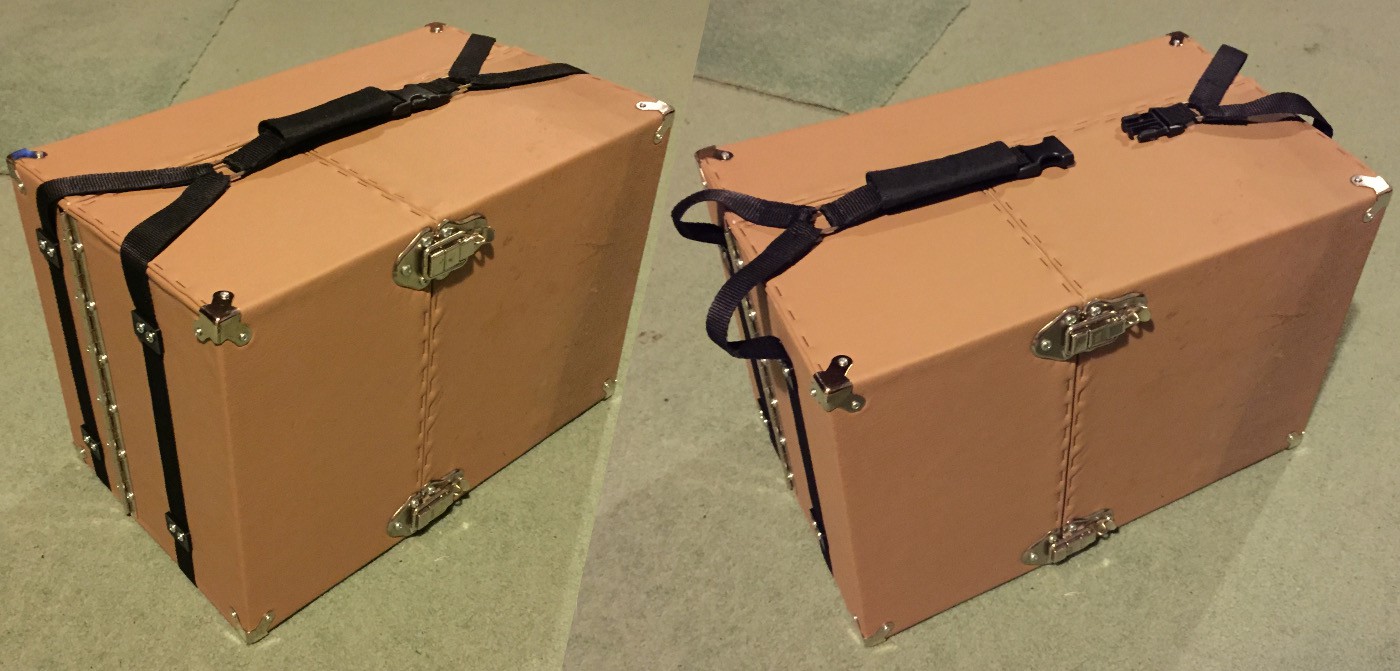
After sewing this together, I added a velcro, padded handle from an old laptop case to make it nice and comfortable on the hand. Our laboratory is now portable!
The PortoLab of my dreams
The PortoLab has been a great success. I’ve used it frequently to work on my self-balancing robot project, to solder up some custom boards, and to perform some non-electrical tasks such as assembling/modifying mechanical devices and cleaning up my 3D prints. It has also been out on a few excursions, including a trip to a friend’s place to work on a little robot. So far so good; the lab is holding up really well, and it’s just as useful as I’d hoped!
Thanks very much for reading. Let me know what you think or if you have any questions!