Close
0%
0%

Simple Digital Mode Transmitter

A low-power, all-digital transmitter.

Similar projects worth following
An HF-band low-power (QRP) transmitter for just about any FSK digital mode.

This is not just another AD9850-based source! Neither is it an FSK transmitter. This does audio tone frequency estimation, which drives the DDS, so that the output is essentially the same as is achieved by upconversion but without doing any mixing, and therefore avoids the need for a bunch of analogue/RF circuitry.

Motivation: I want to play with amateur radio digital modes (like FT8, WSPR, etc.). There are several software tools that can manage all the encoding/decoding, which use the soundcard to generate/receive audio waveforms, but I don't have a rig capable of USB AM modulation which does the translation to RF. (Although the modulation is AM, the resulting waveform is essentially FSK).

I do, however, have an SDR dongle, so I can receive just fine. This project is about creating a general-purpose transmitter capable of any FSK waveform.

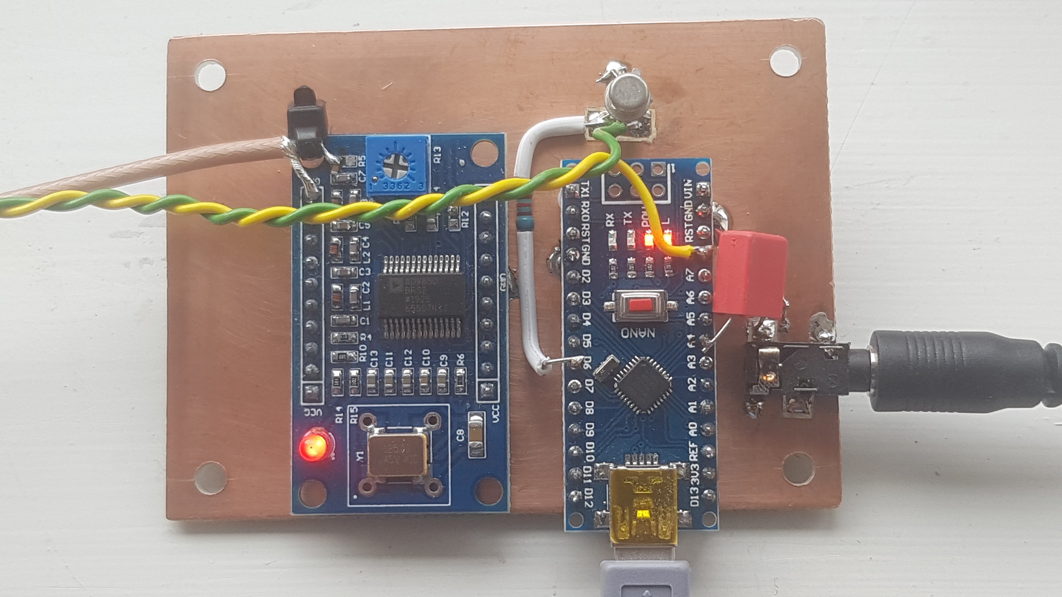
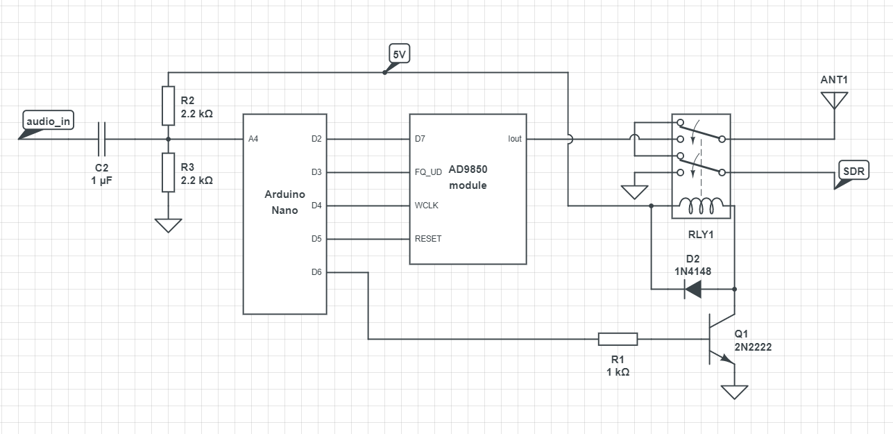
Concept: The AD9850/51 is a cheap and powerful DDS ('synth') which can easily generate signals at all of the RF frequencies I'm interested in, and is agile enough to add frequency or phase modulation. A simple microcontroller (e.g. Arduino Nano) should be able to take the audio waveform from the PC, determine the frequency, and program the DDS accordingly. Do this fast enough, and the DDS should track the audio as the FSK tones change

  • 1 × Arduino Nano (or clone)
  • 1 × AD9850 module
  • 1 × RTL-SDR or similar (only for receiving, not part of the transmitter)
  • 1 × 45W amplifier "530 v303" type
  • 1 × Relpol RM822N-2112-85-S005 DPDT relay

View all 8 components

  • All the best ideas (2)...

    RobG10/12/2021 at 08:24 0 comments

    Looks like QRP-labs have been busy doing the same thing too (plus a whole heap of extra functionailty):

    https://qrp-labs.com/qdx

    Well done them!

  • All the best ideas have been done before

    RobG09/08/2021 at 07:15 0 comments

    Having been quietly pleased about this idea for a couple of months now, it turns out I was beaten to it. I didn't realise but the QRPguys have designed a complete transceiver around the same frequency-estimation FSK technique, that they call AFP-FSK. All the best ideas!

    Would be great to do a comparison of their code and mine to see how the audio frequency estimation accuracy and tracking rates compare, but I don't have the time. Either way, whilst their product is fully-featured, transmit and receive, custom PCB, and with a display and buttons, etc. mine has the benefit of being about as simple as possible (and very cheap).

  • Now in a box

    RobG09/04/2021 at 07:08 0 comments

    The cheapest way, by far, to find a decent enclosure was to buy an old ATX power supply and gut it. A bit of drilling, snipping and filing later and everything fits.

    The complete transmitter installed in an old ATX power supply case.

  • More power!

    RobG08/21/2021 at 13:25 0 comments

    I've been a bit busy gutting and rebuilding my power/SWR meter. It now has all new innards which should give more accurate performance over a wider band, maybe 10-150MHz. The schematic below shows the circuit I used. The two transformers are wound on Micrometals T44-2 toroids.

    Power/SWR meter circuit diagram
    A photo of the fiddly wiring required.

    ...Aaaaand here's a dummy load I threw together to test/calibrate it with. My NanoVNA shows it's good to at least 150MHz (VSWR <1.1), and probably ok to dissipate 10-20W for short periods. Oh, and it has a diode/cap so I can double-check power levels using a multimeter. I've since put it in a sealed tin so that one day I might fill it with mineral oil if I ever need better heat dissipation.

    Yes, that's twenty 1kohm resistors mashed into a heap.

    So with that, I turned up the PA to 2W (oooooh! I hear you cry...). Happy days.

  • Low-pass filter

    RobG07/14/2021 at 09:31 0 comments

    I have now cobbled together a low-pass filter to try to suppress the PA harmonics. This one has a corner frequency of 28MHz (to allow me to use it up to 10m band), using the following components (left to right):

    shunt C: 100pF

    series L: 12T on T37-6 core, making about 485nH

    shunt C: 180pF

    series L: 13T on T37-6 core, making about 580nH

    shunt C: 180pF

    series L: 12T on T37-6 core, making about 485nH

    shunt C: 100pF

    28MHz LPF

    Performance simulated in LTSpice, and then confirmed with a nanoVNA. I'm now feeling a bit happier about winding the power up without annoying the neighbours...

  • And we're off!...

    RobG07/04/2021 at 10:38 0 comments

    Finally had a chance to get the PA up and running, add variable output power control to the DDS, and connect the two together. Everything's working very nicely and I can now easily adjust output power between <100mW and 10W (and more). I bought an old (and very sickly) power/SWR meter, and calibrated it to 10W, so at least I have a rough indication of power level.

    All the bits hurriedly lashed down to a bit of ply - not pretty but it works.

    No output low-pass harmonic filter yet, but harmonics are approx. -40dBc at second and -25dBc at third, so probably won't cause too much interference. For now I'll keep the output power to around 1W to be on the safe side. Actually, the old 12V lead-acid battery I'm using to power the PA is knackered so most of the time I'm probably only making half that...

    On my very first FT8 transmission I got a QSO - so clearly it works! And now getting spots well in excess of 5000km on FT8.

  • Get smart

    RobG06/20/2021 at 15:00 0 comments

    Took a little time to transfer the Arduino/DDS circuit to a bit of copper-clad board but I'm glad I did because it looks much neater.

    Still regularly trying it on 20m, 15m and 10m bands, using WSPR and FT8 modes. Regularly hitting 900-1000km using WSPR, but almost no luck at all on FT8 (unsurprisingly). Really must get that PA finished!

  • First look at the PA

    RobG06/17/2021 at 16:39 0 comments

    Was in the office today so had a chance to run up the PA on the bench. Having first carefully set the MOSFET bias so that each was passing something like 25mA (according to instructions here), I could then adjust the drive levels to get a nominal 10W out. Then, sweeping the frequency in bands (4-8, 8-16 and 16-32MHz) the plot below shows how the output looks, including harmonics:

    PA output, whilst frequency is swept - max hold on.

    Clearly the output power isn't very flat, but conveniently for me it peaks at about 14MHz (20m band) which is where I was intending to use it most. Third harmonic is the worst offender, at about 23dB down, so a filter is required on the output - no surprises there. Would be good to get the 2nd harmonic from -33dBc down to <-43dBc, so then I'd only need a single LP filter (with corner=28MHz) to cover all the bands from 20m to 10m and still meet "the -43dBc requirement"*. Will see if I can tweak the MOSFET biases to achieve that.

    The real shocker was the drive level required: only -27dBm! (at 14MHz). I might just bypass the first stage as I definitely don't need all that gain...

    Lastly, this: (14MHz, 12V supply)

    Pout (W)last stage current (A)Efficiency (%)
    10.7411
    21.0915
    51.7524
    102.5333

    I'm hoping a simple moving-coil ammeter on the PA supply will be enough to give me a rough idea of output power.

    *interesting that the UK requirements seem to be much more relaxed: "...as free from Unwanted Emissions as the state of technical development for amateur radio apparatus reasonably permits"

  • A bit of a surprise...

    RobG06/11/2021 at 18:39 0 comments

    I finally got into the office today and had a chance to put the transmitter on the bench. First job was to swap out the filter components - though actually the new filter isn't that great either (the roll off needs to be steeper) so I might change it again one day...

    Output power measured on spec. an. (CW swept over 1-60MHz, max hold on)

    But the next thing was to measure the output power: a measly -2dBm! Barely 0.5mW! And that's after I changed Rset for a 2kohm to increase the output power. No wonder I'm struggling to get the signal out...

  • Switch it around

    RobG05/25/2021 at 13:43 0 comments

    Replaced the TX/RX relay today. Was previously SPDT, now DPDT configured so that the RX port is shorted to ground during transmit for a bit more isolation. When I've got a 10W PA hanging off the other port, and only 10mW (1000x less) into the receiver will damage it, I want to be very sure that I've got all the isolation I can manage!

    Relay is a Relpol RM822N-2112-85-S005. A quick look on my VNA shows >60dB from DC to 50MHz. That'll do...

    Here's the circuit so far:

View all 16 project logs

Enjoy this project?

Share

Discussions

Aaron Jaufenthaler wrote 07/14/2021 at 11:53 point

Thanks for sharing. Congrats for the nice idea and build. 73 de IN3EDA

  Are you sure? yes | no

RobG wrote 07/14/2021 at 12:36 point

Glad you like it. I'm quite pleased with how it's turning out!

  Are you sure? yes | no

Similar Projects

Does this project spark your interest?

Become a member to follow this project and never miss any updates