 Eric Hertz
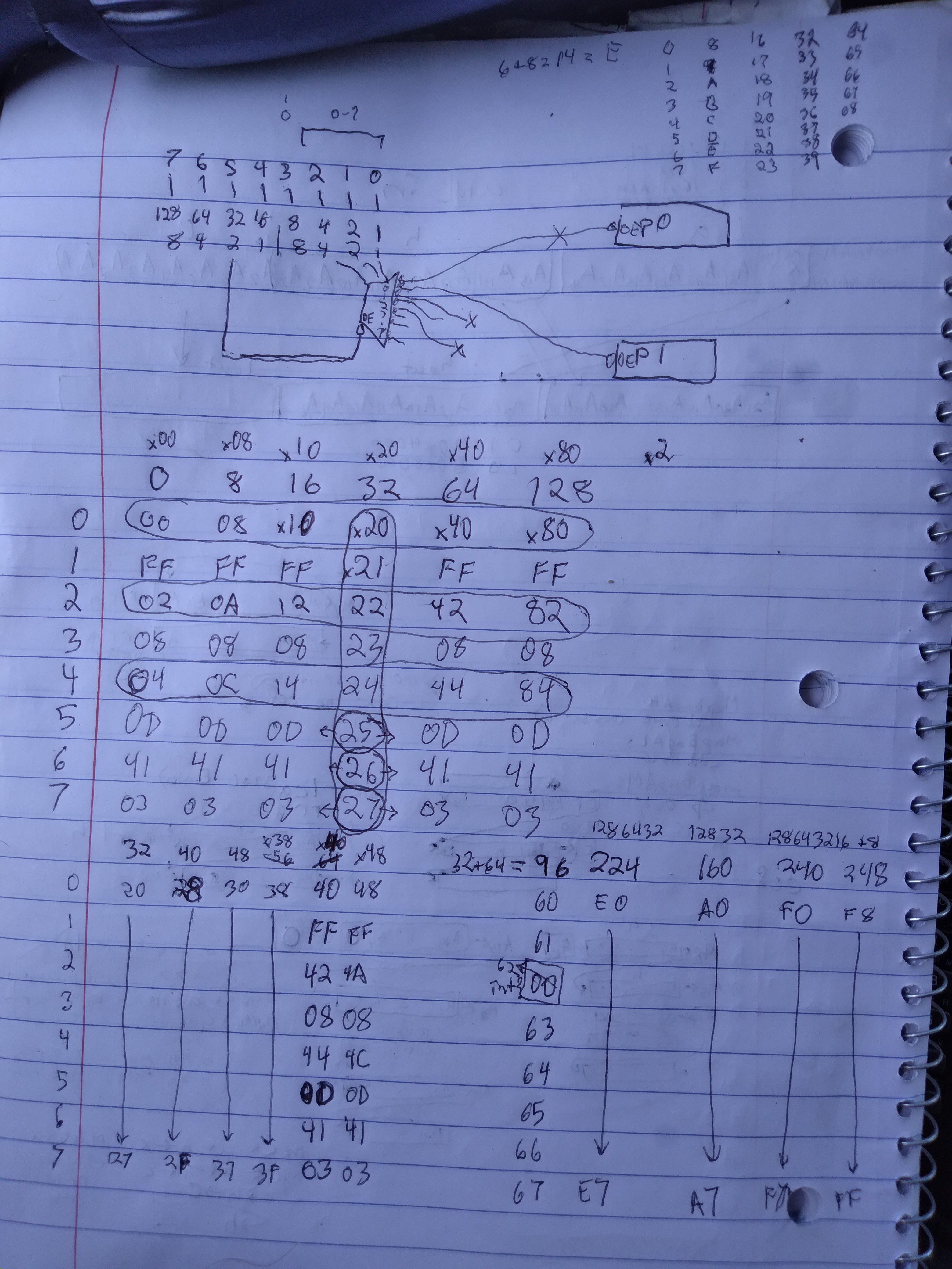
I decided to do a port-read of ports higher than the 8 reverse-engineered and documented by others. I found something interesting... while mostly they seem to repeat after every eight steps (which would make sense if they just used a 3in-8out demux) they /don't/ repeat if bit 5 in the port-address is set. So, it would seem, the 8out demux has a low-active output-enable tied to bit5 on the address bus. Now, why would they do that, I wonder?
Note that when reading a port that is write-only you read back the port address... my guess is that is on the data-bus due to capacitance holding the last op-code, which was the port address.
But note, again, that the pattern of repeating the first 8 ports begins again when bit 5 is low, even, e.g. with bit 6 or 7 high.
Am thinkink maybe there's room for 32 user ports (32-63), or some other write-only port in that range.
So, then I looked into the reverse-engineered T6A43 pinouts, combining them and my work, to see if there's room for an I/O select pin... maybe it's only output for ports in that range...
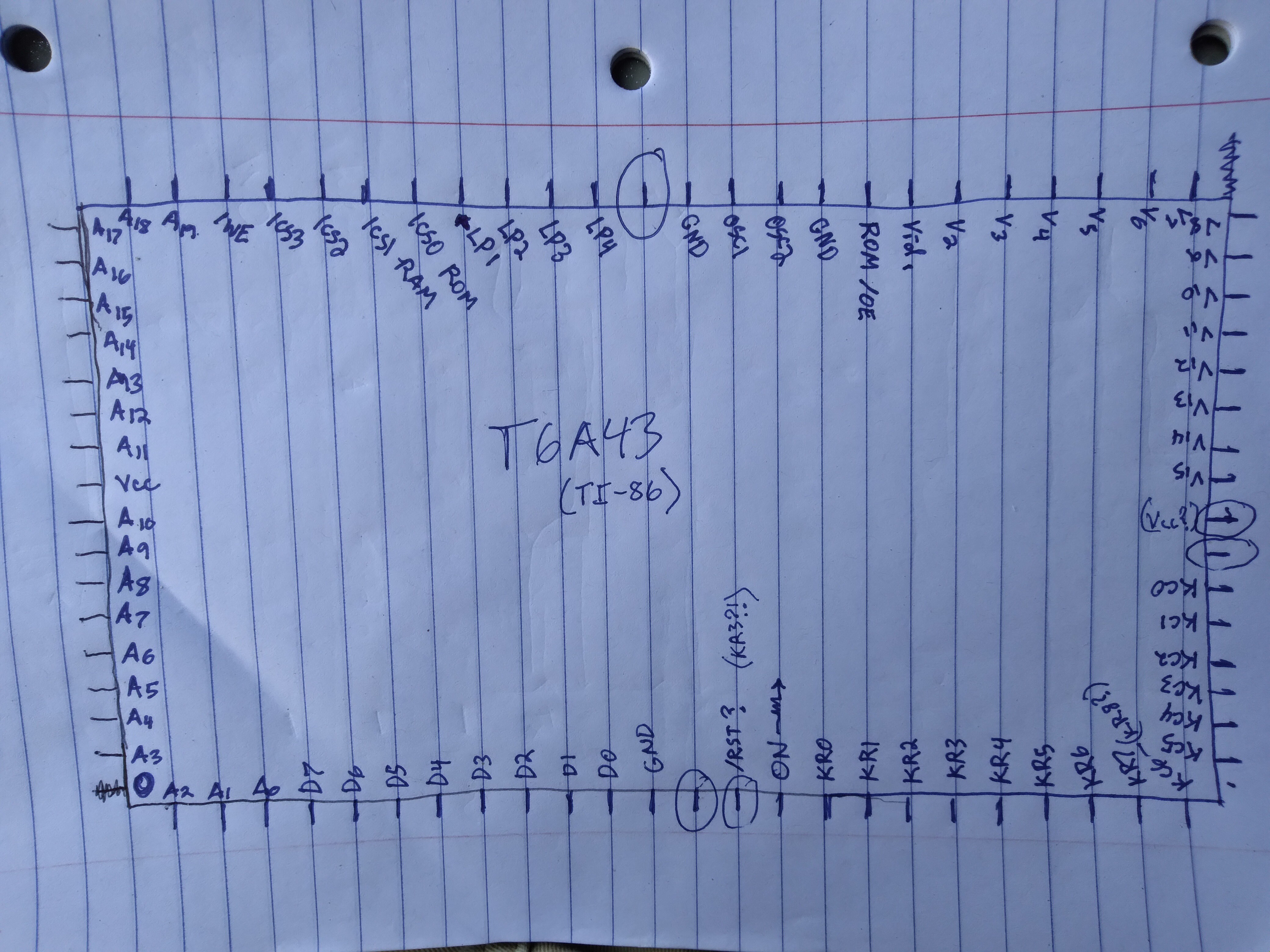
There are five pins which aren't well-accounted for... I tried to follow traces, and as I recall none of them are no-connects. I believe those reverse-engineers probably scoured the disassembly of the ROM for ins and outs, based on how they described their findings, so I kinda doubt port32-63 are accessed... (hmm, maybe I could grep the hexdump?). So then that leads me to wonder about how something like /IORQ could be [mis]used for other purposes.
/MEMRQ isn't really necessary, it could be presumed when /CS0-3 are active...
HAH, that could very well be it... maybe not a specific pin for /IORQ, but a NORing of /CS's... though, it would require the A21-20 to /CS3-0 demux's /OE to be wired to some logic with /IORQ as an input... sure, why not...? In fact, plausibly, of course it might be.
Wherein, maybe, even if /IORQ /isn't/ broken-out on one of those undocumented pins, it might be hackable anyhow. Hmmm...
...
But, I wasn't really looking for external ports, was looking for internal ones. Was kinda hoping the timer used for interrupts at 200Hz(?) had its count accessible somewhere, for precise timing of events. Kinda surprised I haven't found it yet.
And /that/ endeavor was started by the idea that I don't really care to learn about TI's variables, nor do I trust my wonky 100B/s link setup to work reliably for the 45minute download... so looking for other means to transfer the FLASH chip's original contents, which is kinda a stupid idea since I have no idea what it's from... OTOH, all this may lead to more/better understanding of the T6A43. Oh, the idea there was maybe to bit-bang regular ol' serial... which, realistically, might be pretty slow since the CPU clock speed may vary significantly... And, even without a high precision timer, the same could be done with cycle-counting, if necessary.
Anyways, obviously sidetracked.
Any benefit to using in/out over just memory-mapping? Reduced decoding logic, i suppose... No need to remap... yeah, it could be handy. I could maybe even implement my fast-access/no-remap 24-bit addressing scheme idea... though, that'd require enough rewiring to likely justify a fresh start with a "real" z80. Oh, also difficult since remapping A15-14 happens internally.
Knowing me... I'll probably be looking into this port32-63 thing further.
... hours later...
Searching the ROM image for outs that're hardcoded directed to a specific port... we have what seems a first match (after 0-7)... port 0x45. Could it be? It's not in my bit5 rationalle... but, what is this port 45???
Which gets me thinking... port5 is the "ROM" mapper... port 0x45 might just access port5 through wraparound AND give an extra bit or two. E.g. writing a value to port5 maps a specific setting for addresses A21-A14 to map to 0x4000-0x7fff... but, what if there really was an A22, maybe even an A23...? How would one choose them via an 8 bit port whose data bits start configuring at A14 (e.g. port5)? What about using one of the port address bits /as/ the value? A 10bit d-ff register/latch could be addressed by A2-0, to select port 5 of max 7, for writing the first 8 bits, and the remaining two(?) bits on the 10bit latch are written low. BUT... since thus far it only pays attention to A2-0=5, what happens when e.g. A6 is active? It wraps-around? So writing port 5 is identical to writing port 0x45? But, wait... those extra address bits could be put into the higher bits of a /TEN/ bit register. E.g. write at 0x05, get 0x00-0xff, if the next address bit were connected to D9 on the 9-bit register, then writing to port 0x15, through wraparound, would do the same as 0x05 AND set the ninth bit in that register. 0x25 would set the tenth, 0x35 would set both the ninth and tenth. Why not? Actually, this logic is quite similar to the 24-bit addressing scheme I came up with... use the same port latch at multiple port addresses to load it with more than 8bits of data. HMMM...
I've yet to look at the surrounding code to see what it does...
And, as an apparently WriteOnly address, it's a bit confusing... and adding to that... what was it...? Oh yeah... what would those higher address bits actually do? I'm pretty certain the two highest bits in port5/6 address the chip-selects... but what would an extra bit, or two, address?!
Their only existing in two locations (outs to port 0x45) suggests it's RARELY used... maybe for the ROM /OE which is only ever deactivated during FLASH writes, which is only used during devel... it could be....
...
Needle in a haystack, heh. I'm still digging for some in/out to an undocumented port... 0x45, it appears, isn't a thing... one is definitely a jump address through the very interesting function I wrote about in a previous log. The other must also be in some sort of lookup table, because most of the surrounding data doesn't make sense as instructions (e.g. ld a, e; ld (hl), b; ld a, e; <---why?), and lots of it.
@ziggurat29 wrote of something similar a while back... I've learned a lot from his disassembly work both about the TI-86 (and Kaypro) and also about sleuthing disassembly in general... I'da been like (was like): "oh hey, that 'out (45), a' isn't changing, no matter where I begin disassembling surrounding opcodes! It must actually be a thing!" ... but only after: "how the heck is disassembly even possible, without knowing which bytes contain the beginning of an instruction?!" and so-forth. Ziggurat29's shared a wealth of knowledge burried in comment-threads in logs, often of tangentially-related topics, around this project and #OMNI 4 - a Kaypro 2x Logic Analyzer . Heh!
So, this time around, I knew to look for "reasonable" instructions surrounding... and, through his example I can see it's really not particularly reasonable to do a whole bunch of byte-copies back-to-back, which overwrite each other without /doing/ anything with any of that copied data before it's overwritten (sometimes with itself!), nor doing anything with flags, etc. So, my guess is this is a lookup table of some sort, or otherwise stored /data/ rather than /instructions/... which brings me full-circle to seeing first-hand how to disassemble when there's no way to know where an instruction starts... the answer, I guess: a lot of guessing and checking and knowing some tricks.
Thanks for the insight these past years, my friend!
...
As far as using wraparound for e.g. port (5+n*8) being used to write extra bits to port5... that doesn't seem to be the case, here, but I like the idea, maybe for my own designs. Anyone seen it elsewhere?
...
Oh yeah, "online disassembler"... hah! The first time I came across it, I couldn't imagine how it could possibly make sense to have a website for something like that... I've used it A Lot, since... on my phone, exclusively, no less. This is a strange era!
...
Oh, LOL... I coulda probably guessed this was a lookup table by noticing the surrounding bytes have a pattern... 0x44 (and similar) is repeating every two bytes (look at the line marked 49194(byte offset))... also, the other byte paired with them seems to, for the most part, be near in value and increasing... this could be a jump-table, or 16-bits used for a table of sin(), or so-forth. Though I'm leaning toward ROM jump-table, since 0x4400 is in the mapped-rom section.
....
Near Byte offset 39482 (decimal) there's a potential out to port 40...
Is this a fool's errand?
It's /only/ an out if you start the disassembly /at/ the out instruction... which would mean it jas to be called or jumped- 2 1s ldirectly. I'm in too deep, at this point, to keep track of all the branches I've gone on, and how to continue with them, looking to legitimize this as an actual out to 40... but, the latest (and I think as deep as I'm going, here, unless knowledge of some amazing trick comes my way) was to grep the entire binary of the ROM for calls to that out 40, directly.... (I have no idea how to grep it for relative-jumps, etc.) If I did my math right, the call would consist of the raw bytes, in reverse order, of its address bytes, when mapped into the rom-mapping page, of 9a42h.
Which... i don't see any calls to.
But, why have I gone this far if it's the /only/ out 40 in all of the ROM? And further, only /actually/ out40 (as opposed to, say, a couple address bytes in a call/jp, or even a couple bytes in a lookup table) if you call/jump to it explicitly? Maybe it's just wishful thinking, trying to uncover some hidden feature that could be made use of, or trying to confirm my theory that designers might use address bits (bit 6, here) as a means of entering additional data bits to a port...
but there /seems/ to be some plausibility this could be the real deal, despite so many specific requirements... if you start disassembling /at/ the out40, the code thereafter makes sense, whereas starting disassembly at all the byte-offsets I tried /before/ it seem somewhat nonsensical except as a jump table... WHIC would suggest we're in a jump-table, right? But, /immediately/ after the jump instruction containing the bytes which could be an out40, the jump-table seems to end. And the instructions thereafter don't make sense. Whereas, treating it as an out40 which has to be called/jumped-to directly, the instructions thereafter do seem to. Soon thereafter is a jp z, as I recall, which would rely on a and the flags being set prior. Kinda like arguments to a function call. Again kinda making sense. And after following that jump, we're led somewhere that /also/ looks like legit code one might jump to...
I didn't follow that rabbit hole much further, as, the number of branches and ROM calls got overwhelming... but, that's where I decided to grep for calls to the out40... and found nada. So, now, it seems a bit less likely (than even the amount of unlikely this endeavor started with!). And, again, I have ziltch ideas for how to grep for relative jumps, etc. to a specific location.
BUT:
Let's pretend it could be... what could it be?
Port0 maps the framebuffer. Why is that even changeable, I dunno... seems it's very hard-coded (based on my readings... I haven't looked at out0 code yet) to always be at the top of the always-mapped ram page. Here's an aside-oddity, reading one of the reverse-engineered port-description documents, they claimed that TI-OS writes a value to port0 which doesn't seem to fit into their determining of its functionality, /unless/ a couple of the bits explicitly set high are masked in the end... could be... but why write them 1? Sometimes that's "good practice" for bits reserved for future disigns, but the T6A43 is a VLSI that,'d been around for some time... doesn't seem another version was coming... and, other calcs from TI of the era were based on different chips altogether... e.g. the TI-83 has a dedicated video-controller chip with internal RAM, not sharing system-RAM /as/ the vram. Anyhow, so maybe that port has more functionality than has been discovered... maybe a lot more.
E.G. how does the OS handle the fact that there are two separate screens whose contents are kept when switched to the other...? There's /at least/ the "home" screen and the "graph" screen... when at the home screen, is it using a different framebuffer location, or is it actually like on an old PC using a realtime character-generator synced to the screen pixels' being loaded? Such a character-generator /could/ be used, instead, to load the framebuffer... but if it did that, then we'd need two framebuffers to maintain the two screens. I've yet to learn of such a second framebuffer... but that doesn't mean it doesn't exist. And the fact that there's a port dedicated to changing the framebuffer location suggests there might. BUT: again, I don't recall reading of this second framebuffer, which I think would've come up in the "free memory locations" documentation... since, e.g. when playing a game (in the "graph" framebuffer) one might not be too sad to lose their graphs and their math on the homescreen... 1024 bytes is nothing to scoff at. So, now, what if the framebuffer-offset port has an additional bit (e.g. by accessing port0 through port40) to choose to map it in from (or the unused one out to) /another/ RAM page? I THINK the majority of the circuitry to do-so would basically already be implemented through port0's functionality, as understood, currently. So, it'd really only be a matter of, essentially, an additional remapping 8(?)bit latch, just like the other two (at port5/6)... So, frankly, I could be totally wrong, here, it could very well be that the mapping scheme could have portions of five different memory pages accessible at once...
Hmmm.
And it may be a matter of one function call to switch the framebuffer "page" in and out, based on the zero-flag (or was it carry?).
Anyhow, that could be groovy... Presently, as I understand grayscale, it's done by switching between framebuffer offsets... that means three shades of gray would require 3096bytes of RAM, /in/ the always-mapped RAM page zero. Which is pretty much necessary, anyhow, because if you want to change one pixel you've got to change it in three locations... but what about this possibility the framebuffer could be in another page entirely, and switching that in and out? Doesn't seem so handy to have to switch it three times just to change one pixel... nevermind doing-so in synchronization with the frame you currently want displayed...
But, then... if it's switchable to a page other than 0... /that/ page could be mapped-in (constantly) at 0x8000, now all three framebuffers are writeable without swapping pages, and they don't have to occupy RAM page zero... leaving plenty of permanently-mapped RAM for other things, and ... i lost it... something about the idea of having a means to transfer 1024 bytes of data between two ram (or other) pages without swapping back and forth, nor unmapping the ROM jump-table. I thought i had something more interesting than that...
Anyhow, it /could/ be, and, really, with minimal extra circuitry, suggesting it might be... which, even if it's not, gives me more ideas for my own embedded/computer (z80?) system designs, if i ever get around to something like that.
...
Then there's still that ROM /OE... which happens to be right next to the video pins... so, again, plausibly controlled by port0. Which, again, might be accessed via port40... which would help to explain its only being accessed in one location. Though, there seems to be a "ROM Disable" on one of the ports, which would make sense to control the ROM's /OE, but, as I recall, that was documented in the TI-85's ports, wherein, as i recall, according to the reverse-engineered schematic, is elsewhere.
I am /way/ off-course, now... what was my goal? Oh, hopefully find a timer count... so why am I looking at OUTs, instead of INs? Heh. But, wait... why do i want a timer? Oh yeah, (besides being all-round handy) to bitbang serial data... and why that? To back up this stupid flash chip I pulled from some unknown PCB I deemed more valuable probably two decades ago as spare parts for a project like this one, one day... heck, for all I know it came from a particular (quality) model ISA modem I have /several/ of, which haven't been scrapped. Didn't I have a goal before that? Oh yeah... back up to flash the TI-86 assembly code I plan to work on, regularly... (why not get a USB link cable?) 'Pop goal' to add some groovy hadrware and figure out cool possibilities, 'pop goal' to learn some z80 and Von Neumann, 'pop goal' to get back into projects, 'pop goal' hrm... see if/how/where I can ... oy... and to keep my mind off... gah... and so many other things.
Back to "work"!
INs... I should be looking for INs at weird ports.
...
For a bit there, I thought a couple things: A) maybe, this being a VLSI designed around a z80, they had "blocks" to "drop in" that were specifically designed to work with Z80's... e.g. isn't there a whole set of chips for various peripherals? Right: Z80 PIO, Z80 CTC... and B) maybe the CTC (Something Timer Counter) didn't actually support read-back of its current count-value... e.g. maybe it was intended purely for periodic interrupt generation. But... no, it doesn't look that way. Simply read its port, get the count value back... as I've been trying.
So, then, I finally got around to reading /every/ port (0-256) and pretty much found exactly what I'd already found... the 8 ports repeat every 8 ports, except when bit5 is active in the address. This time, though, rather than reading back the port-number on read-only ports it's instead reading 0x78. Which took me a second... oh yeah... the thing that made this possible was something I assumed there from the start, but got a compile error... that's trying to use a register to select the port. And, apparently my compile-error was due to trying to use register a. If you want to select a port number via register, you gotta use c. Heh. Found that when looking for what byte sequence to grep... so, now, i suppose there's potential for really difficult to grep port accesses via register values. And 0x78 is due to the instruction byte sequence for reading a port selected by c, which seems to confirm the earlier port-number-readback theory: the last instruction byte remaining on the databus via capacitance since nothing else is driving it.
Yes, I filled /most/ of the table by typing each port number, previously. So, finding in a, (c) is opening new doors... like... when using those register-selected-port-number instructions, a side-effect is that b is loaded to the high address byte. Typically it's "supposed" to be ignored by I/O stuff, but actually it's well-documented-enough that some z80-based designs use it... hmmm
Allegedly the ZX Spectrum used the high address byte to scan the keyboard matrix. Clever. So, then, it's also plausible for some crazy reason the timer/counter value is at some imaginary port between 256 and 65536... but probably not one whose A0-2 are high, and maybe likelier (as if this is likely at all) one whose A5 is high. Thankfully computers are /really good/ at iterating through loops. I, however, am not quite grasping how to write such a thing in assembly... because, in addition to needing the two nested loops, I don't plan to scroll through 10,000 pages of values. This thing's gotta look for something unexpected, and show me only those cases. And so I thought (IX + n) was the way to set a starting address to compare to, then calculate n by masking out bits other than 0-2 in the loop iterator/port-number... but... no... n is a friggin constant! What?! This ain't for iterating through arrays, it's for selecting items in a struct. Sheesh. So, I guess I've gotta do a lot of math, in assembly, with ever decreasingly-available registers... heh. This is definitely a different way of thinking than my decades of C.
The odds of this finding anything seems /really/ slim... but it could be interesting. Today I couldn't shake the feeling I'm panning for gold... but I also can't seem to shake the urge to continue this quest despite decreasing odds.
"Maybe it has to be activated, first, through some other port"... heh... the list of maybes seems to grow with each "nope".
But, really... how the heck ya gonna put a counter in a processor and not make its cout readable...? I mean, really...
...
The ROM Disable bit is documented for the TI-8/6/, after all. Could it really control /OE? There's also a RAM disable bit, which allegedly works (how on earth did they test that?) But, the RAM has its /OE tied to ground, not the CPU, and that wouldn't disable Writes (which, of course is irrelevant to the OTP PROM)... the only other way to disable the RAM is through the chip-selects... and that'd work, too, for the ROM... and there are two more unknown bits in that port which maybe disable the other two chipselects... but they're in a very weird order. So... next time I get out the logic probe, maybe. But, if it is at the chipselect level, that could make for some other hackery, like the idea before of using no-chips-selected to indicate an IORQ, or control yet another 1MB of memory... or, maybe it disables only the /mapping/? I dunno.
I'm a rambling man...
...
Holy sh**, CISC IS INSANE!
One friggin' instruction does all this?!
I see, now, this project has more to do with learning [of] the insanity that is CISC, than anything else I'd planned.
So, one more time... the goal was to reduce the amount of data storage and bus accesses used by instructions, right? I mean, now I can see how substantial those savings would be. Two instruction bytes for what would easily take 10 on an AVR!
I can't quite wrap my head around the implications...
Writing in C, these things are hidden... Writing in AVR assembly [inline, in C] is something I've done, oh, probaby far less than 50 lines of, at most in a project. It's a bit frustrating how much extra work it takes to do simple things like var++, but there's a simple enough process to it. Load var from ram, increment the register, write back to ram. But, looking at this... holy crud. No wonder higher level languages took over... who can even remember /that/ an instruction like this exists, nevermind which registers it works with, etc? Props to CISC assembly-writers.
Meanwhile, it's got /that/, but if you want to use a register to choose a port number, you can only do-so with register C. Heh!
I suppose those sorts of things would be easier to learn from a more verbose assembler. ZAC, to keep it small enough, merely says "error at <line>". Having a printout of the assembly manual is a good idea.
As far as what that means for my path... well, full-on z80 assembly guru isn't what I had in mind. If I need something like this instruction offers, I'll most likely be completely unaware of its existence and code it step-by-step as though it was RISC...
But, doing-so keeps surprising me, where some of those core simple instructions have such weird limitations! You /can't/ use register a to select a port number?! A's The Guy! The Goto. The one that works where no other will! Think: cp, and, shl... alright, I get it... port number is more like an address, a isn't usually for addresses.
It's kinda interesting stuff, but I've got goals, man! That's why I'm searching for a likely non-existent port, right? Well... longterm if I found it it would align with later goals quite nicely...
Heh. OTOH, later goals are "add functionality/hardware!" So, I guess, adding my own counter for timing purposes is along those lines... hmmm... would I go the z80CTC route, or 7400-series? The latter being tiny in comparison, might actually fit in the case. My needs aren't huge... just need to keep a running count at some regular interval faster than 10,000 counts/sec... don't even need it to interrupt when it overflows as long as it's checked once per cycle... which the 200Hz built-in timer interrupt could do... still, at 2MHz (cpu clock's prb faster), that'd have to count to 10,000... 16 bit counters aren't exactly common in 7400-series. In fact, I've long searched for even 8 bit counters. Hmm. But a DIP40 for a friggin 16bit counter seems a bit much in the available space. An alternative, maybe, is an RTC... do they have those with high precision taps?
I'm not sure if this is the sorta addon I had in mind, though... If I do add it, and /much/ of my coding-style (e.g. in #commonCode (not exclusively for AVRs) ) makes use of it... then that means anything I come up with that relies on it would not be usable on other TI-86's without the same modification... somehow that seems different than, say, adding a sound-chip. I dunno why.
...
Holy Moly! I'm getting something /very weird/ reading back ports when taking into account that register b is loaded to the high address bit. Stay tuned. (This'll prb make for a next-log, and maybe video).
Discussions
Become a Hackaday.io Member
Create an account to leave a comment. Already have an account? Log In.
"Port0 maps the framebuffer. Why is that even changeable, I dunno... seems it's very hard-coded (based on my readings... I haven't looked at out0 code yet) to always be at the top of the always-mapped ram page.?"
The port 0 is currently documented by others as being memory mapped thusly:
0xc000 + (0x0100 * port0_lower6bits)
which would make 64 consecutive 'page offsets' of 256 bytes in the 0xc000 are. To wit, the screen buffer is 128x64 == 1024 bytes, so consecutive screen pages would overlap.
The 'main' screen buffer is set up at 'page' 0x3c:
RAMP0:FC00 _lcdFrameBuffer:ds 1024
ROM:0E56 3E 7C ld a, 7Ch
ROM:0E58 D3 00 out (0), a ;screen at 0xc000+0x0100*(Value&0x3f) = 0xFC00
Also, there seems to be more undocumented port bits. The existing documentation mentions the lower 6 bits (b0 - b5) of port 0, but clearly bit 6 is used for something. What? Unknown. As the kids say: "F**k around and find out."
Also, there is a 'plot' screen buffer:
RAMP0:C9FA _plotSScreen: ds 1024
Which is the right size but not aligned to any interesting byte boundary, so I don't think page flipping is used to switch between the main screen and the plot screen. I suspect that buffer is a 'surface' that is drawn upon, and then bulk-copied to the actual frame buffer when ready. I haven't seen it changed elsewhere, but I also haven't disassembled any of the other ROM pages significantly. But I don't expect to, because I have accounted for veritably every byte of RAM page 0, so there can be no other hardware screen buffers in TI-86 OS other than this one.
As to your other point about CPIR (and fam). The way those instructions work is they back up the PC to the beginning of the instruction and continually re-fetch the xxxR instruction until the condition is met. Not really efficient to keep doing instruction fetches for each iteration of the loop, but hey this was the mid-70s and no one ever said the Z-80 was CPU cycle efficient. (The only way I could get my TRS-80 on a PIC32 to run as a software emulation on an 80 MHz chip was precisely because the original was so inefficient.)
Are you sure? yes | no
You're doing some cool stuff!
"The other must also be in some sort of lookup table, because most of the surrounding data doesn't make sense as instructions (e.g. ld a, e; ld (hl), b; ld a, e; <---why?), and lots of it."
Nonsense instructions are a telltale sign that you are in some data. E.g.:
ROM:1A12 11 06 46 ld de, 4606h
ROM:1A15 6C ld l, h
ROM:1A16 64 ld h, h
ROM:1A17 50 ld d, b
ROM:1A18 69 ld l, c
ROM:1A19 63 ld h, e
Whaaa? Turns out that location is referenced here:
ROM:1A0D sub_1A0D:
ROM:1A0D 21 12 1A ld hl, 1A12h
ROM:1A10 E7 rst 20h ; move 10 bytes at HL+1 to OP1
ROM:1A11 C9 ret
And so reinterpreting 10 bytes as data:
ROM:1A12 11 byte_1A12: db 11h
ROM:1A13 06 db 6
ROM:1A14 46 6C 64 50+aFldpic: .ascii 'FldPic'
So, a string literal (in the TI-86 sense of 'string').
I don't know what a 'FldPic' is, but it probably makes sense in the TI-86 manual as meaning something, and that would give a clue up the call chain as to what other routines (that call sub_1A0D) do (sub_4687, which simply calls 1A0D. Hey, no one said this was great code.)
Related, there seems to be some sort of Easter egg. At:
ROM:1AED 57 ld d, a
ROM:1AEE 69 ld l, c
ROM:1AEF 6C ld l, h
...
ROM:1B00 4F ld c, a
ROM:1B01 00 nop
is code nonsense, but this location is referenced:
ROM:1AD8 21 ED 1A ld hl, 1AEDh
ROM:1ADB CD BB 3D call impl_puts ; print string (HL)
So converting that to ASCII:
ROM:1AED .ascii 'Willy DO BE DO BE DO',0
Lol! I haven't see what can calls the routine:
ROM:1ACF sub_1ACF:
so I don't know how to invoke the Easter egg, but it makes an unknown bank call, then prints that text to the screen, then delays for a while (can't calculate, don't know the clock rate, but a little while), and then goes to 'impl_JforceCmdNoChar' (don't know what that does, either).
As for the timer, I suspect that it is simply software counter incremented on interrupt, but at the same time I can't find any such. There are a bunch of counters updated that way, but they are for keyboard scanning, automatic power down, and animating the 'run' indicator. I can see all the user-installable ISRs being called, but not something as obvious as 'system timer'. So I guess maybe it /could/ be a hardware counter somewhere. Due challenges with disassembling a paged system I have not looked beyond page 13. Due to work requirements, I have not been able to disassemble this for several months; lol.
I have meticulously annotated all the RAM page 0 stuff. This was really just collecting all the available documentation out there, and a little bit of my own work. If interested I'll send it to you. There are still many mysteries if for no other reason that I don't know what things like '_kbdLGSC' or '_kbdWUR' are; lol).
There's definitely a lot of mysteries. Port 3 does quite a bit more than is presently documented. What? And there is an area
RAMP0:C3E5 _Flags: ds 37
that is a bitfield of internal flags. Usually they are referenced off of IY (which points to _Flags) but on occasion they are directly referenced off of _Flags. Why? Dunno. Some of this code seems crappy (like the sub_1A0D/sub_4687 mentioned above), so maybe that code is tools-generated, and so I have to take the seemingly crappy code with a grain of salt since there's a lot of it. Other times, maybe it's done for a reason. Anyway, 37 bytes is an unusual number, so I suspect all the bytes have significance, in which case there are 289-296 internal flags to figure out (!!).
It will be especially interesting if you can get your flash substitution going. That will really open things up for hacking the hardware platform!
Are you sure? yes | no
crud... unfinished comment deleted while looking up a bookmark...
I think this has to do with impl_JforceCmdNoChar:
https://codewalr.us/index.php?topic=929.0
__bank_call mentioned... TI-82, heh. But this is something i found (search-award, one result!) in my digging... I can't recall how I stumbled on it... but it led me to that Jforce thing...
I guess i'll do multi-comments while looking through bookmarks.
Are you sure? yes | no
https://www.cemetech.net/forum/viewtopic.php?p=73945&sid=6052846040b5458eeeea2dcbc199536f
It seems it returns control to the OS? I really have no idea what I was doing when I stumbled on these... how the heck did I even find the name __bank_call? Was it when I was looking at all that call 0x28cb(?) stuff?
Are you sure? yes | no
What'd I say, but "A Wealth!"
Amazing work, and explanations, thankya!
I love me some easter eggs. Was hoping there'd be one!
I'mma be curious about all this, we'll see when it comes full-circle. Port3, hmmmmm... i'm addicted, it seems, to finding out what these undocumented bits do... and, apparently, from a lower-level "how'd they glue that into the system?" level. So, I'm sure my curiosity will bring me 'round to those, soon.
Timer: well, as I understand there is a port-controlled timer that generates interrupts (~200Hz?) for restarting screen refresh, at the least. I think it also is used to rewake the system periodically from halts (which I was surprised to see used in the very first assembly-example that comes with ZAC, since it seems that could quickly get a n00b like me into trouble). So, i think it's a hardware timer... and its count is what I was hoping to find, for say 256*200Hz (>40,000/sec resolution would be quite handy for bitbanging). I'm definitely not smart enough to know how to find the interrupt vector. Heh!
Flags: i feel bad, 'cause my interest in TI-OS goes about only so far as figuring out how to [ab]use the hardware... well, that, and learning interesting coding techniques... well, that, and... i am trying to keep my endeavors somewhat relevant to folk who aren't planning to, e.g. solder in a Z80 CTC, just for some timing precision for bitbanging something they'll likely never use... My old code libraries rely on it quite heavily, but /mostly/ only because it's there on those other architectures... so, maybe those libraries could stand to have that decoupled, rather than adding hardware no one else will have... Which is to say, I'm learning far more about TI-OS than I expected, and it's not a bad thing, but I'm definitely dragging my feet, so feel bad you doing all that work and my not really "getting it" unless/until I come across a need for it. Though, I'm glad when I do! As in your work/explanation figuring out the call tables and recognizing such through "nonsense" instructions. Awesome trick of the trade.
I get the impression /most/ assembly programmers working with these calculators have every reason to work within the OS... they want others to use their games/tools... So, I'm certain your work in digging through OS flags n such could be quite useful/interesting to most folk who do assembly programs for these calcs... Hoping they find these insights you share!
Are you sure? yes | no
Regarding port 3, here are all the values I have seen being written to that port:
(upper nybble appears unused)
0000
0001
0010
1000 LCD off
1001
1010
1011 LCD off and restart system???
so b3, b1, b0 seem to be the ones that do things. b3 is well-known to be 'LCD off', but the lowest two bits are unknown. They are both set during system reset, and I seem to be kept at 'zero' in normal operating conditions. So port 3 as a whole seems to be 'inhibit' lines of some sort.
I agree it is a hardware timer of sorts, I'm just not sure that there is an accessible counter. E.g., a fixed prescaler. There are 4 selectable prescaler rates on port 4. To wit the TI-86 does not use a crystal, so the clock is probably all over the place, but nominally at 6 MHz. The interrupt rate seems to be quoted as 200 Hz, which would imply a prescaler of 32000, though I wonder if it is really more like 180 Hz, which would be sensible for 32768. I don't know if you have the ability to measure it (maybe with an asm routine that toggles something, like one of the serial lines). Maybe of little used since the RC osc will be dependent on batteries and whatnot.
Oh, you're definitely smart enough to find the interrupt vector; it's at 0x38. They are using IM1, so that's a fixed address. IM1 is the most commonly used, however I saw a nifty hack using IM2 and wasting some RAM. Using that allows one to effectively 'hook' the interrupt, and then finally jump into the original ISR at 0x38.
The ISR is mostly straightforward, here's most of it:
ROM:0038 _IM1ISR:
ROM:0038 08 ex af, af' ; switch everything to shadow registers
ROM:0039 D9 exx
ROM:003A FD CB 23 56 bit 2, (iy+35) ; is user ISR enabled?
ROM:003E 28 26 jr z, contPastUserISRroutine
ROM:0040 3A FD D2 ld a, (_alt_int_chksum) ; checksum for interrupt
ROM:0043 21 FE D2 ld hl, _alt_interrupt_exec ; silly checksum spot checking locs
ROM:0046 96 sub (hl)
ROM:0047 21 25 D3 ld hl, _alt_interrupt_exec+27h
ROM:004A 96 sub (hl)
ROM:004B 21 4D D3 ld hl, _alt_interrupt_exec+4Fh
ROM:004E 96 sub (hl)
ROM:004F 21 75 D3 ld hl, _alt_interrupt_exec+77h
ROM:0052 96 sub (hl)
ROM:0053 21 9D D3 ld hl, _alt_interrupt_exec+9Fh
ROM:0056 96 sub (hl)
ROM:0057 21 C5 D3 ld hl, _alt_interrupt_exec+0C7h
ROM:005A 96 sub (hl)
ROM:005B 20 05 jr nz, disableUserISR
ROM:005D CD FE D2 call _alt_interrupt_exec
ROM:0060 18 04 jr contPastUserISRroutine
ROM:0062 disableUserISR:
ROM:0062 FD CB 23 96 res 2, (iy+35) ; disable it
ROM:0066 contPastUserISRroutine:
ROM:0066 DB 03 in a, (3) ; ON button status
ROM:0068 1F rra
ROM:0069 38 24 jr c, loc_8F
ROM:006B 1F rra
ROM:006C 38 28 jr c, loc_96
ROM:006E 18 16 jr loc_86
ROM:0070 loc_70:
ROM:0070 FD CB 1E 76 bit 6, (iy+30)
ROM:0074 28 0E jr z, loc_84
ROM:0076 47 ld b, a ; save for later
ROM:0077 DB 01 in a, (1)
ROM:0079 4F ld c, a
ROM:007A 3E FF ld a, 0FFh ; deactivate all keypad rows
ROM:007C D3 01 out (1), a
ROM:007E CB 41 bit 0, c
ROM:0080 CA 5C 0C jp z, impl_turn86off
ROM:0083 78 ld a, b
ROM:0084 loc_84:
ROM:0084 D3 03 out (3), a
ROM:0086 loc_86:
ROM:0086 3E 0B ld a, 0Bh ; LCD off, and 0b11 == restart system?
ROM:0088 impl_intrptOn:
ROM:0088 D3 03 out (3), a
ROM:008A 08 ex af, af'
ROM:008B D9 exx
ROM:008C FB ei
ROM:008D ED 4D reti ; end interrupt
(Interestingly, this implementation rolls right over NMI @ 0x66, but I suspect NMI is not used at all in this hardware design.)
So, it checks if there is an enabled user ISR, does a silly checksum, then invokes it. If the checksum fails, it disables it and carries on. Then it checks for the 'ON' key (which is not on the keyboard matrix), and potentially turns the calculator 'off'. I'm not sure how 'off' this calculator actually is. Maybe just in 'sleep' mode?
I didn't show these routines: loc_8F, loc_96, because this post would get too long, but if you notice at 0068 and 006b we are testing b0 and b1 of port 3, which to wit is also not documented.
I can only guess at the moment because I haven't disassembled the keyboard stuff. b0 seems to mean 'there was a key down event'. b1 seems to mean 'the key is still down'. But I could be quite wrong. Also in there is the countdown timer for Automatic Power Down (APD).
And that's it for the ISR.
If you think that a prescaler might be readable from a port, you could try a silly little program like this:
loop all ports
read port initial value
loop for several times
read port current value
current value != initial value?
print "port X changed over time"
delay
that might give you something to home in on. Be aware that in some systems reading a port will do some sort of 'ack', and could crash your system, but I don't think that's the case with this hardware. And just because it changes doesn't mean it's a prescaler, but that could narrow your list of things to look at.
If you find a candidate you can do a similar loop on just that port, and print out the delta value between iterations of the loop. A prescaler would tend to have more-or-less the same delta value, though you might have to deal with aliasing effects and 8bit/16bit things.
Are you sure? yes | no
RAM pg0 documentation: that'd be great as a dump in a log entry, or maybe a file-upload, if you're feeling inclined. I'm sure folk could use that!
sub_1A0D/sub_4687: as I recall you describing previously, the jump-table for ROM routines is usually accessed through ROM page 1 mapped at 0x4000-0x7fff, for the sake of their actual address in page 0 (1A0D) may vary with firmware upgrades, while the jump/call-to addresses in page 1 will remain the same. Seems nonsensical to have so many jumps/calls daisychained, until, as you pointed out, realizing that they did that so user-programs will run on any OS/firmware version... they did some forward-thinking for us crazy hackers, there!
Though, yeah, then another call from 1a0d, just adding a string prior... hmm... i'm thinking the fldpic part may be kinda like a file extension, and the first 8 (7?!) Bytes may be like a filename... so, then, since the filename/extension are hardcoded, maybe this is essentially a temp-file (ti-os "variable") created when taking a screenshot, before giving it a real name. There are invisible variables, i hear, they have names starting with some weird character...
Are you sure? yes | no
apparently FldPic is a built-in variable relating to graphing
https://www.manualsdir.com/manuals/209343/texas-instruments-ti-86.html?page=150
OK, I put the RAMp0 listing in the 'files', hope it helps
Are you sure? yes | no
RAM Pg 0 is actually quite interesting to look at. Thanks for sharing that!
Here's something that already caught my eye, _altsfontptr at 0xd2f0. I mean... from my more hardware-oriented viewpoint: I saw a while back there was the potential to load an alternative font... but I hadn't really thought much of it... ahh, just load some table of bitmap data...
But, now, believe it or not this ties in with your fldpic research, as well...
Note that the alternative font pointer is three bytes. "Of course it is, it's a huge table of data!" (256 characters, 6x8, 256x6, 1.5KB!, gotta go in RAM, somewhere! And, actually, IIRC from my reading, the alt-font can be done on a character-by-character basis! So, every entry needs not only 6 bytes for the bitmap, but another byte indicating its position!)
Ok, but, every time a character is put to the screen, the system's got to switch the RAM page to do-so? And, further, remember to switch back afterwards, right? 'cause e.g. _putc is intended to be called from assembly programs, which ... well, maybe TI really only expected those to access other RAM pages through the 24bit addressing used by TI variables, n such... which maps when-accessed... hmm...
But it gets even more interesting, maybe... your fldpic discovery... looks like the actual graph window is stored as a bitmap, then, e.g. when you scroll the cursors to trace the curve, and it shows the coordinates over the graph, the graph itself doesn't have to be recalculated in the area that the cursor moved away from, or the text was cleared from... so fldpic is a bit like a background image, and the cursor and text are a bit like sprites layered-atop. Then the framebuffer gets that combination.
So, why's this relevant? Hrm... I guess I was thinking the graph was /in/ the framebuffer. Since it's not, what's this mean...? There was a connection in here, regarding 24bit addressed alternative fonts, and more alternative user-installable doodads i see pointers to in there... interrupts, shutdown functions... 24-bit addressed...
Something about an earlier idea that the framebuffer might actually /not/ be used for text-only display in the "home" screen... that there may be a separate character-generator mode... but, now, i kinda doubt that, especially considering menus, and small and variable width fonts...
I guess I lost where I was going with that connection... heh!
Anyhow, thankya for sharing that. I also dig the notes you put in regarding functions/addresses that access these variables. That'll be quite handy.
Are you sure? yes | no
yes I've spammed you with several posts today in this thread. check them out -- one has to do with screen buffers and graphics specifically. I found some more undocumented port bits. And in your separate post yesterday I think you might have discovered some useful info on port 3. I think you're closing in on its mysteries.
Regarding fonts; yes there is an orthodox method of user-defined fonts. The user-defined fonts apparently are a list of (characterCode, bitmap[]) entries. So you define what you need, but it's a linear search. The builtin so far seem to forgo the character code and only define the bitmaps. This is much faster since it is an index and not a linear search. But it's too early for me to say that definitively. Apparently there are also some built in fonts of different sizes. The built-in seem to be on page 12. Page 12 has the putc and puts implementation, and I find what looks to be a large-ish bitmap table. I haven't spent much time there because it is more work for me to disassemble on the other pages due to limitations with my disassembler (handling overlays is I guess such an old technique that it is not supported. I tried a hack, it helps but only in a limited way). When I get around to that, I'll dump and make a little program like I did for the OmniPro to get a visual of the characters.
You had mentioned 'hidden' variables. I have noticed hard-coded strings used ostensibly as variable names starting with 'characters' like 0x10 and the like. Maybe these make them 'hidden'.
Are you sure? yes | no
port3: (weee comment thread depth limitation!)
Holy moly, I /was/ looking at the ISR late last night, after all. Do you know how many times i saw those "rra"s and thought they were /left/ shifts?! I imagined port3 to be a bit of a shiftregister bit-stack with alternating bits being for "on" ints and "lcd" ints, but, when shifted /out/ being used to ack/reset them, but when shifted /in/ used to enable/disable... oy.
That said, prior to reading your full description (believe me, I will soon, thankya!) i'm still thinking they're similarly dual-purpose... a single interrupt vector for two sources, either the ON button or the timer interrupt. Then, reading those same(?) "enable" bits (when written) tells it which interrupt source happened. As I understand, the LCD refresh is started with a timer-int. And notice the two out3's back-to-back... So, my guess is that the port itself, when written to the LCD "on" bit, is actually dual-purpose, again... it's routed to the lcd row-reset clock (which, really, is a shift-register which advances once each row, but its /input/ is supposed to be a single low pulse, that gets shifted... created by... two back-to-back outs to that bit, in port3. so manually turning "off" the LCD may be doable in a couple places... maintaining 1 on that bit (despite timer ints) would cause the row shiftregister to empty to not a single active row, so will not refresh. ... but note that if the timer-int is sped up (per port documentation) then that one-low-pulse gets shifted into the row-register again, too early, and thus two rows are now active at the same time, thus displaying the same image twice horizontally...
!!!!!!
This is a huge topic, and i think needs diagrams. I just have this weird feeling I'll lose it if I don't get it down first, which is dumb, it's been building for weeks. I keep meaning to grab my printer; referencing your work, and others' via tabs is getting hard to juggle. Mind if i copy-paste your port3 info to a new log, later and respond/combine/schematicize it there?
Key-factor, I think, port3 is basically 4(?) gpios which have been broken out to different pins for in and out. Or cleverly treated as such. There may be a little more /additional/ logic added to them in the VLSI, e.g. ORing "on" and timer and routing those to intrq... but I don't think the internal circuitry, there, is very complex... it's just making use of the fact that different peripherals have similar functionality. Timer, I now think, is simply an R/C circuit. When the capacitor charges high enough, it triggers int and it pulls a GPIO high. Int-vect gets entered, Write 0 to the capacitor, briefly, to discharge it, resetting the timer. Now, the LCD needs a brief low pulse, right then, too, to shift in to the row-shift-register, which begins the new screen refresh. That same brief low pulse resets both the R/C "timer" and the LCD frame. The only thing, LCD-wise, I don't yet get, here, is what's responsible for actually counting and addressing the lcd data. Is it a separate internal circuit in the VLSI? Must be. So, that too must be reset at this same time (via software, or via /another/ tap off the row-load-pulse pin?)
i need to schematicize this. And, I need to read your port3/int explanation! Thank You!
Are you sure? yes | no
...port3 and the idea the bits are all kinda interrelated...
See, at ROM66 it reads port3 (which, presumably from others' research, has different functionality at each bit depending on whether reading or writing), it does a rotate-right of what it read, then sees if bit 0 was high, in which case it jumps elsewhere never to return... but if it's /not/ set, then does another rotate-right, test if bit 1 was set, jump-away if it was, but if not set, then jumps to ROM86... which... ah, writes 0x0b to port 3.
It looks like there's a case where two outs to 3 happen back to back, I think... one containing a /shifted/ version of what it read in...
Also, note, I think...
Wait a minute... ROM 70-85 is completely skipped-over? But it can't be entered from elsewhere unless it had the proper ex instructions first... ... maybe it's jumped-to as a sort-of return-point from the jumps if bit0 or bit1 was set... ok...
Then... nope... lost it again... imma need a flowchart. IF /Something/ jumps back to ROM84, /then/ port3 gets written twice, back-to-back... my guess is from the timer interrupt, during which it toggles one pin, which happens to be wired to the LCD's row shiftregister's data-in. Thus, loading a "row active" bit into the first row... essentially starting a screen refresh. Still unsure how the LCD itself is drawn. I suppose it's plausible it's purely software and i/o's, and a 1024 byte burst to the screen all at once in the timer interrupt, but I still get the impression there's some sorta dma-ish thing happening in the background (e.g.1 why would the framebuffer offset be in a port, rather than a memory location, if it was software-drawn?)... but, then, again, that row0-start pulse would also activate that counter to reset to the framebuffer offset... which, again, still seems internal to the VLSI.
Guess I'll do some disassembling of my own...
Are you sure? yes | no
ROM 70 is entered from a couple places:
ROM:0094 18 DA jr loc_70
which comes out of handling when read port 3, bit 0 is set
and also:
ROM:00C2 C3 70 00 jp loc_7
which comes out of handling when read port 3, bit 1 is set
I haven't seen any other entry points. I don't think there are because I've accounted for very nearly all of ROMP0 (don't understand much of it, but I have all the code flow accounted-for).
My current hypothesis is that bit 0 is set on keydown, and bit 1 is set on timer timeout. This is still speculative. It's also possible (likely?) that bit 0 really means specifically 'ON key has been pressed', since that key is special, and not in the keyboard matrix at all, and is used to turn on/off the device.
My hypo-hypothesis is that on write bit 0 is the mask for the keydown/ONkey interrupt, and that the b1 is the mask for the timer interrupt. On read, pending interrupt, on write, mask it out. This jibes a little with the fact that those two bits are set when doing a reset (who wants stray interrupts coming in?) and then reset when in normal operation. Occasionally they are individually turned off during things like the bitbang serial transfers, where you might not want keyboard stuff interfering.
I have noticed that the TI-86 makes use of the HALT instruction, which is similar to what in modern days is called 'wait for interrupt (WFI)'. In the traditional Z-80 the HALT enters a loop endlessly fetching the same HALT (sort of like how I mentioned CPIR in a separate thread). I know the docco say 'the processor executes NOP', but that's not really true. Rather it simply decrements the PC and fetches the same HALT over and over. You can see it on the bus. When the interrupt comes, the ISR is serviced, and an internal flag is set, and then the HALT doesn't decrement PC and so the CPU gets the instruction and proceeds. Now, as to what Toshiba actually did in their chip -- that could be different. They might have made HALT enter what we might now call a 'sleep mode', cuz doing it the Z-80 way is probably going to burn battery since the CPU is still very much active while the HALT state.
Actually, now that I write this, the more I think this is likely. The 'ON' key is a special interrupt indicated (and masked) on port 3 b0. The timer is a separate interrupt on port 3 bit 1. The keyboard matrix (sans ON) is handled entirely in the timer (b1) handler. Still too early to feel confident.
Unrelated, but I collated all the IY (_Flags) instances I can find, and sorted them by referring address and byte and bit. I found 27 distinct byte references (out of 37 max bytes) and 91 distinct bit references. So, there are 25% more bytes of flags probably on other pages' implementation. But that's a lot less than 296. The way the grouping of the references works out it looks like in the original source code that the functional modules declared a set of flags they needed and the tools that built the calculator binary grouped them in bytes. So a lot of the bits are probably unused, and the individual bits in the bytes probably have functional similarity. E.g. 'plotting stuff' might have a byte with a set of flags plotting related. If it only had two flags, then the rest of the bits were 'wasted'. Then 'equation solver' might have some flags that would then be allocated to a different byte, rather than using the unused bits of the 'plotting stuff' module's allocated byte. So, no bit-packing of flags. Hypothesis.
Forensics!
Are you sure? yes | no
ah hah! But if you get to ROM70 through ROM94, then indeed the port is written twice, first 0a then 0b... so if i understand, bit0 is read high, then written low, then high again. Maybe the same for bit1.
So, interrupt-ack, that doesn't auto-clear, or combination of things... e.g. timer-enable/reset... the whole shebang could be done with a resistor, a capacitor, a schmitt-trigger input, and an open-collector output. Output discharges capacitor, if left in that state, timer-int is disabled. If output is written 1, capacitor takes roughly 1/200th of a second to charge past the input 0->1 threshold voltage, triggering int. Repeat. And, now, i'm guessing that's the R/C i thought was for power-on reset. I was wondering why that circuit went to two cpu pins. It also seems to go elsewhere, maybe for ORing with other int sources before going also to the int input...
No fast-count-register in this implementation, heh! Though, for the heck of it, it might be kinda fun to use an adc for that purpose... I have some gorgeous 8-bit Analog Devices 8-bit gold-plated ADC DIPs I've always wanted to use... oh sure, you've got 256 counts every 200th of a second, but the first counts of each cycle are way faster than the last... try using /that/ for bitbanging a UART! Weee! Actually my kinda challenge, heh!
Ok, random napkin estimates... most uarts as I understand tend to first detect the idle->start edge, then wait what should be a half a bit-duration before sampling, thus sampling each bit in its center... then, to send a single byte during each timer-cycle, that'd be 10 bits, 2000baud at-best, 1200 being RS232 standard... oh yeah, come-on... 256 intermediate "counts" even in curved time, should be plenty for ten bits who only need to be valid on-center! Maybe I could squeeze 2400baud out of it! 9600? That's still only 48 bits per timer cycle... surely even the capacitor charge curve could be linearized enough for that with 256 time slices to work with... of course, it may be rather linear already, depending on the threshold voltage... Lol AND based on an RC timer... hey, if im gonna do something like add my own counter, that almost certainly no one else will, then this is the way it may happen. I dig it. Not /so/ crazy, really, I mean the sawtooth wave that draws pixels across a CRT was done for quite some time with RC oscillators, I'm sure.
How, then, to read data in, if the curvature requires different "count" (voltage) intervals between the different bits? Simple, just reset the timer when a start-bit is detected.
OK... but part of my code-libraries are built around the idea of having /many/ such timer-count-based systems running round-robin, using the same counter... what then, smarty, if you're sending a byte when a byte starts coming in? Can't reset it /then/... hmmm... so then we start thinking about a single routine that linearizes the counts in a variable... oooh, I think this could be doable,
200hz*say100 "counts" (for some amount of linearization, assuming the curve hits the threshold voltage while it's somewhat linear) is 20,000 counts per second... i usually rely on 10,000... sheesh. Whoda thunk, an RC timer->adc"counter"? Hah!
... sorry, I'm in my own realm at the moment... I'll be back to port three soon.
.... :( it's a DAC....
Are you sure? yes | no
ohhhh.....
Heh.
No...
It looks like R/C constants in the places I see 'em look to be quite small... e.g. the one I was talking about is 6.8kohm and 1200pf... ~8us. Others are on the order of 10's of us... 20us, if counted in an 8bit integer, from 200 to 0, then restaring, would make for 200Hz.
20us/interrupt seems far too fast, would eat up a lot of resources, no? That'd only be 120 CPU clock cycles (this aint RISC! So many fewer instructions!) between interrupts... that doesn't seem right, either.
So, there's another couple bits on another port that slow/speed up interrupts... maybe that's an internal prescaler from this, say, 20us... but, it would seem the first instructions in the interrupt are decrementing a counter variable...
Ugh. No... it subtracts... heck. I dunno. ALMOST looked like it just decrements a variable then returns, at some much higher rate than 200Hz, unless it decremented to zero, then would do everything else at 200Hz. But even that doesn't seem to pan out. A 200Hz RC-constant would require a tiny cap and huge resistor... not seeing those.
...
GAH! You wrote, I read... "silly checksum" ok... that's them subtracts, right. So we're back to thinking the timer interrupt actually happens at 200Hz... sheesh, my brain...
Are you sure? yes | no
Yes that seems to be everyone's thought: the timer 'normal' rate is ~200 Hz. Though if you could measure it (maybe by scope trace on one of the keyboard rows, since I believe they are polled once every timer interrrupt), then it would be interesting to see what it actually is.
Yes, loc_84 and loc_86 are puzzling. I wish I had the previous versions of ROM as well to see if that oddity might have been a patch. And no one ever said this code was particularly great, anyway.
Are you sure? yes | no
i think you may be on the right track thinking on and timer are two separate ints/enables on the port. I think it gets weirder with the key marix... I was trying to follow a trace connected to the RC circuit (which goes to two CPU pins at the bottom) and got lost in a realm of daisychained resistors and branches that, if I got any of it right before getting lost, almost look as though each is connected to a row of keys... I could be mistaken, but it almost seems like keyscanning is a two part process: the RC timer polls this resistor/branching thing to see if /any/ key is pressed... so, e.g. loading 1's on all the columns, then pressing a key would cause the timer capacitor to charge almost immediately through one of the resistors attached to a column. Then, the timer interrupt would test /which/ key, by scanning in the normal digital way, rows/cols. This all, as you've pointed out, is completely separate from ON.
Only thing is, I can't see how this is much benefit, since it wouldn't know whether the "timer" interrupt was due to the timer or a key until after scanning keys, so it'd have to scan all the keys with each timer interrupt anyhow. And, surely, 200 keysamples/sec is more than enough... So, not like it'd save much power by not scanning keys unless one's pressed. And not like the exrta speed in processing the keypress immediately would make a noticeable difference, either... so, then, why not just scan during each timer int...?
Those traces were HARD to follow, popping up and down through numerous vias... ending at a resistor going into a mess of others... one clearly connected to a key that was already accounted for in the keymatrix pins... really quite weird. (Huh, is it possible those rubber-domes connect /three/ sets of "fingers"? Gotta go check out diolum's gerbers again...
...
IY flags... i can see now how it's handy to know them in this disassembling!
Are you sure? yes | no