Eric Hertz
-
M1 Wait State??? + OBD
12/05/2021 at 16:18 • 0 commentsI found a post over at Cemetech by [Zeroko] claiming the T6A43 (z80 VLSI) in the TI-86 and TI-81 must have a wait-state added to every M1 cycle to account for some assembly timing oddities...
I came to a similar conclusion prior to finding that post... My autobaud function was measuring something like a 5.1MHz CPU clock, while my CPU frequency meter was measuring more like 4.7. So, on finding that forum post about an extra T-State for every instruction, I thought I must've been on the right track.
Rewrote all my UART bitbanging code, autobaud, delay_TStates, CPUFreq, etc. to account for that (recounting T-States and revising math in *numerous* libraries)...
And now it doesn't work.
Heh.
Did before!
...
Weird thing is, now autobaud and CPUFreq are measuring nearly the same clock frequency.... about 5.2MHz
So...
What'd I do wrong...? Heh.
...
FYI: adding a wait-state to M1 cycles is apparently common-enough z80 practice as to be documented in the z80 datasheet. It makes for equal memory-access timings for all cycles, which is probably unnecessary with today's (or even TI-81-era) fast SRAMs, but makes sense that an era-VLSI like the T6A43 designed around a z80 might include it, since /adding/ it later isn't an option due to the lack of WAIT and M1 pins.
This document lists the T-State count for every z80 instruction, with and without an M1-wait.
http://map.grauw.nl/resources/z80instr.php
Basically it amounts to adding a single T-State to every CPU instruction. But, of course, some assembly "instructions" are actually *two* CPU instructions under one name: e.g. using IX/IY is done by an instruction that basically says "for the next instruction, replace HL with IX." Thus the single assembly instruction is two CPU instructions, thus having two M1 cycles, thus, likely, two wait-states.
My thought is that there really is no reason to expect the T6A43 (or any other implementation) to deviate from this table, owing to the *purpose* behind adding an M1 wait. Though, I suppose it's /plausible/ the z80 core in the VLSI may differ in implementation slightly from the original z80 (e.g. maybe they figured out how to speed up an instruction, here or there, which they likely would NOT do on a z80 chip, for compatibiliy-sake, but might do-so in a z80 core intended for an embedded application... the Gameboy's slightly-different z80-alike comes to mind).
...
FYI2: I can't seem to find any other sources mentioning M1 wait states and TI calculators. I'd think, with so much assembly hacking done to them over the years, including /emulators/, there'd've been plenty of folk who've run into this. So, I'm a bit confused how it could've gone under the radar for so long.
[Zeroko] (the same) has also recently put up a wealth of information over at: https://wikiti.brandonw.net/index.php?title=86:ASIC and other pages, there. Much of which I've seen nowhere else (including /CS2 and /CS3!!!! And an /IOREQ?!) There he also mentions the M1 wait-state, but I see no references...
...
Unfortunately, I STILL haven't gotten to the FLASH-backup utility that, really, was planned to be my *first* project with the TI-86... yahknow... /exactly/ for moments like these. And the memory is full. So, reverting to the previous functional code is quite an ordeal at 0.1KB/s between the USB-Serial dongle connected to my blacklink...
Kinda a recurring chicken-egg problem. So, among many other things going on right now, I can't really verify the M1 Wait State finding (nor, really, continue with this project until I can).
...
Meanwhile... I've been vague, here, in the past, about the underlying goal of this bidir UART project... so here I'll explain:
My van has had some ongoing weirdness for some time... misfires, etc. were reported last I went to the parts store for an OBD scan. Well, that's *sorta* helpful, but would be *way* more helpful if I could actually see *when* these sorts of things happen... under what conditions.
So, THAT is what the goal was, a realtime OBD reader.
Frankly, this van has been having similar issues since I got it 5-6 years, now. She's really quite a trooper. I figured this to be a nice thing to do for her, but obviously not time-sensitive...
Until about a month ago.
She just wouldn't start.
It took five days, numerous jumpstarts/charges from considerate folk, and ultimately a tow truck to get her started...
And, well... since then I figured it was time to just do things the old-fashioned way... no realtime OBD at my disposal.
Cleaned the plugs, no effect. Though they were gnarly. Understatement. Still, no noticeable effect (how could that be?!)
Replaced the fuel filter. No effect, though it too was gnarly.
A few other such things...
Checked the coil-pack. Seems fine. Yet, the report (long ago) said the shared coil for the two gnarliest plugs wasn't doing its job... so, obviously it wasn't sparking 'cause it *couldn't* because of all the gunk between the plugs, right? But cleaning them had no effect. So, anyhow, next thought is it's just not getting the signal from the computer... a loose connection somewhere... actually a pretty easy thing to test with some LEDs I'd already rigged-up when she wouldn't start. But, then, i had so little juice in my battery, I couldn't keep cranking long enough to actually *watch* those LEDs.
And once I *finally* got her to a place with tools and workspace...?
(Limping, yet, under her own power! Such a great day after that fruitless week!)
A whole friggin' slew of *new* problems. Most of which have ziltch to do with starting, nor the ongoing issues.
Like, first, a coolant leak, which had been a months-long annoying drip requiring a gallon and a half of water every few days, had suddenly turned into a gush wherein that same gallon and a half left the system mere minutes after pouring it in.
Not an easy fix, but thankfuly not beyond me to find a workable solution a few days later. And... also fixed the drip! Which *also* fixed the intermittent heat! Blessing!
...
So, then, winter coming, might be time to put in antifreeze! Something I wasn't really sure about doing with the steady drip... now a reasonable consideration!
I watched it for a week to make sure the drip was gone... now just a *tiny* drip, about a quarter-gallon in a week, couldn't even locate it. Bought something supposedly guaranteed to block such a drip, put it in.. topped-up with antifreeze... idled for a bit to get it circulating... and, now a friggin' puddle. WTH. Friggin' dayglow green puddle, *exactly* what I'd been so friggin' cautious, watching everything for a week, to avoid. An o-ring, elsewhere in the system, aparently decided to crumble /that day/ instead of that whole week before?!
New things--completely unrelated to the ongoing issues I'd been finally working toward looking into--kept popping up, preventing me from getting to those other things...
So, e.g., it's entirely plausible I've been running on four of my six cylinders pretty much for the entire time I've had this. And, it's entirely plausible the only thing causing it may be as simple as a loose connection between the computer and the ignition coils. But, every time I, a friggin BSEE (yahknow, *wiring* and *circuitry* and LEDs and even writing an OBD program on a z80 are my jams... I'm not a mechanic!), try to install some friggin' LEDs to check something so friggin' simple, something new and completely unrelated has popped up that has to be dealt with immediately, in a realm I know comparatively darn near ziltch about, and have to fumble my way through learning as I go.
Heh!
Thankfully, the mechanics in town have done an amazing job not showing, if they have, frustration at me picking their brains and only buying a few things at the counter in return, rather than allowing (paying!) them to do what they're good at. I owe many beers.
In the meantime, I guess, I'm putting off trying to decide on longer-term plausibilities... many folk suggest trying to fix her up is going to cost more than replacing her. I'm not entirely convinced. Thankfully, most of these new things have been rather cheap "hacks". Time-consuming, aggravating... they make me question my loyalty... and even worse, remind me of the fragility of my life"style." But, thankfully, not particularly expensive, and not outside my eventual discovery/repair.
But the ongoing issues I've not really been able to look into, lately, are still concerns, and some may be beyond me to DIY... and even those I can may be rather expensive. And some I know need doing are definitely not cheap. So, who knows.
She's really quite a trooper, though. Judging by those plugs, I'm guessing I've been running on four cylinders for years. Watching Semis pass you on mountain passes, then seeing they're pulling *two* trailers is a little humbling... And her scars from last year's ice-incident are hard to miss, and beyond my toolset/skillset/finances to repair. But she's never really let me down. It'd be a shame if I sent her to an early grave.
So, for now, I keep trying to motivate myself to look into the things I can... but mostly am just grateful when she limps along barely noticeably worse than she has for many years. (And now, with reliable heat!?!)
Maybe I'll try those LEDs today. Here's hoping nothing new suddenly interjects!
(Heh, oh right, I guess my M1 wait-state reimplementation, which took many days, and broke previously-functional code, is another such "something new interjected," though that's quite a bit different seeing as how /I/ did that, and it's *entirely* related to what I was working on!)
-
Weeks... whoops.
10/25/2021 at 20:45 • 0 commentsUpdate 12/5/21:
There's a simple circuit for exactly this purpose... bidirectional, even. Most folk these days show it with a mosfet. I'm not too fond of discreet mosfets, too many friggin' parameters. Big Clive introduced me to the term "SUN", (or something similar...) just use a "Standard Universal NPN". It was /much/ harder to find mention of a BJT version of the circuit, despite its being nearly identical and /much/ easier to comprehend. I feel stupid not having come up with it on my own. 2n2222, 2n3904, whatever. Put one between the two devices, Emitter on one side, collector on the other, doesn't really even matter which. Then pull the base to the lower of the two source voltages (or even lower). Done.
.......
Didn't I write a log-entry titled something like "How Robust Is That Link Port, anyhow?" A while ago?
Because, apparently I forgot that "little" concern over the past week(s?!).
...
So, now, I think I have a perty-durn-great bitbanged-UART-Rx function just minutes away from being tested...
And...
I *just now* realized it doesn't work toward my end-goal.
Unless I change it.... the end-goal.
And, having gone through all that, I just might.
Realistically, I guess, the Rx function I wrote is /far/ more likely to be used in /other/ projects, which the original goal's Rx function would be somewhat absurd to use anywhere other than this particular setup, or the rare others like it.
But... again, it means rethinking my goal, here.
Which, frankly, I guess I'd been putting-off somewhat intentionally, at the start, until I managed to forget about it near completely.
Thing is, I guess, there's really no reason to do it that way, except that it would've meant I could use the link-cable's circuitry as-is...
I can come up with a different circuit. Yeah?
And the work-around was pretty insane, anyhow; the link-cable's circuitry would act as a low-triggered latch on the incoming data, which could only be delatched by the receiver's (calculator's) pulling its input high VERY often... I did some rough calculations, just now, (didn't I do similar in that "robust" log-entry?)... To get it fast-enough to /possibly/ work (as in, I don't know it will) means unlatching and sampling the Rx line about 20 times per bit, 200 times per serial byte. And, that leaves Zero time for actually /processing/ those samples. Now, my attached device might send about 13 bytes back-to-back... which means 2600 samples... assuming no idle between serial frames. but... we're not sampling just one wire, here... to get this fast-enough means reading the entire 8bit link-port and storing that entire byte with every sample! So, now, I need a buffer of around 3KB to receive 13 measly bytes of data.
Heh.
And then, of course, an /entirely/ different function for processing those samples into actual data.
...
Actually, it /almost/ seems doable. But, the big question is whether the transmitter will see that its One, following a Zero, is still (latched) Zero, and think that there's a collision, and end its transmission. (This is a bidirectional one-wire UART).
That's the "fast-enough" part that has me resetting that latch as quickly as possible... which I doubt I can get much faster than 20 times per bit, and the slower it is, the more likely it'll be noticed by the transmitter.
No data on this sorta thing, as far as I've seen. So, realistically, this idea is probably a bit ridiculous... A) it's somewhat likely it won't even work. B) it's VERY niche. C) I don't know enough about this system to even really be able to recognize if its likely not-working from the start is due to this or one of the gazillion other educated-guesses I've had to make...
Or... I could just come up with a different interface circuit. And use the far-more-common system I just finished.
...
And... now we're back to "Just How Robust Is That Link Port, Anyhow?"
From the schematics I've seen, frankly, it seems like I could wire the white wire on the link-connector /directly/ to my device, even though that device's "High" may be pulled as high as 12V!
The schematic for the link port shows a diode between the wire and the CPU's input that I think Should effectively turn the device's high into a Hi-Z after the diode, then the calculator's internal pull-up would turn /that/ into 5V for the CPU input.
It seems like it not only should work, but that that's kinda exactly the design-intent. E.G. One calc's batteries are at 4.8V while the other's are at 6V... Don't want 6V going into the CPU powered by 4.8V!
OTOH... 12V? I dunno...
Can the transistor take 12V across C-E? Is this some sorta fast-schottkey, low-Vf, specialized diode that can't handle 7V reverse-voltage? Oh, I think I also saw some capacitors in there... is a switch from 0-12V going to cause a gnarly ground-bounce?
I'm /really/ hesitant to put my TI-86 through that... OTOH, if it /is/ designed for such, that could be a /really/ handy discovery.
OTOOH, if it is, then even the really cheap "blacklink" cable could've been made significantly cheaper... but it wasn't. So, then what? Is the 86's link-port's diode a "new" addition not in earlier calcs? Hmm...
-
Autobaud is easy!
10/17/2021 at 02:56 • 0 commentsHere's the part I missed in my well over a decade of dismissing my implementing autobaud as "hokey at best":
Ten bits make a typical serial frame. Sampling of the bits typically happens in the middle of each bit. Thus, the last bit in a single frame can be off by nearly half a bit in either direction. That's actually quite a bit of leeway.
Now, most UARTs determine where half a bit is located based on the falling-edge of the Start bit. So, basically each and every byte transmitted restarts/resynchronizes the receiver... so the error doesn't add-up as you transmit more bytes.
Now, for your transmitter, with plausibly some large amount of timing-error, just use "two stop-bits" (or, in other words, throw in some idle time) to allow the receiver to catch-up.
...
In fact, presuming the devices have a precise time-measurement used to generate its baud rate (e.g. a crystal oscillator, like most systems do, these days), you might still actually be better-off using some sort of frame-duration measuring autobaud than trying to match an exact pre-defined baud rate with a crystal.
E.G. I recall many microcontroller datasheet pages dedicated to tables of error-percentages generating certain baudrates with certain clock frequencies. As I recall, 2% or so error was considered about the reasonable limit.
So, yahknow, if you've got a 16MHz crystal you can generate MIDI baudrates (31.25kbps, as I recall) perfectly, but say that same microcontroller is retransmitting that via RS-232 at 57.6kbps... now the closest you can get is 57.142kbps due to a /8 prescaler...
That limit of acceptable error has to take into account that it's also likely the /other/ device may /also/ be off by 2%, in the other direction!
So, maybe, if your system isn't capable of matching the expected baudrate exactly, it's plausible you'll get better results by e.g. counting system ticks between the start of one frame and its end, then just trying to match that...
....
In my case with the TI-86, I [FINALLY!] came up with a system for autobaud that is actually quite easy to tack on to my already-developed bitbanged UART code, and accurate despite the fact the CPU clock varies with external factors like temperature and battery level.
The host transmits, once, '?'=0x3f. This gives a bit-level change between the start bit and bit0. As well as a level-change between bit7 and the stop-bit (which is the same level as idle).
'?' = ---<Idle>-----_------__------<Idle>---
Why? Because the loop waiting to trigger on some start-bit's edge--which could take seconds to arrive, or possibly never, requiring a user-abort or timeout--takes more instructions than the loops merely looking for the next edge. Since it only samples the pin once per loop, the delay between the start-bit's arrival and its detection could be 49T-States. Whereas, once the start-bit has triggered the autobaud routine, the loops detecting the first and last bits can only be off by 35T-states. So, even though it'd've been spread-out over more bits, it turns out (49+35)/9 is larger than 35*2/8... fewer bits, more accurate, heh!
(Also, divide-by-8 is easy! Right-shift. Though, I already have my divide function)
...
OK, now, I measured 224 loops between detecting the first and last edges... multiplied by 35, that's 7840 T-States for 8 bits, or 980T/bit. I was expecting more like 480, but I'd forgotten I set my serial port's default to 4800, and I also forgot to disable the LCD refresh/DMA(!), and I also have a fresher set of batteries.
So, 980T-States/bit at 4800bps gives 4.7million T-States/sec... 4.7MHz CPU (whoops, forgot to disable screen refreshes...)
Now, my delay function is nowhere near accurate to 1 or even 10 T-States (in fact, it's accurate to within 21T), but what it /does/ do is account for the previous overshoot in the next call(s)... So, over 10 bits, though each bit's edges may jitter a bit, the overall frame is accurate to within 21T-states, rather than that error accumulating.
(LCD DMA could have a tremendous impact, though didn't interfere with a single bit in a couple sentences, at 9600bps! I might analyze this later.)
Of course, the measurement might've been off by as much as 2*35T (in 7840!), then that divided by 8, and rounded-down, could add/subtract a few T/States from each bit, and be cumulative... but only within one byte frame.
So, overall, it's actually highly accurate in matching the computer's baud rate... regardless of its setting or the CPU frequency... or forgetting the LCD DMA...
Probably Overkill. But I already had everything /except/ the autobaud, which... was... daunting me for days until I realized it was friggin' easy.
'?'
....
LCD DMA... I wrote about some experiments in a past log that seemed to suggest the LCD driver does DMA bursts of (as I recall) 4 bytes at a time... at 200Hz refresh, it's got to load 1024×200 bytes per second. That seems like a heckofalot, and seems like it'd slow regular processing /dramatically/... Further, it seems to take 6 T-States for each 4 byte burst... which again seems like it'd add up fast. 204800×6/4=307,200T-States/sec used for the screen!? But, actually, that's really not so much when you consider that earlier number: 6T-States per 4-byte burst... well, the fastest Z80 instructions I'm aware of are 4 T-States... most are /much/ longer. INC HL is 6T. LD A,<number> is 7T... So, basically each 4byte LCD DMA-burst is about one instruction's length. I wonder if they chose 4-byte bursts on purpose? (16 would make sense, being one LCD row! And now I'm at a bit of a loss as to how I came up with 4B/6T... was it this site? https://www.cemetech.net/forum/viewtopic.php?t=16765&sid=9b37cfc1a98d95a5a8671e960b68f11f
Well, sheeiiiit... that suggests more like /would/ make sense; 16 byte (full row) bursts, 64T/16B, 4T/byte... I know I didn't just pull 4bytes/6T outta my hat. I distinctly recall being a bit surprised the LCD controller seemed to be doing full byte transactions in a single clock cycle, however also distinctly recall looking into the SRAM timings and seeing that it would be possible, being that the LCD controller is an entirely /seperate/ system than the Z80, despite being in the same VLSI... weird.
OK, then, let's say I was /entirely/ wrong, and 64T it is... that's around an 8 instruction delay inserted almost randomly in my code... though, of course, it happens periodically during autobaud /and/ transmission (bit delays)... 64T out of 980/Bit, I guess that's not a huge amount of added jitter. But, overall, there are /many/ such bursts in a serial frame, right? And, again, happens during measurement as well as transmission... So, overall, that'd be inter-bit /jitter/ as opposed to cumulative error. Hmm... And overall error, I suppose, could then be off by as much as (64+35)*2... 198T/frame... which is nowhere near half a bit at 4800bps, so should be OK (and apparently was). 9600? 980/2=490, now 198T is close to half... could be a problem... hmm... was I just lucky? Hmmm..... and where'd I come up with single-T/byte + 2T for overhead?!)
....
For the end-goal, actually, I don't need this autobaud system, I already have a means to determine T/bit, there... that was the daunting part, trying to modify /that/ to work here. Wrong Direction. Once I figured that out, it occurred to me this autobaud thing could be /very/ handy, elsewhere...
So, then, why'd I bother with autobaud, if my system won't be using it? Because I really have no means of /testing/ many of the pieces making up /that/ system (like the bitbanged UART) as they're developed... So, for testing the UART, I need to connect to a computer, rather than the end-goal system. Heh. Which is why I was stuck for /days/ trying to figure out an autobaud-like system that works like it should in the end-goal system. But /that/ is completely unnecessary, because /that/ piece of the system was already developed and thoroughly tested long ago. Heh.
...
And then, after I wrote and tested autobaud and it worked perfectly at 9600bps, I went to back-up my work... and wouldn't yah know it, the dang thing /refuses/ to work with tilp, now. Last time I was near certain the recent flakiness was due to batteries... today I discovered my USB-Serial dongle has a rotted via to the DB-9.
The culprit took long enough to find that I had plenty of time to think about the FLASH backup plan that was /supposed/ to be attacked /first/ just for moments like these, but has long been backburnered. Then thoughts went even to SD-Card, and also to just sending the dang backups via my new UART code.
There seems to be a theme, here...
Ironically, maybe, much of the stuff causing me to backburner the FLASH-backup project has been developed for /this/ project (which needs backing-up!). E.g. I've already got reading/writing screenshots, and the vast-majority of that code is the same for all 'variables' (more like files). It's also one of the main reasons for the initial backburnering, being that I thought it'd be way more difficult than it is... this isn't the page I was looking for, there's another in there somewhere. http://jgmalcolm.com/z80/intermediate/vari)
So why am I hesitating on this? Well, /now/, I suppose, because the memory is near full. Heh. Oh yeah, and because that functionality relies on TI-OS calls to move the data around, which only works with the memories the OS was programmed to work with (RAM). Oh yeah, and because it means writing some UI to select which variables to backup/restore. Oh yeah, and because it means figuring out my own... shall we call it... Allocation-Table for Files... ATF. And probably some checksumming... Heh... Starting to sound like a huge undertaking.
Heh... then there's my absurd level of commenting... Port7's include-file is over 6KB mostly due to my notes... it complies to probably less than 100Bytes. Heck, it probably has only a few hundred bytes of actual code.
So, say I /did/ actually back that up to FLASH... then my project got large (like, say, this one, or maybe the flash-backup one, itself!) Then, it seems it'd be nice to have a way to view those files without actually moving their entirety to RAM... Heh! I mean, this project's getting huge, and I haven't even started! Then, folders... ... am I bouts to write a friggin' shell?!
Oy.
Resoldering/bypassing that via is going to be tough. And that was slow and flakey anyhow. Maybe I should think about smaller-scale flash, or uart backups. I think I've /maybe/ got a couple KB left to work in... heh! (Starting to understand why many larger projects were done on centralized mainframes back in the day!)
-
TI-86 Port 7 Linking Port
10/07/2021 at 21:58 • 0 commentsEverything you wanted to know about configuring the TI-86 link port...
In the form of an Assembly Include-file which can be used in Zac, on the calculator... If you're crazy, like me, and don't mind sacrificing 6KB for some at-hand documentation.
I'll attach the actual file in this project's Files-Section....
https://cdn.hackaday.io/files/1797727691365248/iPort7.86p
View this one if your browser isn't showing monospace:
https://cdn.hackaday.io/files/1797727691365248/iPort7.86p.txt
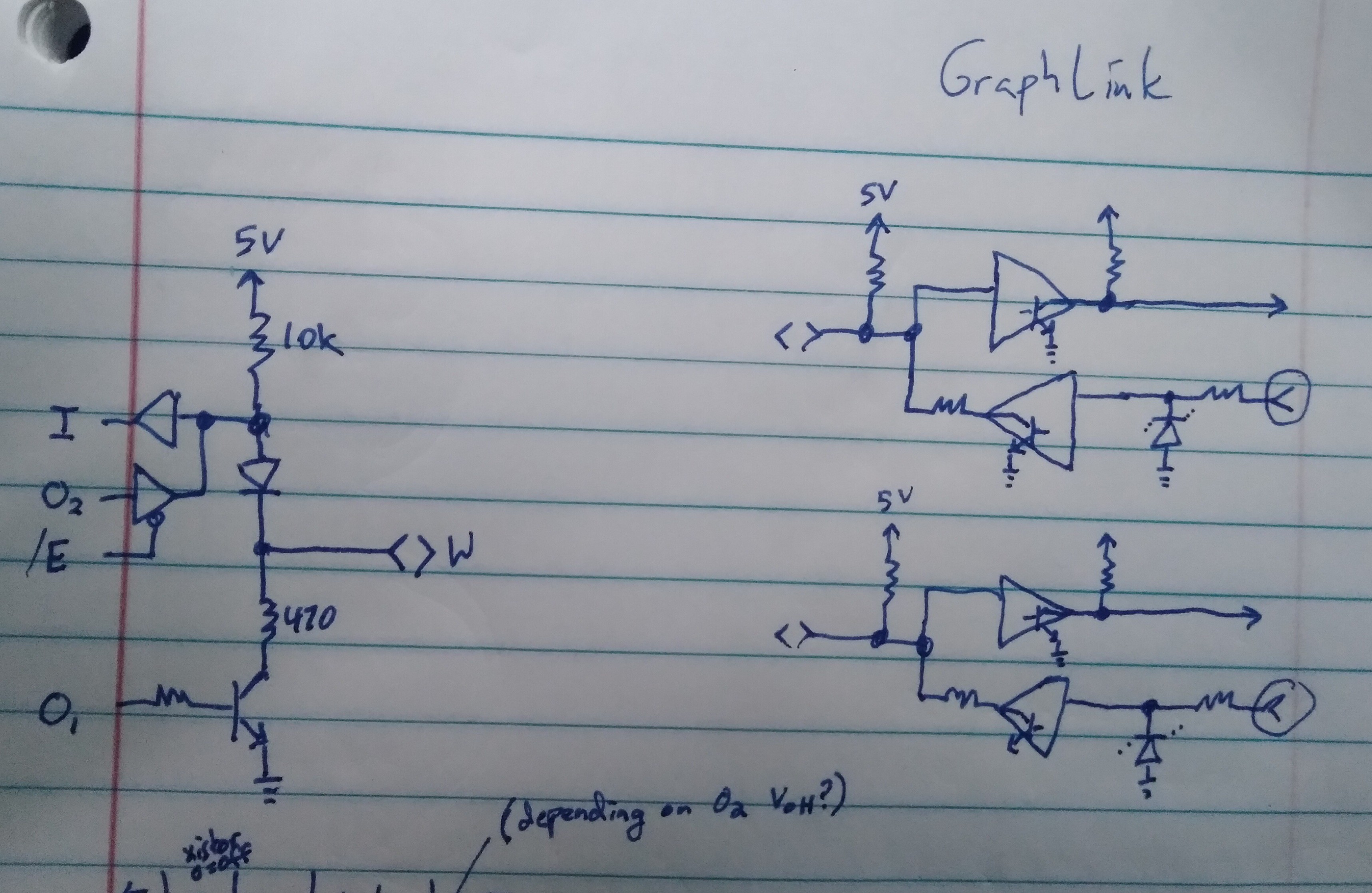
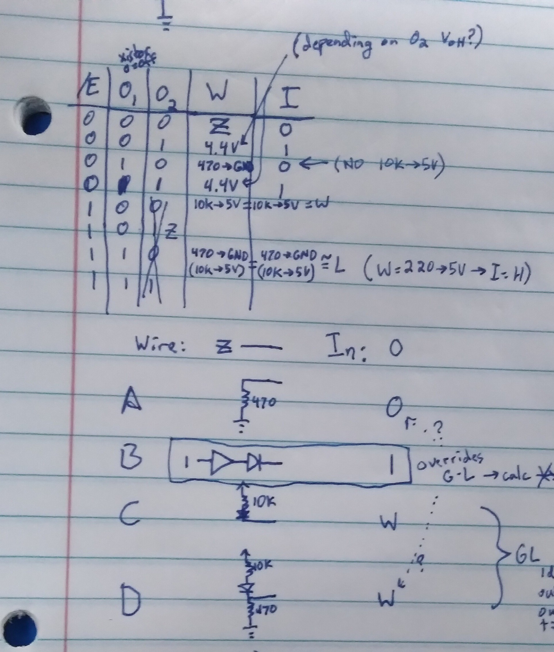
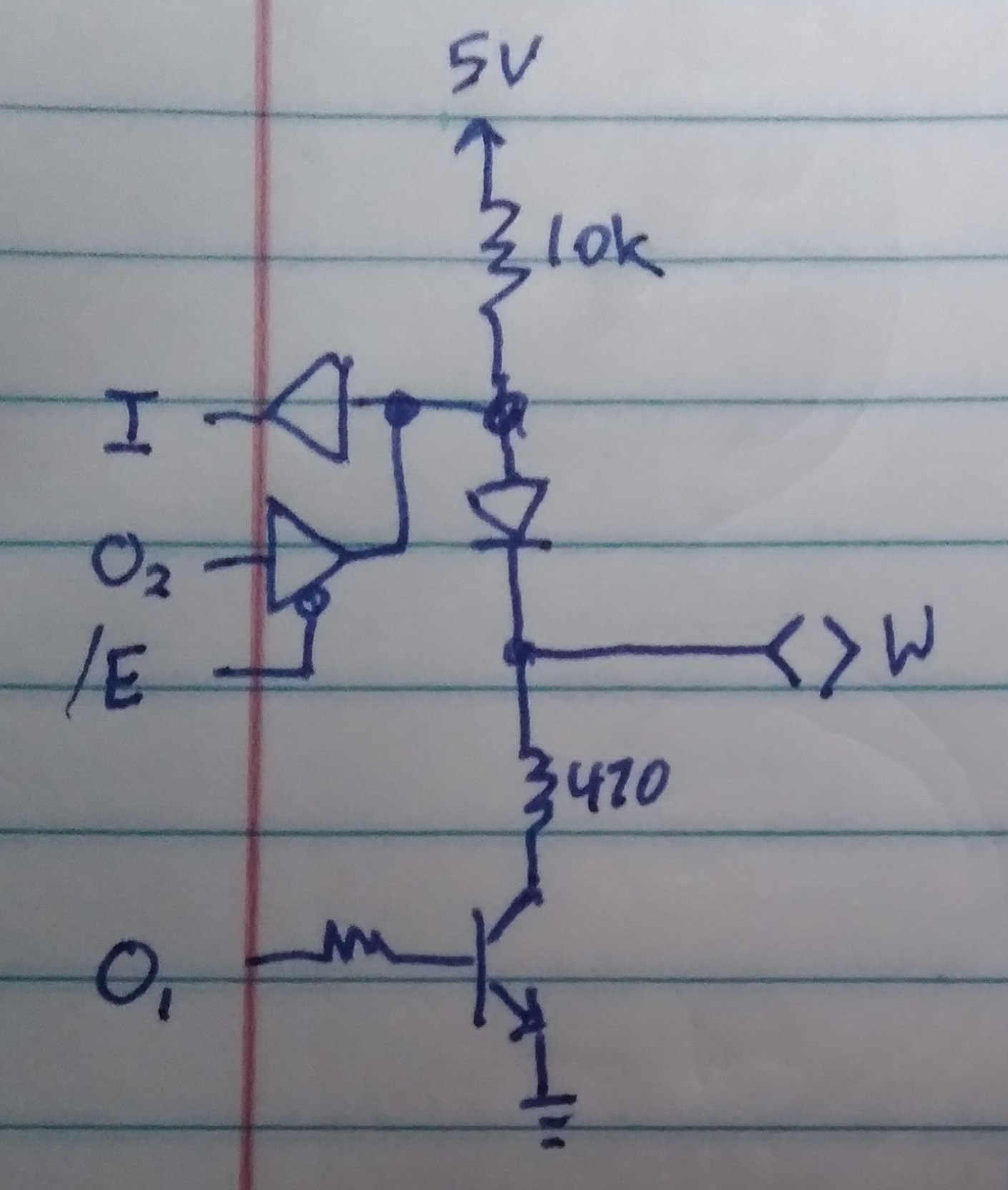
A:TI-86 Port 7 Info/Defines ;TI's Link-Port ;Note that TI-OS watches the ;link-port in _getkey(?) ;which is called in the ;200Hz interrupt(?). ;Best: ; 1 disable ints ; 2 dont connect custom ; harware until AFTER 1 ; 3 dont call OS-supplied ; keyboard funtions ; 4 disconnect custom hardware ; before 5 ; 5 restore Port 7 to TI-OS's ; idle state ; (call PORT7_restore) ; 6 reenable interrupts ;Port 7 : ;Internal: ;CPU I/O : 6V ;Buffers : | ; vv : $ 10K Resistor ;ID-<|-+------+ ;OD-|>-' : V Diode ;OED-' : +------->< wire ; : $ 470 Resistor ;OT-|>-+--~-|< NPN Transistor ;OET-' | : | ;IT-<|-' : GND ; Redrawn ;6V--~--+-|>|---+----->< wire ; 10K | pL,Z}| 470 ;..... |{H,L,Z '---~----. ;CPU :..|.......... b | c ; ID-<|-+ IT-<|-+--~--|< NPN ; OD-|>-' OT-|>-': | e ; OED-' OET-' : GND ;Through Diode: ; ID = Input Buffer ; OD = Output Buffer ; OED = Output Enable for ; Buffer to Diode ;Through Transistor: ; OT = Output to Transistor ; OET = Output Enable for ; Buffer to Transistor ; (almost always ON=1) ; IT = Input Buffer ("from ; Transistor" base) ; OET OED OT OD Wire ID ; v---unknown effect------- ; 0 0 X X pu? pu? ; 0 1 X 0 Z? 0 ; 0 1 X 1 H 1 ; ^---unknown effect------- ; best avoid "floating" base ;.--used by TI-OS for linking ;V ; OET OED OT OD Wire ID ;H 1 0 0 X pH pH ; 1 0 1 X vL vL ; 1 1 0 0 hZ 0 ; 1 1 0 1 dH 1* ;L 1 1 1 0 pL 0 ;* UNKNOWN if CPU output has ; the high drive-strength to ; overcome 470ohms to GND ; --------V--V------------- ; 1 1 1 1 H? 1* ; --------^--^------------- ; prb best to avoid competing ; drivers, though CPU driving ; high through 470 to GND may ; be OK, plausibly useful ;pL == pulled-Low through ; transistor/resistor. ; 6V/ID/OD/10K-pull-up ; effectively isolated ; from wire via reverse ; diode (see hZ note) ; 470 ; ~= GND --~-->< wire ; BUT: ID=0!!! ; ; pL is TI-OS's Link Low. ; Effectively output-only. ; Despite resistor, pulling ; the wire high externally ; will not be measured. ; For that, see vL. ;pH == pulled-High ; through diode: ; 6V --~---+-|>|-->< wire ; ID --<|--' ; 10K ; ~= 6V --~-->< ID=wire ; ; pH is TI-OS's Link Idle. ; Bidirectional. ; Wire/ID Reads High unless ; other device pulls low ; This MIGHT also work with ; similar bidir pulled-up ; open-collector interfaces ; such as i2c. ; However beware 6V! ; Ironically, this MIGHT work ; well with HIGHER-voltage ; OC/PU interfaces, since ; diode should prevent e.g. ; 12V from reaching CPU. ; Am presently working on ; such and cant quite ; convince myself to risk it ;dH == Driven High* from ; CPU Output via Diode ; OD=1 ---|>--+--|>|-->< wire ; ID=1 ---<|--' ; depending on connected ; circuit, may override ; circuit's pulling wire low ; E.g. another TI-86 could ; activate its low-pulling ; transistor (see vL), yet ; read the wire as high* ;hZ == High-Impedance via ; Reverse Output Diode: ; OD=0 --|>--+--|>|-->< wire ; ID=0 --<|--' ; note diode orientation ; effectively isolates ; wire and ID ; OD=0 --|>--+-- -->< wire ; ID=0 --<|--' ; May be useful e.g. with ; multiple devices on a bus ; OR to 3V3 logic input w/ ; external pull-up resistor ;vL == pulled-Low through ; Voltage-Divider: ; 10K 470 ; 6V --~---+-|>|-+--~-- GND ; ID --<|--' '-->< wire ; 470 ; ~= 0.3V --~-->< ID=wire ; ; vL Can Be Useful ; e.g. external 3V3 logic ; outputs to TI-86 ; :logic output : ; : __|__ __|__ : ; 3V3_:__7 \_._/ \,_:_GND ; :..PNP.|.NPN..: ; | ; 10K | 470 ; 6V --~--+-|>|-+--~---- GND ; ID --<|-' ; NOTE: Logic MUST Drive 8mA ; (Also CPU In=High Threshold ; Voltage unknown/untested) ; other I/O configs wont work ; pH: puts 6V INTO 3V3 output ; Can be bad when Logic=H ; dH: ditto worse, also ID=1 ; pL: ID=0 regardless of wire ; hZ: ditto ;port 7 (READ): ; TODO: VERIFY ;Bits 7-4 read-back config bit ; bit 7: =OET white wire ; bit 6: =OET red wire ; bit 5: =OED white ; bit 4: =OED red ;Bits 3,2 *usually* will, too ; bit 3: IT~=OT white ; bit 2: IT~=OT red ;Bits 1,0 read the "inputs" ;Though may differ per config ; bit 1: ID ~=white wire ; bit 0: ID ~=red wire ;port 7 (WRITE/Configure): ;.-bit 7: OET white wire ;|-bit 6: OET red wire ;|-bit 5: OED white ;|-bit 4: OED red ;|-bit 3: OT white ;|-bit 2: OT red ;|-bit 1: OD white ;|-bit 0: OD red ;| ;| "DIR"/OE OUT(VAL) ;| 7 6 5 4 3 2 1 0 port bit ;| 4 3 2 1 4 3 2 1 port pin ;'> T T D D T T D D ; w r w r w r w r wht/red ;TI-OS/linking uses: ;C0 1 1 0 0 0 0 X X pH pH ;D4 1 1 0 1 0 1 X 0 pH pL ;E8 1 1 1 0 1 0 0 X pL pH ;and rarely (on link error?): ;FC 1 1 1 1 1 1 0 0 pL pL PORT7_WpH_RpH =$C0 PORT7_WpH_RpL =$D4 PORT7_WpL_RpH =$E8 PORT7_WpL_RpL =$FC ;pL: input=0, wire pulled low ;pH: input=wire, pulled high ;vL: input=wire ~= pulled low ;dH: input=1, wire driven high ;hZ: input=0, wire high-Z PORT7_W_MASK =%10101010 PORT7_WpL =%10101000 PORT7_WpH =%10000000 PORT7_WvL =%10001000 PORT7_WdH =%10100010 PORT7_WhZ =%10100000 PORT7_R_MASK =%01010101 PORT7_RpL =%01010100 PORT7_RpH =%01000000 PORT7_RvL =%01000100 PORT7_RdH =%01010001 PORT7_RhZ =%01010000 ;NOTE: PORT READ does NOT ; match last PORT WRITE ; (in lowest four bits) ;THUS: can NOT simply ; read/modify/write ;ALSO: can NOT simply read ; port 7 at program entry ; then restore that value ; before returning to TI-OS. ;THUS CALL PORT7_restore, ; or USE PORT7_TIOS_IDLE, ; AND THEN reenable interrupts ; before exit PORT7_TIOS_IDLE =PORT7_WpH_RpH ;restore port 7 for TI-OS ; Dont forget to re-enable ; interrupts, thereafter PORT7_restore: ld a,PORT7_TIOS_IDLE out (7),a ret ;E.G. Custom for 3V3-serial: ; wht red ; Rx Tx ;C8 1 1 0 0 1 0 X X vL pH ;DC 1 1 0 1 1 1 X 0 vL pL PORT7_WvL_RpH =$C8 PORT7_WvL_RpL =$DC ;wh=input=vL prevents 6V from ; feeding into 3V3 output. ; Output must drive 8ma! ;red=output=pH ONLY SAFE HERE ; because My converter has ; a zener at Rx ; (OTW maybe use hZ ; AND add pull-up to 3V3) ;Then in iUART3V3: ; TxLOW =PORT7_WvL_RpL ; TxHIGH =PORT7_WvL_RpH -
Fail: Higher than measurement accuracy through math?
10/02/2021 at 21:24 • 0 commentsI'm really quite rusty on percentages, so this is /likely/ a math-error on my part...
But, here's the quick of it:
I'm measuring the number of events in a time-period... the error could be +-1 time-unit and/or +-1 event.
With my current numbers, this gives a worst-case error of +2.5% to -2.4%.
Now: if i do dimensional-analysis via integer-math to convert from events/its-time-units to events/human-readable units, I'm calculating worst-cases of +2.5% to -1.9% error.
The measurement-error /decreased/?!
Can that possibly be?
.....
Here's the setup:
49 clock pulses are measured in 263 samples. Say either or both could have a measurement error of +-1.
Samples occur once per 21 CPU cycles.
The clock pulses occur at 41666.66666 clocks/sec
Now I want to calculate the cpu frequency.
263(Samples)/49(clk) * 21(CPUclk)/1(Sample)
* 41667(clk)/1(sec) = 4.6965M (CPUclk/sec)
....
Because I'm doing this via 8bit z80 assembly, I'm limiting this to 16bit x 8bit multiplication and division.
The tricks, there, involve recognizing some facts about the exact constants involved...
21*41666.66666 is exactly 875,000
No measurement error, here... (Though, of course, it presumes the clock is exactly 41666.666666Hz, but, I guess we'll set /that/ as our anchor for these error calculations).
OK, I can deal with KHz for the CPU clk... so, can divide 875,000 to 875.
But, 263*875 can't be done with my 16x8 multiplier. So, note that 875 is exactly 175*5.
Then 263*175 fits in 16x8 mult...
Giving 46025
Now, that's too large for any additional multiplication, so let's do the division...
46025/49=939.29... but, of course, this is integer math, no rounding, giving 939,
Now, I'm a bit worried that .29 adds to the error, but we'll come back to that.
We still need to multiply by 5...
939*5=4,695KHz
Earlier, in floating-point, I calculated
4,696.5KHz
Not bad for integer-math, no rounding... but was I just lucky with these numbers?
....
So, obviously, the two numbers differ, and obviously /that/ error came (mostly?) from my integer-math. Of course dropping decimal places is going to introduce error. My concern is /how much/?
Let's start with the potential measurement-error.
263/49 = 5.367
Worst-cases occur when each measurement is off by 1 in opposite directions:
264/48=5.5, 102.47%, +2.5%
262/50=5.24, 97.63% -2.4%
...
Now here's me going through it step-by-step... again, it's entirely likely I'm wrong...
263*175: whatever error was in 263 has now been multiplied by 175... 263 was +-1, so 263+175 is +-175. Sounds awful... but it's 175 in 46025, so less than 1%. And since 175 is exact, it should be exactly the same percentage-error as for 263.
Next step is divide by 49. 46205/49. We've got +-175 error up top, +-1 error on the bottom... I dunno how to math percentages like that... instead we'll look again at worst-case: divide by a smaller number gives a bigger number... So, 48... put that at the bottom of 175... the result of 46025/49=939.29 is off by 175/48, worst-case... in either direction. +-3.646. But, this is integer math, not rounded... 939. And rounding down the decimal place could result in an error of up to -0.999999=-1. So our +-3.646 error becomes -4.646 to +3.646 in 939.29... looks tiny, but the math is not complete. 939 gets multiplied by 5, and so does that error...
.....
Fail.
Yeah, I wrote that up after calculating it on paper... and after going over the paper calcs several times...
This fail has been days in the making.
No... if it's 48, then it's not off by 175/48, but off by 46025/49 - (46025 + 175)/48, which is dang-near spot-on the original +2.5%, right?
Gah! Don't think that's right either...
Forget this... I dunno what I'm doing, here.
I am, however, pretty sure my *875 trickery shouldn't introduce nearly as much error as the measurements themselves., and should get the job done.
Tangent abandoned... if brain allows.
...
It doesn't.
Ok, here's the deal, yes: I think the error /range/ decreases, but the probability distribution (i made that up, yeah?) changes, too... it's more likely to be in more error than it was, but it can't be in as much error. Or something. And somehow that's caused by the lobbing off of the decimal... the greatest error comes when one measurement is off in one direction, and the other is off in the other direction... but, realistically, that can't happen (right?), because both measurements (time and sample) happen simultaneously, inherently.
So somewhere therein, the reality of the situation is that /both/ measurements /inherently/ are integers, and fractional differences between them /can't/ exist, so therefore, inherently, if done properly, the math /using/ integers is more accurate than that using floating point... OR SOMETHING. Heh.
And the /potential/ error-range has to take that into account, too...
It can't be off by 1, but it can be off by 0.9999... and that difference actually matters. If you're going to try to figure out this crazy endeavor.
I'm lost. Somewhere in there it all makes sense.
I need to get this stupid thing functioning, for my sanity. Teeny tiny error be dammed. Heh.
-
How rugged is that TI-86 link port, anyhow?
09/29/2021 at 00:39 • 0 comments...yyyyyyyeeeeaaaahhhh....
I Had somewhere in all this mess forgotten the link-port's limitations.
I need one input and one bidirectional.
Two wires, right?
OK, but, my bidirectional signal is open-collector and pulled up to 7V, possibly 12V, at the device-side.
I'd been planning to use the graphlink->DB-9 adapter as a level-shifter... but this creates a problem. If I wire the graphlink's output to the same linkport-wire's input circuit, then we create a latch. When the device sends a low, the graphlink latches it.
![]()
I thought maybe I could use the two separate linkport wires for input and output for my bidir signal, then the one used as an output there could be multiplexed for the other signal's input... but, the wiring of the graphlink and linkport would feed that signal back out to the bidirectional wire. No good.
OK... so, The way the linkport works, it /is/ possible to drive the wires with a real-ish "high" rather than the usual pulled-up... that could be used to unlatch the low latching...
![]()
If I throw that in my bit-sampling delay-loop, I think it'd make my loop 44T-States, which is around about 9us... At 10.4kbits/sec, that's at-worst about 10% of a bit-duration, and usually one would sample a bit at about 50% anyhow.
So, as far as a typical uart signal goes, this'd probably work.
OTOH, I don't have a lot of info about this bidirectional-one-wire UART... it's entirely plausible (as in most bidirectional one wire serial systems?) that the device watches the wire to see if it's following what it's sending, and if not, then it gives up the wire to what it thinks is another device talking.
Dunno, here. So, with this setup/idea, its low bits will be extended by ~9us... which could be a problem.
I could plausibly speed that up a bit by going back to sampling, and post-processing, but, still, it'd extend those low bits several us.
.....
An alternative is to wire both signals /directly/ to the calc's link port... all 12V of it.
And, actually, it almost looks like that'd be acceptable. But I really don't like that idea.
But... I mean... Why not? It's all well separated from the CPU... diode-protected...
![]()
Hmmm...
....
I'm also feeling exceptionally overwhelmed with what all's necessary to put all my code together. I've got the clock-sampling, but presently it loads that to a screenshot. I've got the clock-rate calculator, but that takes it from a screenshot. Merging those and removing the screenshot bit /should/ be easy, but that never seems to work out that way.
From there, I need to calculate the bit durations, and I've already figured that out... per last log's ramblings, friggin NumSamples*84/NumClocks.
Ahhh, right. Still need to write that division function. Easy-peasy, right?
Multiplication I thought was done days ago, turns out it was buggy. Fixed.
Then, feed that to my T-State delay function (which may need to be modified to unlatch the input).
Then stick that in the UART bitbanging code. Both transmit and receive.
Then... protocol... which is allegedly documented, and yet every doc seems different.
And, again, this system is request/respond, so if my request isn't right, who knows even /if/ I'll get a response.
Why do I feel so daunted by all this /now/?! Coulda gone through that weeks ago, before all this work.
...
Ahh, yes... AND, I'd been planning some testing via a computer's UART... 9600baud. But... hmm... that too is quite daunting. First-off, simulating my clock-source... I suppose I could send a burst of 10 0x55's from Compy, that'd pretty much match the 49 clocks from the other system. But, I should probably try it at a higher rate than the 9600... but, of course, every RS-232 bit rate is an integer multiple of the others, so its not a /great/ test. And, Of course, it's not single-wire, nor open-collector, so this "simple" test is starting to become a bit of an ordeal. Especially considering testing the delatcher...
...
Gah! The delatcher has to delatch at the /edge/ of the bit, but I'd rather sample near the middle! That means two separate delays per bit?
No... wait... I thought about this, didn't I? No, the delatcher works as long as we're in the delay loop. OTOH, the delay loop only runs for about 30%(less?) of the total delay between bits, the rest of the delay time is occupied by setup for the delay, shifting-in the bit, storing the byte, etc. hmm, this could be iffy. So ideally the delay loop starts just before the bit edge, then completes near the middle... hmm.
This project is /really/ pushing Calcy's limits. Heh. And mine... i've lost so much steam these past few days.
...
Division function complete. Also started breaking the big pwm/clock-sample-parser program into pieces for inclusion elsewhere... then it hit:
Save tPrsPWMS -> bPPWMS2
"ERROR: MEMORY"
as I recall, it didn't even say memory-full... just "Memory". Like it would've used up RAM to store the word "Full" in the ROM? Heh.
OK, first: kinda funny I /just/ mentioned pushing poor Calcy's limits... then hitting one.
Second: WOOHOO! This is a big moment!
Think about thumbtyping 92KB of assembly on a 30x8 character display! Ok... well, that includes a few backups (remember, though, I just sorted through those and removed them /all/ a few days ago) and also a few KB for ZAC and Asmide86, oh also 3KB for screenshots... Oh, and the compiled executables, themselves... OK, maybe I've thumbtyped half that, still 46KB ain't nothin to scoff at!
...
FYI BAD IDEA to use ZAC/Asmide86 when the memory is nearing the limit....
Open File, typed-up some changes, save, "memory", "whattya complaining about, it says I've got 2K free!" gone.
I mean, it's not good practice, anyhow...
Have not at all been in the mood to hook up the computer to backup...
And, actually, shoot... i mean, I'll have to unload some stuff. Hah!
Didn't I add FLASH for just this sort of thing?
Still... gotta code up the transfer utility... and that means I needta make space for coding. Heh!
-
Dimensional analysis fails me again
09/26/2021 at 21:04 • 0 commentsI never seem to get it right. It makes /so much/ sense, and yet completely eludes me whenever i try to apply it in even the tiniest way outside the norm.
In fact, now I'm at a complete loss for how ft-lb or A-hr work.
So, I can't really explain how this works, but I'm near certain it does...
I measure 49 clock pulses, coming in at 41.667k/s in 263 loops... then want to find out how many delay loops I need to create a UART bitrate at 10.4kbps.
One loop is 21 T-states (CPU clock cycles), though I've found that to be irrelevant, because I managed to make both the measurement loop and the delay loop exactly the same length.
Now, 41.667/10.4 happens to be almost exactly 4. But, later I might like to reuse this with 9600baud, or maybe a different clock. 41667/9600 is... 4. Unless you're using floating-point. And I'm definitely not about to handcode floating-point. So, I can't just multiply the measured loop-count by 4...
So, back to our measurements:
To convert an arbitrary measurement of loops and clocks to a number of loops per an arbitrary bit-rate:
( A[loops] / B[clocks] ) * ( C[clocks/sec] / D[bits/sec] ) = ((A * C) / (B * D)) [loops/bit]
Sounds about right... our C/D = 4.006, so 4 should be fine, but not if I want 9600bps.
So I multiply C and D for higher precision...
I'd prefer to use 16bit math, since that's in the z80 defacto. So, turns out 125[clk/sec] / 31[b/sec] = 4.03 is closer, anyhow, and 125/29 is pretty good for 9600.
(Why didn't I go with 128? Some random prof-of-concept math got me there, I might actually change it to 256, and stop sampling at 256 samples, so the top number (A*C) is always 65536 which would make later math/comparisons easier)
So, now, it starts getting confusing...
Each loop takes 21 T-States. Why is this important, here? It's the same for sampling... forget T-states. Erm...
OK, so, the problem is, I'm trying to relate this to /units/, and I can't.
So each loop is essentially one subtraction in the process of division.
The denominator (B*D) gets added each loop, until it reaches the numerator. When it does, we've delayed the right amount to toggle the next UART bit.
So, lemme give a simple example: we know that it should quit delaying after four loops, right? No, because it's 263loops/49clks. Oy, let's round... 250/50->25/5->5/1... five loops per clock, say. And 4 clocks per bit... so 20 loops per bit.
OK.
Now, 20/1=0 in the first loop, 20/2=0 in the second loop... 20/19=0 in the 19th loop, then finally 20/20=1 is therefore the final loop...
Division, but using addition, instead.
OK, so if I'da done that with real numbers,
( A[loops] / B[clocks] ) * ( C[clocks/sec] / D[bits/sec] ) = ((A * C) / (B * D)) [loops/bit]
A=263 loops per...
B=49 clocks.
C=125 clocks per...
D=31 bits.
A*C=32875 [loop*clocks] (?!)
B*D=1519 [clock*bits] (?!)
And if I do the math, then for a few loops:
Loop1: 1519 < 32875, so continue
Loop2: 3038 < 32875
Loop3: 4557...
Loop21: 31899 < 32875, so continue
Loop22: 33418 > 32875, so stop
So, it overshot a bit, (no more than one loop, or 21 T-States, or roughly 4.5us at 4.7MHz) but that's nowhere near one bit duration of 96us, and I can account for the overshoot in the next bit's delay, such that overall the error doesn't add up.
So, i think you can see that if i changed my scale-factor (clks/bits) such that the numerator is 65536, then I don't have to compare two 16bit numbers, and can instead just keep adding to the 16bit numerator until it overflows from 64000ish to 0-1000ish, which, during that last addition, causes the "carry" flag to be set, telling it to stop looping/delaying, /and/ prepares the next delay to compensate for this one's overshoot.
OK, but now,what the heck are we counting, here? I mean, units-wise...
( A[loops] / B[clocks] ) * ( C[clocks/sec] / D[bits/sec] ) = ((A * C) / (B * D)) [loops/bit]
A=263 loops per...
B=49 clocks.
C=125 clocks per...
D=31 bits.
A*C=32875 [loop*clocks] (?!)
B*D=1519 [clock*bits] (?!)
What the heck does it mean "how many clock-bits are there in a loop-clock?"
I have no friggin clue. What the heck is a clock*bit? Or a loop*clock? Or, for that matter, a foot-pound or an Amp-hour? And, frankly, now I'm at a near complete loss. OK, Amp-hours in a battery are per battery recharge. So, realistically, the units of "Amp-hours" are equal to "Recharges?" And foot-pounds... well, now it's starting to seem a bit like the x*y units equate to some sort of unit meaning something like "available".
4Ah/1Available=1, then 4Ah=1Available, then 4A=1Available/hr... ?i dunno, I'm lost again. And, here, I'd been planning to use dimensional analysis to figure out /whether/ my algorithm is sound, /and/ to figure out the next hurdle, which is:
There are /other/ things going-on between my delay-loops... I've got to extract the next bit from the byte,then output that to the port. I've got to /call/ the delay function, and return from it... So, that means, I need to subtract those calculations'/instructions' times from my delay... but how do i convert from T-States to clock-bits?!
Best I can figure is that I know X clock-bits is one 21T-State loop. So, if there are, say, 190 T-States of calculations inbetween my last delay loop and this one, then I need to divide 190/21 then multiply that by X clock-bits, again, whatever the heck those are.
I'm pretty certain this'll work, and I did come up with it, but I just can't quite wrap my head around it.
...
Holy crud, I'd been working on this for days... i just about got it, except for having to calculate the number of Loops from the number of intermediate T-states, then converting it to clk-bits... which would take well into the hundreds of T-states with a multiplication and division.
So then the thought to just require X t-states between calls (throw in some NOPS) so that could be precalculated, but no, it can't, the whole point is that our T-states are of a /measured/ rate, thus needs to be calculated based on measurements... then the thought of having a delay_setup() function that does that calc once before actually calling the delays.... (Why'd I stop there, it woulda worked!)
But I stepped back, /finally/...
263 [Loops] * 21 [T-States/Loop] * 41.67 [kclks/sec]
----------------------------------------------------
49 [clks] * 10.4 [kbits/sec]
==== [ T-States / bit ]
And everything except 263 and 49 are constant....
21*41.67/10.4 = 84.14
9.6Kbps? 91.15
Rounding gives 84 and 91, each with way under 1% error.
Now it's simply: 263 * 84 / 49.
If I'm /really/ smart I might limit the samples to 256, then it's all 8-bit math. Wait, no... that aint right. Anyhow, I already wrote my uint8 * uint16 function. And the clock bursts are too short to make loops*84 overflow a uint16... (right?) So I'm all set.
The answer gives T-States per UART bit... with these numbers, 450 and 489 for 10.4k and 9.6k.
I already wrote my T-State delay function. DAYS AGO.
SHEESH.
....
AAAAHHHHH
BUT....
Using the earlier logic, I CAN do this /without/ an explicit division.
Count up to 263*84=22092
In steps of 49
Instead of counting to 450 T-States in steps of 21 T-States per loop.
Right?
...
LOL multiple fail, again.
First-off: 263 * 84 / 49 gives T-States/bit, 450 of them.
Which is great. But if I do the divide-by-49 in the delay loop [repeatedly adding 49 until it reaches 263*84] then I get 450 /loops/, each of which is 21 T-States.
So, no, I need to repeatedly add 49*21, which gives 21 loops. OK, no problem. And, that happens to make my math WAY easier when calculating how many loops to subtract due to intermediate T-States used for setup calculations, call/return, and toggling the Tx line... say the call/setup overhead is 190 T-States, then I just multiply 190*49 and start the loops from there, successively adding 21*49 to that, thereafter. WAY easier, I thought I'd have to divide 190/49!
Still, I need an 8-bit times 16-bit multiplier, and I need it to take fewer than 450-190 T-States, and I need it to take a constant number of T-States, regardless of the input values. Presently, I think mine's around 400 T-States. Heh.
So, 21*49 is pretty doable, first-off it only has to be done once, maybe even before even beginning UART stuff at all. Secondly, 21 is constant, so it could be as simple as A<<4 + A<<2 + A.
The call/setup overhead is also constant, 190T, presently, which could be done similarly, but also similarly could be calculated once before even doing the first delay.
That leaves the intermediate T-States (which also have to be removed from the number of delay loops) used for setting up the data on the wire, etc. This varies... E.G. grabbing the byte from the buffer, after the UART Start-Bit, then merely shifting it between each bit-delay thereafter. So, when I was convinced there was going to be a division involved, I decided maybe to just allocate a fixed number of inbetween-call T-states, and expect the caller to pad with NOPs as necessary. Then, those'd just be grouped with the 190 overhead t-states.
Now, it seems, it's not a division, but a multiplication... hmmm... which can be much faster... hmm...
Another trick I thought of was to just require the caller to use an integer-multiple of 21T-states in the intermediary between delay calls. Though, now that number still needs to be multiplied by a variable [49, this time] in the overhead between each call.
Oh, and, BTW, shift-left in z80 assembly only occurs one shift at a time... don't let C's "A<<4" operator fool you into believing that's a single shift-instruction, heh! In fact, since shifts don't exist for 16-bit registers, I read the trick is simply to add hl,hl to do a single left-shift. Which is kinda backstepping for me, having learned so many tricks (like shifting to multiply) that I'd almost forgot multiplication is repeated addition, heh!
Anyhow, where was I?
Oh, so that big moment where I realized I could simply add 49 until it reached 263*84 (forgetting, of course, that I needed to multiply 49*21 first), I had completely forgotten how much overhead doing-so would add to the setup/call/intermediate T-State calculations... which is pretty stupid, considering that's /exactly/ what I'd been wracking my brain over for days prior, and even just 20min prior. Heh.
OK, BUT, this time I think I've got it... subtract, from 263*84, the intermediate T-States * 49. Intermediate T-states could be forced into some amount of conformity with NOPs, the math could be done in one delay_setup() call before any/all delays, and could even be /really/ slow.
Am I missing anything?
.....
I did something like this on my AVR-based raster-scanned-LCD controller... a delay used to display "row-segments" of varying lengths, with a minimum length due to calculation overhead, but which could ultimately be delayed precisely down to a specific CPU clock cycle... HAH, imagine trying to do that with a machine whose shortest instruction is 4 CPU-Cycles, and most take far more... [BUT they're /not/ integer-multiples of 4, so I think it could be done!] Challenge begrudgingly not accepted. Though, it'll probably be hard to take off the stove.
Jitter, due to the 21T-State loop-length, should be more than acceptable, here, as long as it doesn't add-up... Which this system is designed to account for (subtract the last delay's overshoot from this delay).
So... do I have it?
Count to 263*84 in steps of 49*21
But, first, start the count at the last count's overshoot (conveniently already in whatever units 49[clks]*21[Tstates/loop] necessitate/mean)
Then add the overhead/intermediate T-States, times 49[clks], for some only vaguely-understood reason...
And only /Then/ start the counting-up, from there, to 263*84
...
There's a reason I'm doing all this, rather than merely delaying a specific number of T-States.
The error would add up/compound, otherwise.
The resolution would be quite small.
Floating point would be necessary.
Division is a /slow/ process. Especially if the algorithm has to handle any input values.
Division is /exactly/ what we /want/ to do, here, in its simplest form; keep subtracting until you can't anymore... that /is/ our delay.
...
Doing it with 49*21 per 21T-State loop allows for a higher resolution over the long-term...
If I'd've done the math in terms of /loops/, instead: well, 263*84=22092, /49=450.857
But, that's T-States, and we're not using floating-point, so now we've lost 0.8 T-states per delay. That, would be, if we counted each loop in steps of 21 (T-States) to 450.
Now, what if we counted in loops, instead?
450.857T/21[T/Loop]=21.469 loops...
Which'd be 21...
21 loops is 21*21T=441T, which is already more than 2% error, /per bit/. And, again, that error would compound.
That means, after 50 bits, or five bytes, we've managed to stuff in an extra bit. Somewhere that data is corrupt.
Say we did it with T-States, 450, rather'n 450.857, tiny error, right? But, 0.2% means we stuff an extra bit every 500bits, which is 50 bytes.
This system doesn't deal with large bursts, as far as I'm aware... I think I heard 13 bytes, maximum, so counting T-states /should/ be fine... but, there's plenty more to consider. What error was introduced in my measurement of the clock? 263loops/49clks sounds pretty good, right? But what if it was 263.999loops/49clks?
That's a 0.4% error which combined with our 0.2 above starts to add up... potentially near 1% again.
What if it was 263/49.999? That's a 2% error, right there, combined with our earlier seemingly-negligible 0.2 could add up quite a bit. I honestly don't recall how to do that math, but every bit can add up.
2% measurement error is quite a bit, could interfere with every 5 bytes. But there's really nothing I can do about that... but I can try to minimize the error's being compounded. And, who knows, maybe I'll figure out a way to increase the measurement accuracy. (The clocks come in bursts, of apparently 49, but I could maybe sample numerous such bursts and average...)
Alternatively, maybe, I can sample each bit twice, and if it's not measured the same then reset the delay overshoot to zero or something.
(I hadn't run those percentages, yet... 2%! Oof.)
/Transmitting/ isn't as much a problem, the transmit line of a UART /should/ be OK with an idle of any duration longer than a stop-bit. I could add two, or more. The receiver should be OK with that.
But, /receiving/... There's no guarantee the transmitter will add /any/ idle between bits. Just a stop-bit... which could mean that 130 bits come through back-to-back.
Now, ideally, I could reset my delays with the edge of each start-bit... 2% should only cause a problem after 50 bits, but if I reset every 10 bits then it should be OK. Will there be enough time, though, in thr 450.875 T-states, between the last bit in one byte and the start-bit in the next, to store the received byte AND do all that setup for the next?
Then there's the error introduced by the system watching for the start-bit edge... I dunno if I can keep that as low as 21T/loop, which means there's a 4us window where the start-bit may arrive... 4us in 96us/bit is well over 4% error... no biggy if everything's otherwise synced, that 4% doesn't compound, but still, could add up with the others.
So, ideally, I'll introduce as little extra error as possible.
And one way to do that is by counting my 21T-State loops in a different set of units, with a larger, more-precise, step-size. and counting up to a larger, more precise, value in whatever weird units I came up with. And keeping track of the overshoot, which may be as large as 4us (4% error!) for each bit, but in keeping track of that overshoot, subtracting it for the next bit.
I think it works.
...
*SIGH* WHY am I doing this, again? I already wrote a t-state delay routine that handles the jitter issue, etc.
Oh yeah... to calculate the number of T-States /to/ delay, I need division...
Oooof.
Because, I'm a bit stuck, again, trying to convert the intermediate T-States into these weird units.
16x8 multiplication, looks to be about 400T-States, which doesn't leave enough for the delay overhead. Right.
So, I've got to do some setup /before/ starting the delays, anyhow... but, my division, to calculate T-States... 263*84/49... nah, 16/8 (bits)... OK...
And the overall additive error...? Surely I can setup a new delay sequence with each start-bit... so the additive error would have to be nearly 10% per bit to really be a problem... right?
Sheesh.
I guess the main thing was trying to do the /49 in realtime, rather'n precalculating. I dunno. I definitely don't feel like writing a division routine.
T-State-delayer, pre-calculated division, go!
-
Calcy the rugged outdoorsman
09/22/2021 at 23:12 • 0 comments![]()
Apparently I convinced whoever's in charge of the rain that I was pretty serious about making some progress today, rain or shine.
Also, saw this on my way here...
![]()
Yup, that's a truck on a towtruck on a towtruck. And I think the crane that made it possible. I didn't have time to grab the camera for the police escort. This really made my day.
-
Calcy's great uncle, and project updates
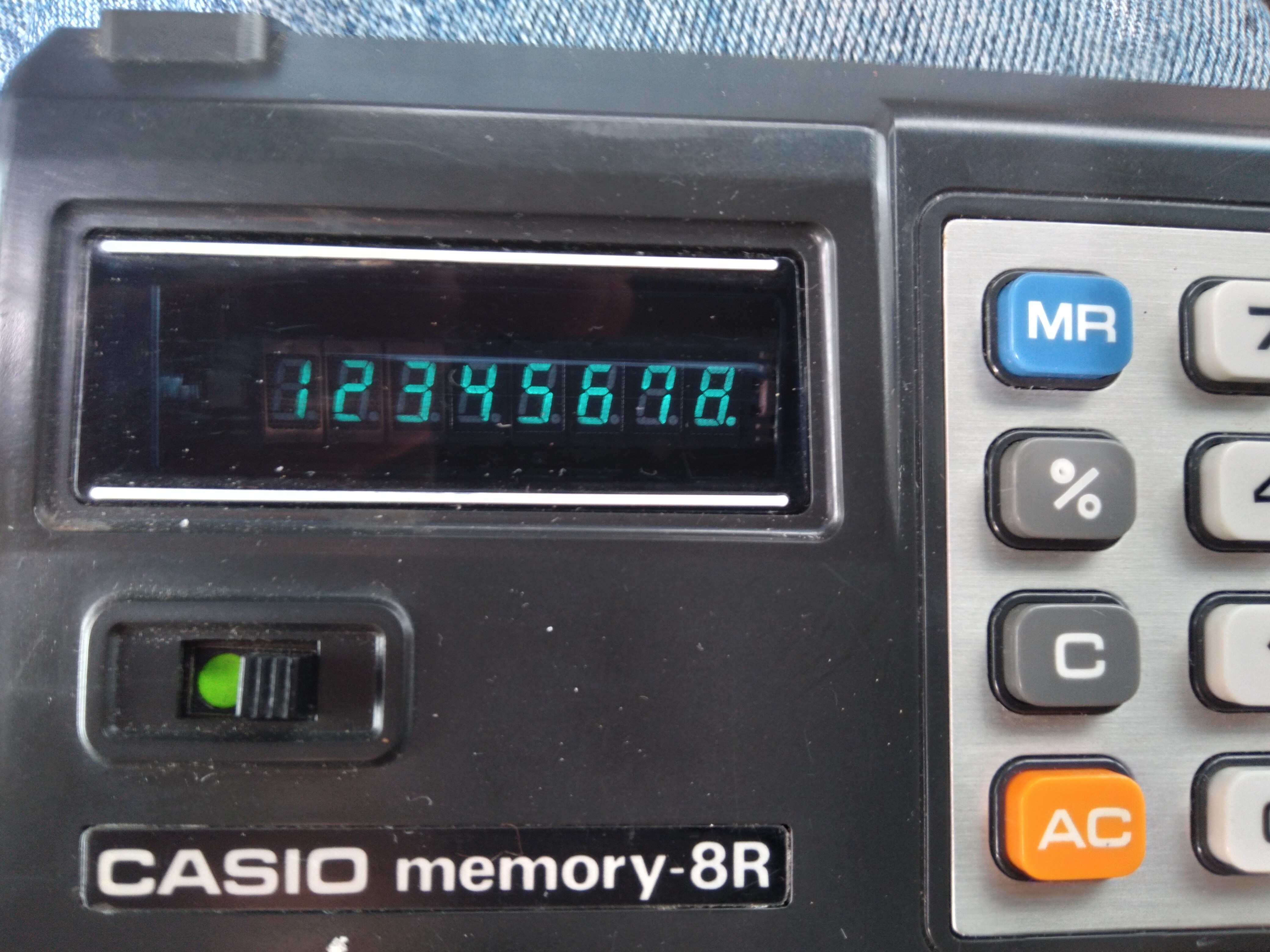
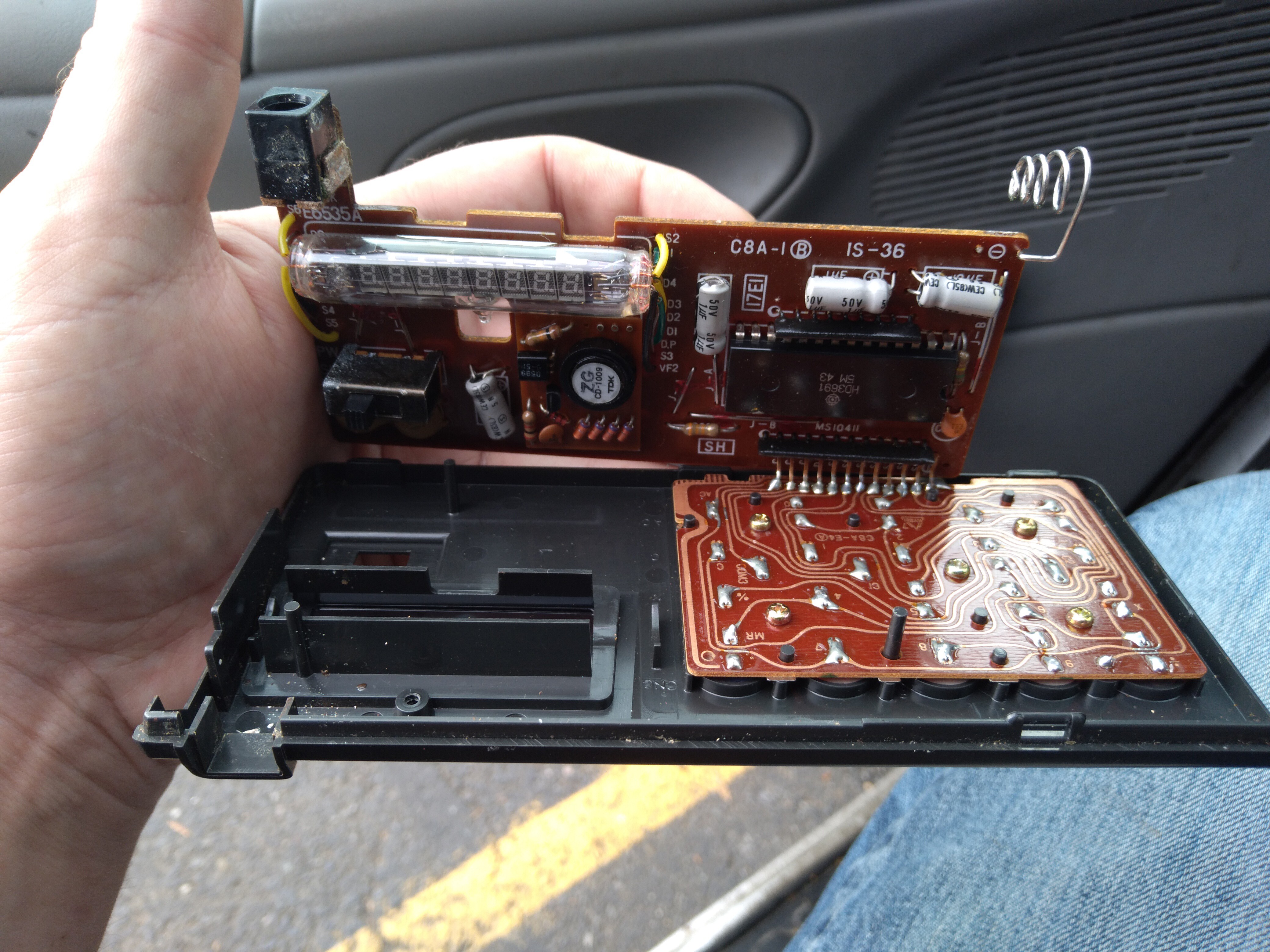
09/21/2021 at 01:54 • 9 commentslook at that wonderful VFD!
![]()
<s>Well, shoot, I took the batteries out, and they've since fallen well out of reach. You'll just have to take my word for it,</s> that's a nice little Vacuum Fluorescent Display. $2.99, how could I pass it up?!
![]()
Half of me wants to hack it into the TI-86 for some purpose... maybe displaying the z80's data/address bus? 8 digits is perfect... 24 address bits after the memory-mappers is 6 hex digits, two more for data... I had been contemplating single-stepping and toggle-switch inputs a while back...
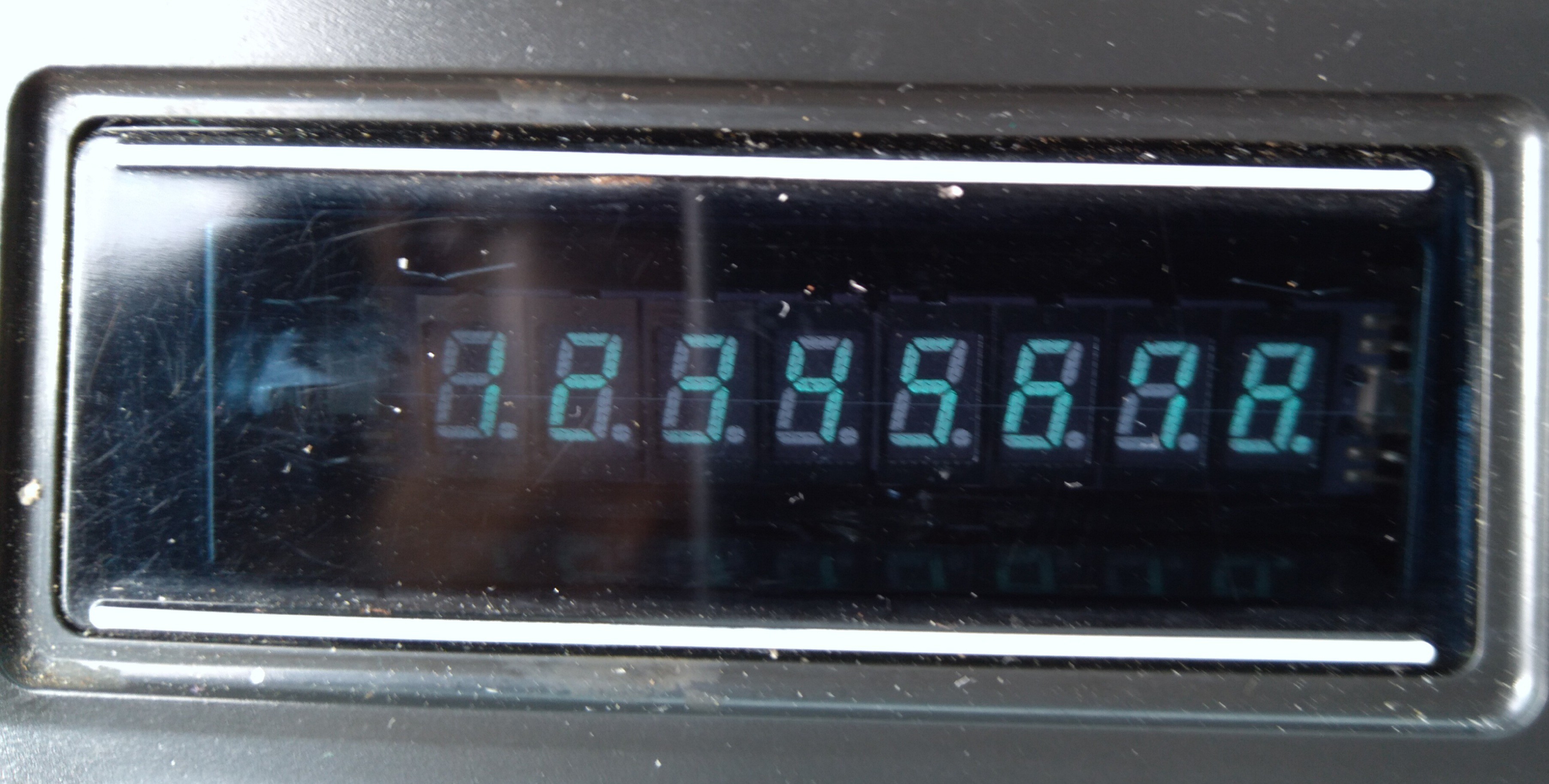
Initially, upon seeing this i thought each digit was a separate display, which I thought would be great for a wristwatch, and maybe various other projects. But, even weirder than those flat VFDs you find in VCRs and such, this guy is in a glass /tube/, cylindrical! How 'bout that?
You can almost make it out, here. Interestingly, both ends have wires coming out, unlike most tubes.
![]()
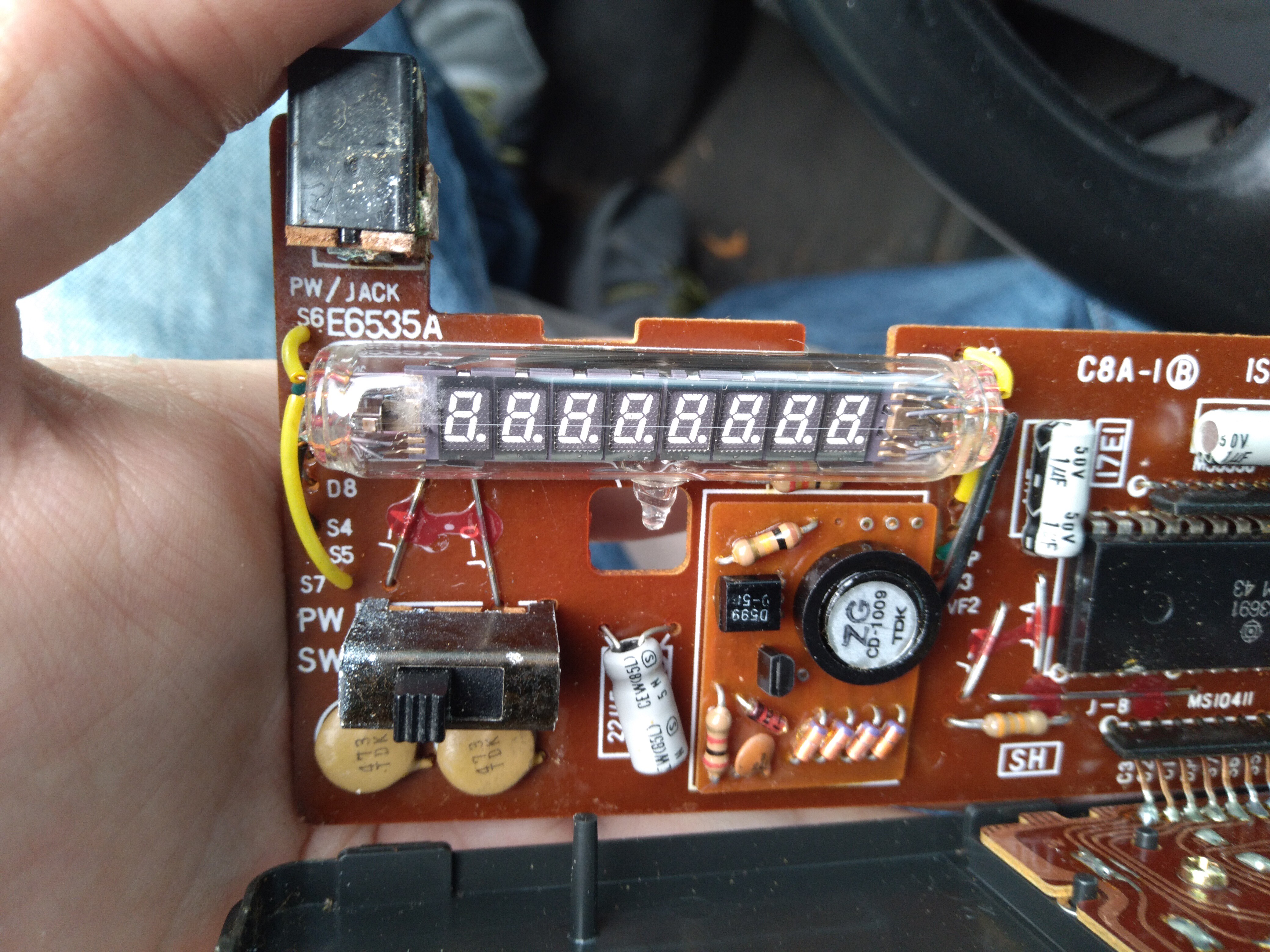
... oh heck, I've already gone this far, and I left the lone screw out since it still snaps together quite nicely at some 50 years(?!) old.
![]()
![]()
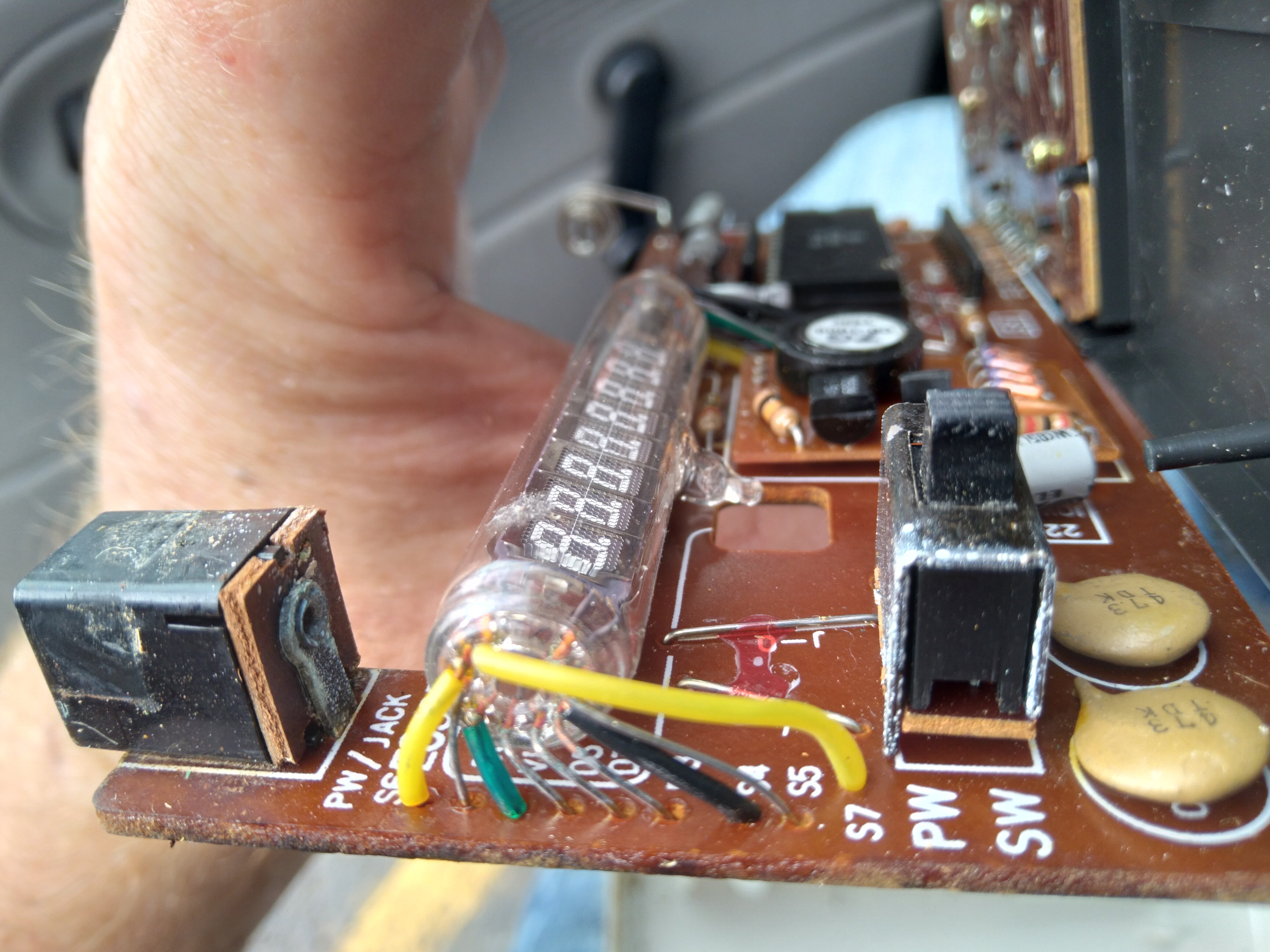
I dig that the leads are spiralled out from the circular layout.
![]()
Bad shot, sorry... but there's really not much in there, and what is is mostly repairable/replaceable/hackable... I dig that, too. Probably part of the reason it's still around after fifty years.
Also, oddly, I noticed no friggin' datecodes! Best I found was maybe "45", but obviously that can't be right... right? Oh, hey, I just saw a vid the other day saying that Japan didn't use the AD year-system until after they were well into the electronics business. So, it might actually be from year '45, in whatever their system was, then. I may look that up, soon. That vid was about something from the late sixties, as I recall.
Anyhow, this guy's in near pristine condition, would be a bit of a shame to gut it... but who knows what its future holds. There's plenty of space inside, which could also make for a project-box... hmm...
Alternatively: i heard once of someone hacking a cheapo calculator for counting events: enter 1+1, then some sensor triggers the Equals key, repeatedly, automatically adding one each time.
Along those lines, as long as all you intend to display is a single number up to 8 decimal digits long, the keyboard matrix could be broken-out for a microcontroller to control. Send a ribbon cable through the battery compartment and the vintage calc keeps its look, brains, and functionality... but can be used for other purposes too... hmm...
... A couple days later: one idea might be a Digital-Readout for an axis on a CNC machine, which also just happens to be a calculator, too, with a dimension already entered, ready to be divided by three for calculating the next move, or something... heh.
...
Anyhow...
In the compy backup realm... I've accounted for 500,000 of the 1million "missing" files. Yep, I had done some massive cleanup the day after my last backup in July, and even typed-up a log of my doing-so. Sometimes I'm not a complete idiot. But, still, that leaves 500,000 ,"missing" files still unaccounted-for. What The Heck Did I Do? 'diff -rq' doesn't even seem to help in that regard.... something burried deep in some folder that was in the trash? Maybe some kernel source or something?
Though, I think I've determined for sure that diff /is/ smart enough to recognize when two files are hardlinks to the same inode, so doesn't actually go through the process of comparing them byte-for-byte. VERY handy, since my backups link-dest each other... I was able to diff some 200+GB of backed-up files in about 15min... which would've taken /days/ otherwise, on this system's singular USB port.
Still... Where Are My Files?
...
Also, /finally/ organized all the backups I did from the TI-86... MANY different versions of the same include/libraries now organized to the latest versions, but with the oldest timestamps (being that backing up the same file again later gives it a new timestamp, now I have some idea /when/ they were last-modified). Also, getting rid of the various backups and earlier versions that were on the calc itself... this was no easy task, the files are binary, and contain a header which changes with each download/backup to the computer.
So now it's down to basically latest functioning-includes and latest test programs. This may sound simple enough, but remember, TI-OS doesn't have directories, and filenames are 8 characters, no extension. Here's an example: tParsePWM is the first version of the test program for parsing my PWM data... it became tPrsLASS, for parsing the PWM data in my Logic Analyzer ScreenShots, but I didn't like that name for long so it became tPrsPWMS, parsing PWM Screenshots. Then I'd be planning some huge modification so saved a backup to tPrsPWM1... Then 2... Then realized I couldn't recall which were backups and which was the latest a few days later... and were those backups of tParsPWM? No, tPrsPWMS. Then there's tPPWM, and I lost track of which number I was on, so they're like tPPWM1-3, then I thought I was near done and figured tPPWM9 was safe, but wound-up with tPPWMA (hex, now), then forgot again where I was, so figured Z would be a good bet... but, no, there may be a few more to come, so how about S? Right... tPPWMS, now was that a backup of tParsPWM, backup number S, or was it the first backup of tPrsPWMS? Or, heck, it changed names/numbering schemes so many times, maybe tPPWMS is /the/ latest version... would make sense, need a few extra digits for, say b[ackup] and a number... SHEEIT, which is it? Heh. Somewhere in there I eventually realized to replace the t prefix with b, but that was a ways in. (And, of course, doesn't work so well with my i for includes and t for their test programs, which one is backed-up in bDelayms?)
Sorting that /ONE/ program was a huge ordeal, and I've got well past a dozen, maybe two between various programs, include-files, and test programs for those includes... Heh.
Then there's iUARtTp1, iUARtTn1, tUARTtTxD, and tUARtTxN. Ask me about that mess...
But, even better, I wrote p1 and TxD first, thinking I'd use the graphlink through the DB-9, with p-for-positive logic... but RS-232/the DB-9 is inverted-logic. Then I copied it to n1 and TxN for negative logic thinking I'd wire the calc directly to the PL2303 at "TTL levels"... and went /way/ above and beyond documenting/commenting that file... then decided to use the DB-9 after-all. So the latest code is in p1 and TxD, which handles negative-logic (yahknow: p for negative), but the documentation is in n1 and TxN (which handles postitve logic, N for positive). Not sure how I'mma merge that... in TI-OS? Linux? Either way ain't easy. Then there's tUARtTxF... what's that? Oh yeah, the final product which was used to transfer my Flash's contents to the computer, the whole point of the UARtoST endeavor! But, wait, was it based on TxD or TxN? And some of its changes should probably propagate to both...
Hah!
...
I coulda sworn when I installed tilp there were a few other TI-calc-related packages that I can no longer find... one, I almost distinctly recall was for converting .8xp files to text files, and back... Which'd not only make diffing easier, but also side-by-side viewing, and then /editing/! But, I can't find it again, so I looked into the file format enough to extract the text content for viewing/diffing, but nowhere near enough for converting /back/ to a .86p file... So, no copy/paste between files, which would surely make a lot of this easier... The file format doesn't /seem/ too complicated, so I /might/ go that route... we'll see. I've /definitely/ alread gone /way/ deeper down the TI-OS rabbit hole than I ever expected. Heh. This was /mostly/ supposed to be about the hardware!
...
Came back to mention early ponderings in adding edge-lighting, as suggested by https://hackaday.io/hacker/1129684-tyler (who i can't "at")... those wound-up in the comments. Basically: I have linear LEDs easily-acquired from lightbulbs... can they be made to work? ... well 60V (my bulbs put two in series) is another endeavor, aka rabbit hole, I've been pursuing. One thing to consider is they're surely /far/ brighter, by design, than I'd want... so I'm betting even a few mA would be plenty. OTOH, generating/boosting ~60V could be very noisy to the rest of the 5V circuitry. Heh!