So the first thing you need with Nixie tubes is a power source capable of creating approximately 170V. Working with high voltage and electrocuting myself doesn't seem like a good idea, so for this part of my project I'm going to let someone else do the hard work.
The HV kit from ThreeNeurons is right up the alley. It's affordable, configurable to a range of voltages, and ships from the USA (which is where I am). There is a ton of supporting documentation in case you have issues. And it comes with pins so I can just put a header on my final board and run it from there!
To test the power output, I started with a multimeter, but then I wanted to see a bulb light up - so I got one of my IN-8's and built a housing with an old floppy drive ribbon cable with sockets soldered on and drove it through a breadboard directly. While it's 170V - the current for each bulb is only 2.5mA, which means the power draw is small and the ribbon cable can handle it no problem. NOTE: Use a 10K resistor in between the 170V source and the anode pin.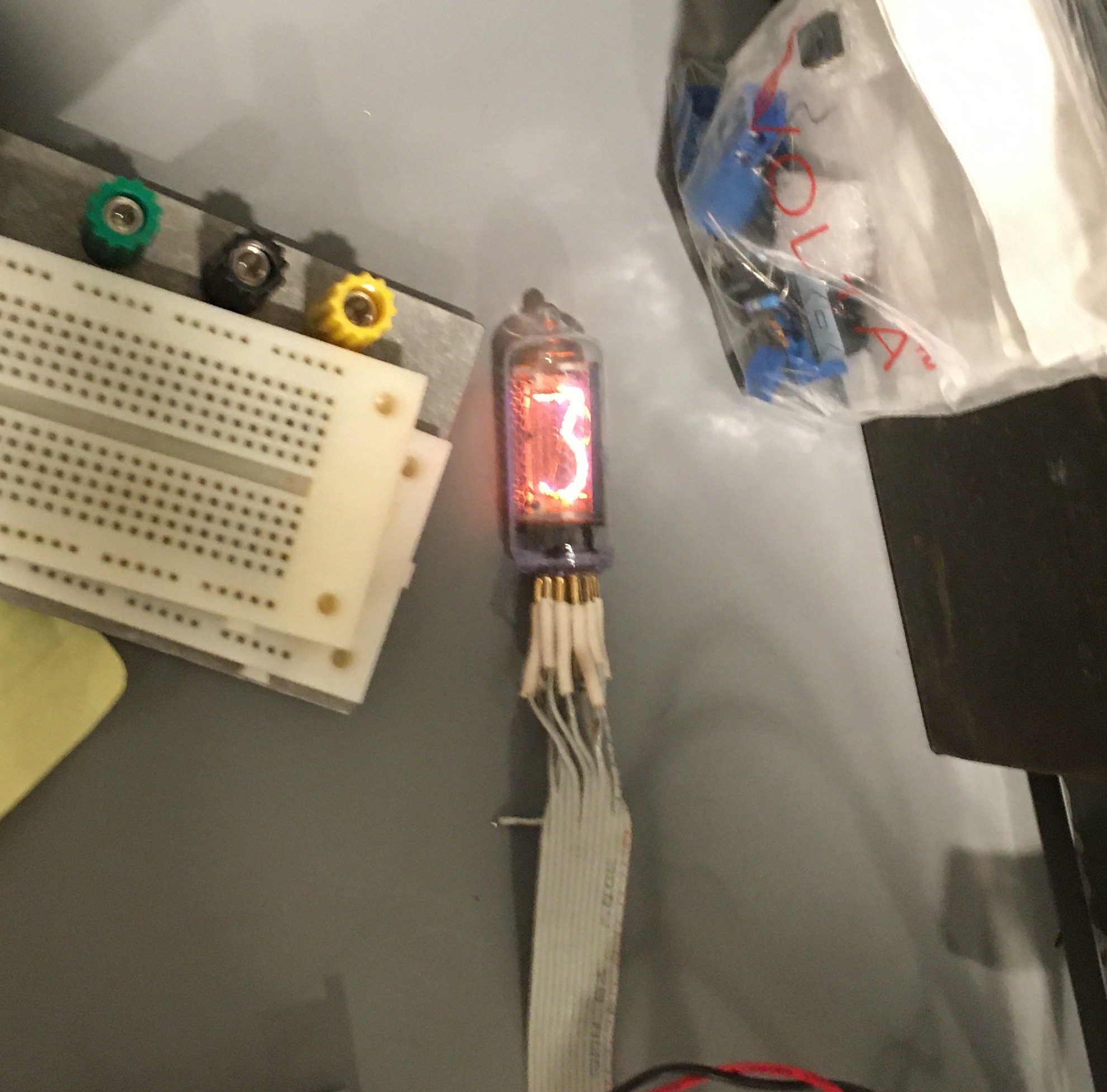 IN-8's are the same size as the IN-14 but with pins instead of wires and normal 5's instead of upside-down 2's. They will be used in my next nixie project, where I focus more on the style than the electronics.
Discussions
Become a Hackaday.io Member
Create an account to leave a comment. Already have an account? Log In.