 dearuserhron
Inspired by this: http://www.electronixandmore.com/projects/relaycomputer/ <- the simplest circuitry for relay computers out there.
To add two numbers, one have to press buttons simultaneously according to the conversion table (on the left), and hold them. The sum of two numbers will lit. I have had no push-buttons by hand, so I made one myself using tiny limit-switches and furniture parts. Large nuts are on glue, not to be screwed.
Most other designs have relays driven by carry logic. This leads to slow carry propagation. In my device relays are connected to the inputs, not carry, so carry wire gets passively switched. Bottom relays are connected both to A and B wires using bridge principle, therefore acting as a XOR function. Upper relay is operated by B wire and perform additional switching.
Green "C" bulb indicates carry flag. You got it right.
Pink "E" bulb is more tricky, it indicates signed overflow flag. See upper (blue) conversion table.
Wooden case is not mine, it was my friend who made it especially for this device.The whole thing was made with the goal in mind to sell it via souvenirs shop, but then I decide not to sell it, because nobody will buy it. Instead I will carry it with me and use it for demonstrating purposes.
That big wooden part at the bottom is used to reduce accidental pushes. I can put the device into my backpack and be sure it will not discharge itself.


 Stefano
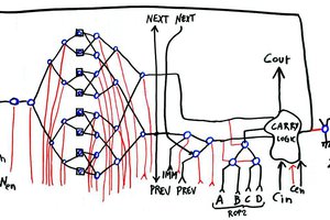
 Yann Guidon / YGDES
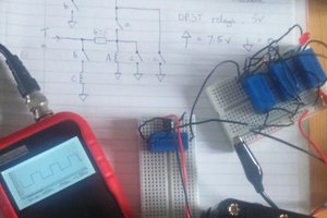
 will.stevens
Welcome to the club :-)
Maybe some other projects at https://hackaday.io/project/11798-relay-based-projects will inspire you ?