 Chris
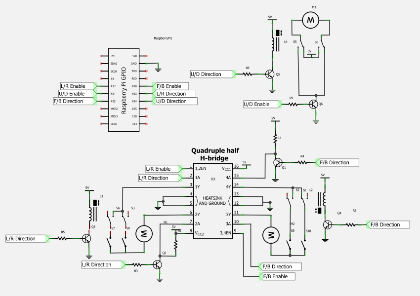
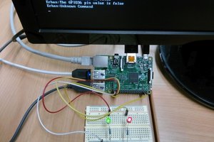
ChrisUsing a Raspberry Pi to control a toy arcade grabbing machine through a webpage with webcam display.
0%
0%
Internet of Grabby Things
An internet connected toy arcade grabbing machine. Created at a Raspberry Pi hackday in Leeds 2012.
Become a Hackaday.io member
Already have an account? Log in.
Just one more thing
To make the experience fit your profile, pick a username and tell us what interests you.
Pick an awesome username
hackaday.io/
Your profile's URL: hackaday.io/username. Max 25 alphanumeric characters.
Pick a few interests
Projects that share your interests
People that share your interests
 erhanyilmaz.ytu
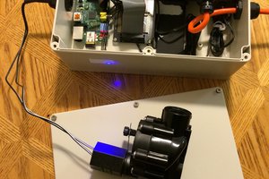
 Glenn Conner
 Steven Hickson
 Jon Hobbs