 Lauri Pirttiaho
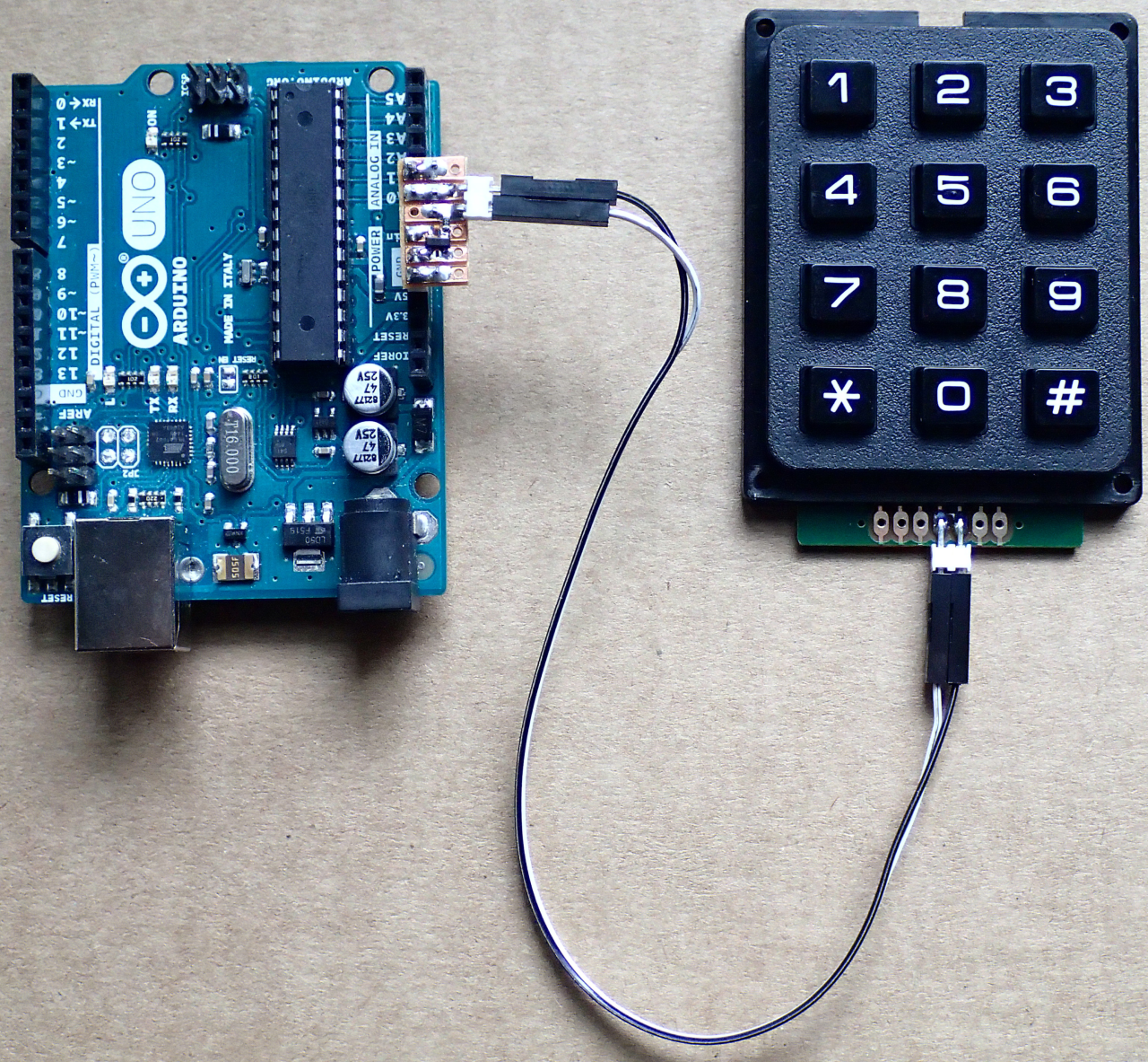
The Keypad
Keypads, numeric or otherwise, are typically manufactured as push-button switch matrices, switches being located at the cross-points of the column and row lines which then are accessible through the keypad's interface connector. Similar key matrices can be constructed also from discrete push-button switches and the externally visible layout does not need to be square. In all cases, in order to minimize the complexity it is advantageous to arrange the wiring such that the sum of the rows and columns is minimized.
A keypad so constructed is intended to be interfaced digitally. The states of the buttons are decoded by scanning the switch matrix rows one-by-one and reading the columns (or vice versa) in parallel. This can be done from a microcontroller's GPIO or from a dedicated keyboard interface driver chip, or one can use shift registers or serial-to-parallel and parallel-to-serial converter logic chips (TTL, CMOS, LVC etc.).
If one wants to connect such a switch matrix with less pins, a common approach has been to connect the switches into a resistive voltage divider, each button press creating a different resistor combination topology and thus a different output voltage. For custom made keypad reasonably distinct voltage levels can be achieved by using many resistors of finely selected values. An example of such is available for purchase and more examples can be found in designs of consumer electronics devices like push-button interfaces of some microwave ovens an TV-sets.
If one wants to connect a readily available matrix keypad the same way, either heavy internal modifications are needed, or, when using only the externally accessible connections to the rows an columns, even with careful selection of the resistors, it is difficult to get the spacing of the output voltage levels uniform, which requires more complex decoder program and in some cases unit-by-unit calibration and even then the performance with large number of keys is not very good.
What is needed is a way to generate uniform distribution of voltages with a simple circuit.
The Modification
Both a custom key matrix and an off-the-self matrix keypad can be easily modified to produce a uniform distribution of resistances by connecting resistors between consecutive rows and columns. Only two different values are needed, one for rows and one for columns. The resistance of a resistor between rows must be number of columns times the resistance of a resistor between columns (or vice versa).
Such exact resistor value ratios are available in standard resistor values from series E24 and up. Required tolerance depends on the total number of keys. Tolerance of 5% is sufficient for 3x4 matrix while for 4x4 it would be safer to use 2% for manufacturing, even though usually 5% is also OK, at least for private projects.
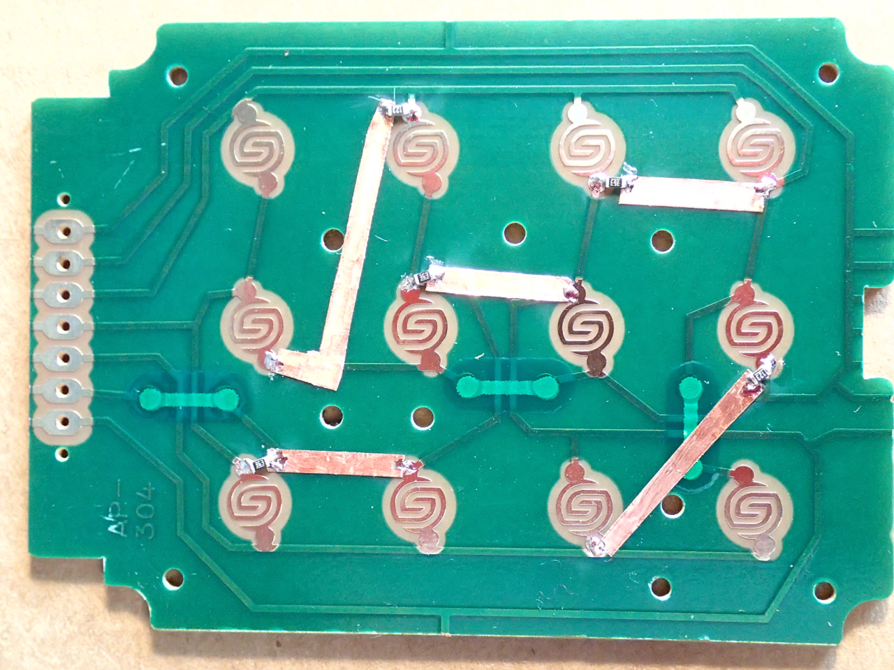
One of the photos shows the circuit board of a rubber dome keypad which was used in the demonstration. That board contains an internal modification made using five 0402 resistors (12 kΩ and 36 kΩ) connected between the rows and the columns using slug tape. external modification can be made to the pins easily if the connector uses the pattern where row and column lines are not interleaved. This keypad has them interleaved so the modification was made internally. In commercial productions the resistors would be part of the board and the connector would have only two pins. An alternative would be to use an adapter board attached to the keypad's connector and providing the two-wire connection onward.
The Interface
At the logic board, between the keypad connector and the analog input pin of the microcontroller a simple current mirror circuit is needed. That requires just one resistor and a current mirror, like BCV61 or a pair of transistors, co-packaged, like BC847S or discrete. Pretty much any pair of similar transistors is sufficient for private projects, but for manufacturing a dedicated current mirror is a better...
Read more »
 Krists
 David Levi
For a discussion about using a high side current mirror, please see https://github.com/sgmne/AnalogKeypad/issues/1
In some cases the mentioned easier noise handling and the short-circuit protection could be a strong advantage for such inverted design.
Other suggestions related to measuring the base voltage with another ADC channel or using it as a reference, are also worth considering, and in some cases might suit better than the temperature compensation by the emitter resistor and relying on narrow variation of the current mirror parameters.