 deʃhipu
How do you deal with insomnia? I design PCBs when I can't sleep. Tonight is such a night, so I decided to finally take a first stab at a new version of a PCB for Fluffbug.
There are quite some changes required. The SAMD21 microcontroller and all the supporting passives, together with the Feather headers go away. They are replaced with headers for plugging in a Wemos S2 Mini development board. The servo sockets get replaced with sockets for the ribbon cable plugs — they have the same footprint, but physically they are much larger and will require more clearance. The power switch, battery charging, battery protection and piezo speaker stay. I decided to remove the IR sensor, since we will have WiFi (or ESP-now) for communication.
Next, there is the problem of placing all the components in a physically possible arrangement. The placement of the S2 Mini is the greatest problem. On one hand we want it to be central, so that any shields plugged into it can act as the robot's "face". On the other hand, we want the USB socket to be accessible, the antenna to be as far away from the servo motors as possible, and the reset and boot buttons not completely covered. It's a lot of constraints, and I came up with something like this:
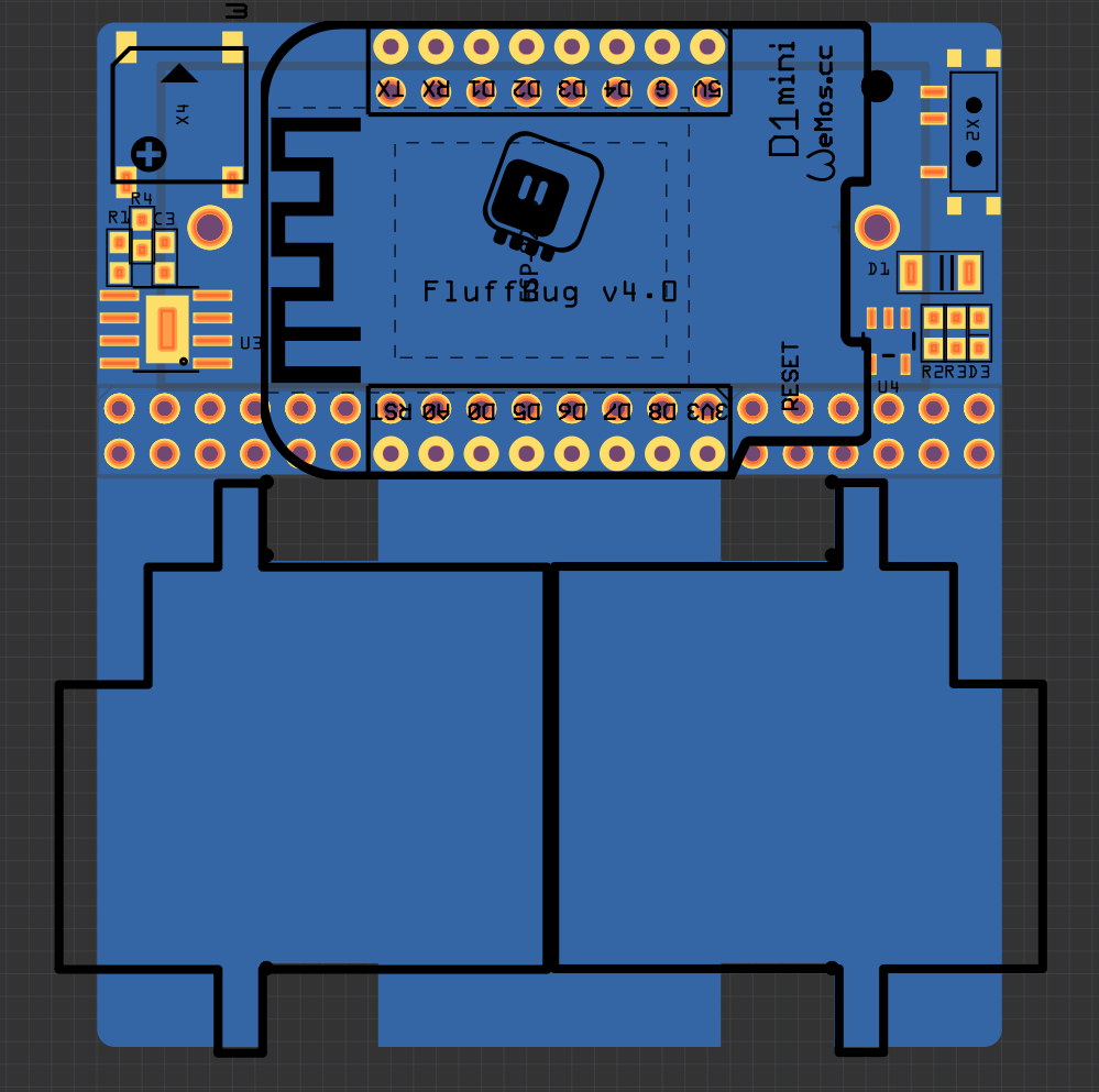
On the back of the PCB is the battery holder, and the two sockets for the ribbon cables for the servos. Since the battery is round, there should be enough clearance for the cables there. On the front we have the S2 Mini in the middle, with the USB socket to the side, and the antenna on the other side. Obviously a vertical arrangement would have been more convenient, but then the antenna practically touches the motors. The rest is just the power and the speaker. Since I have the room (the PCB has to be wide enough to fit the ribbon cable sockets anyways), I decided to place them all outside of the outline of the S2 Mini — this way I might be able to make the front of the robot pretty thin, and have more room for shields.
The reset button is a bit hard to reach, but I should be able to press it with a screwdriver or something like that. The boot button (which I can re-use in the code as a user button) is easily accessible at the top of the robot.
I might add an additional socket just above the servos, for connecting any sensors from the legs — we will see about that.
Discussions
Become a Hackaday.io Member
Create an account to leave a comment. Already have an account? Log In.