 sotasystems
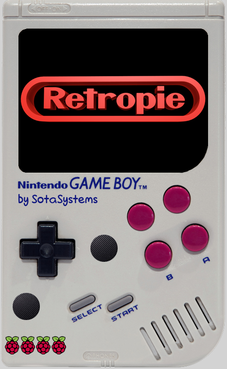
The retropie image was in my case the most appealing and most fun to work with. I have also tried alternative images like recalbox, lakka and some others. The reason I took retropie is that almost everything worked out of the box on the first startup, and to edit configurations if needed is easy to follow, which was important to me because I am less of a "linux guy", but it still is fairly easy to understand what is going on. The interface is nice and clean and easy to handle. So. I was so pleased by retropie and did have alot of fun playing, that an idea I had just totaly got me then. I wanted to put the setup I had on my desk, connected to my TV in some sort of handeld device. Then I saw it. A video of somebody cramming an raspberry pi zero into a gameboy shell. His name is known as "wermy", you can check out his build here:
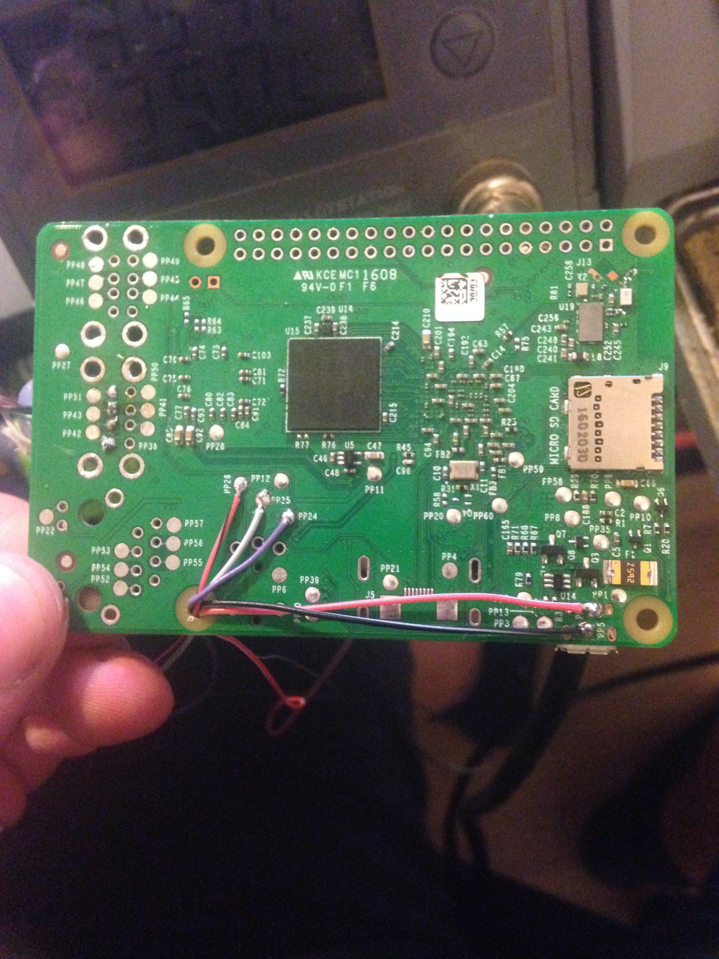
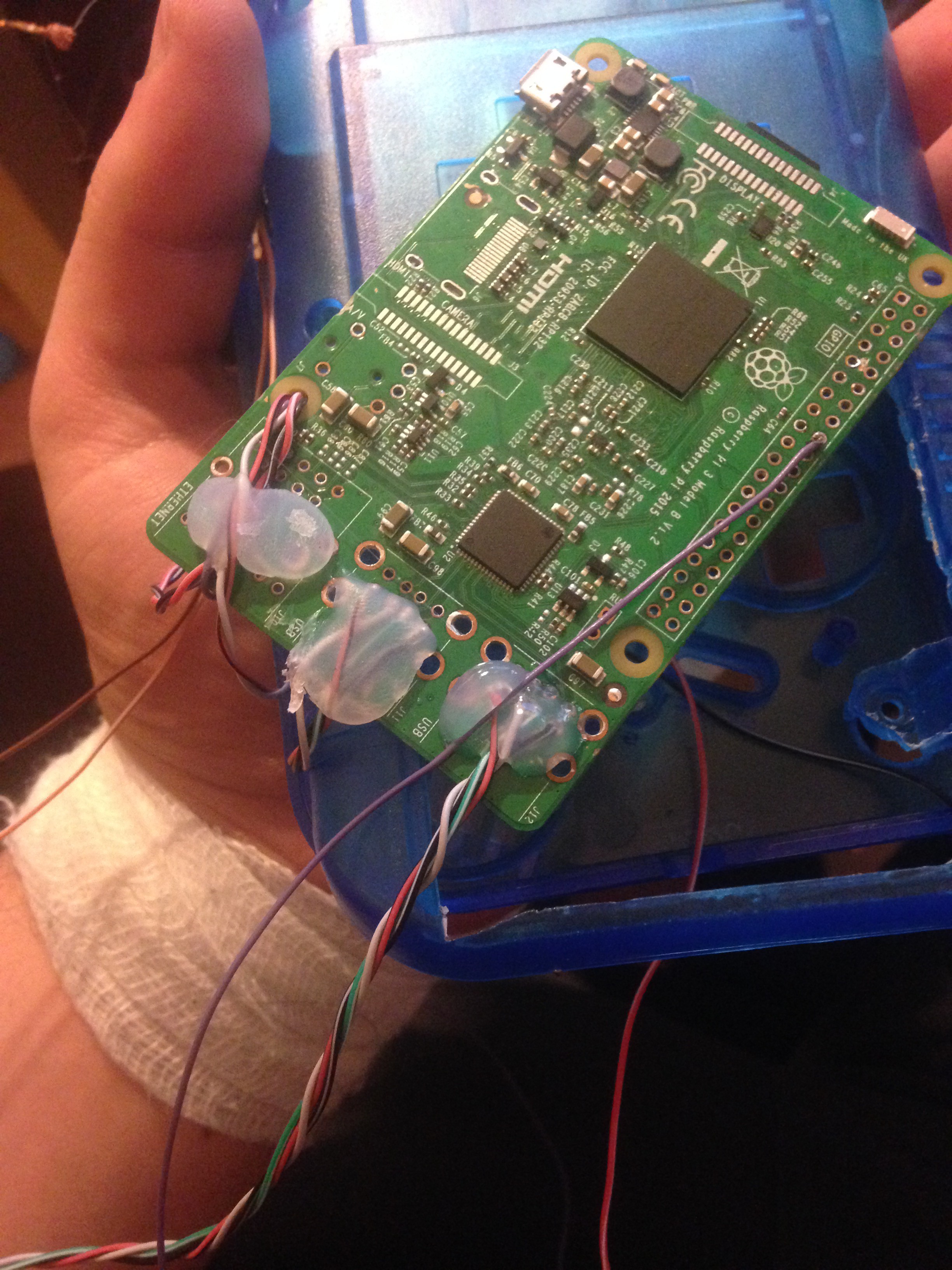
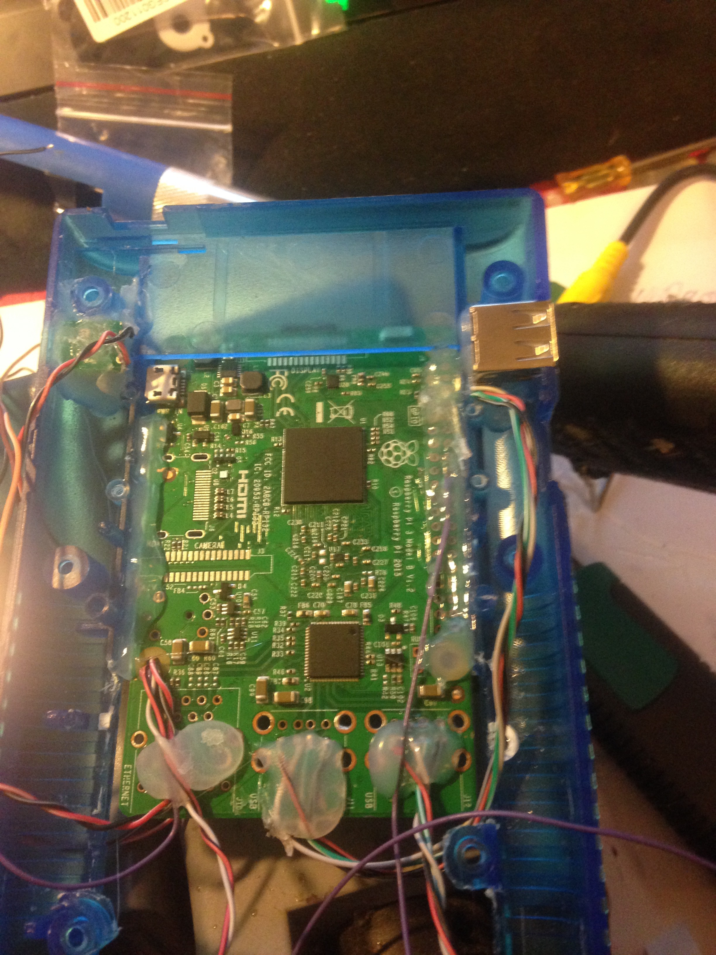
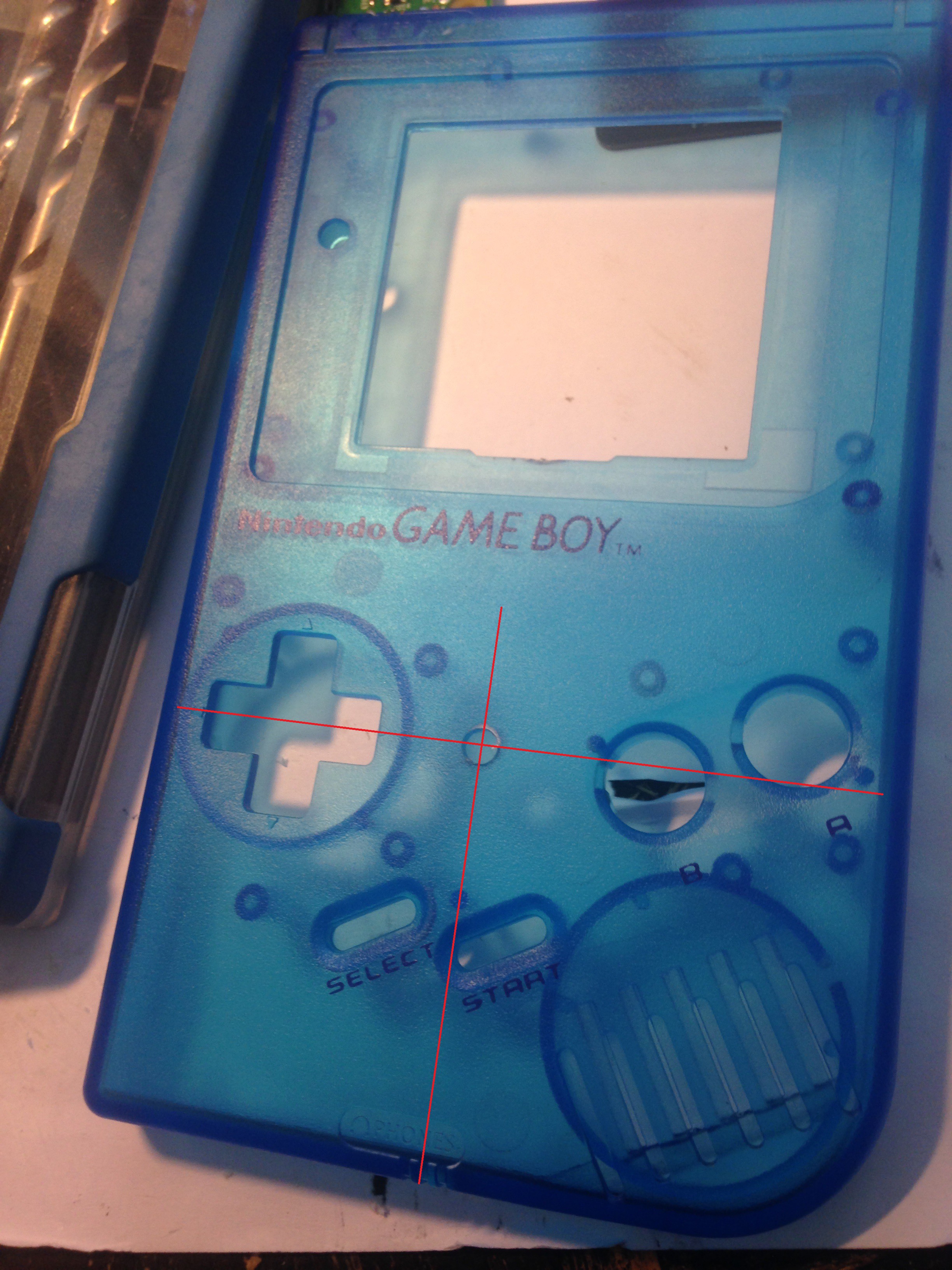
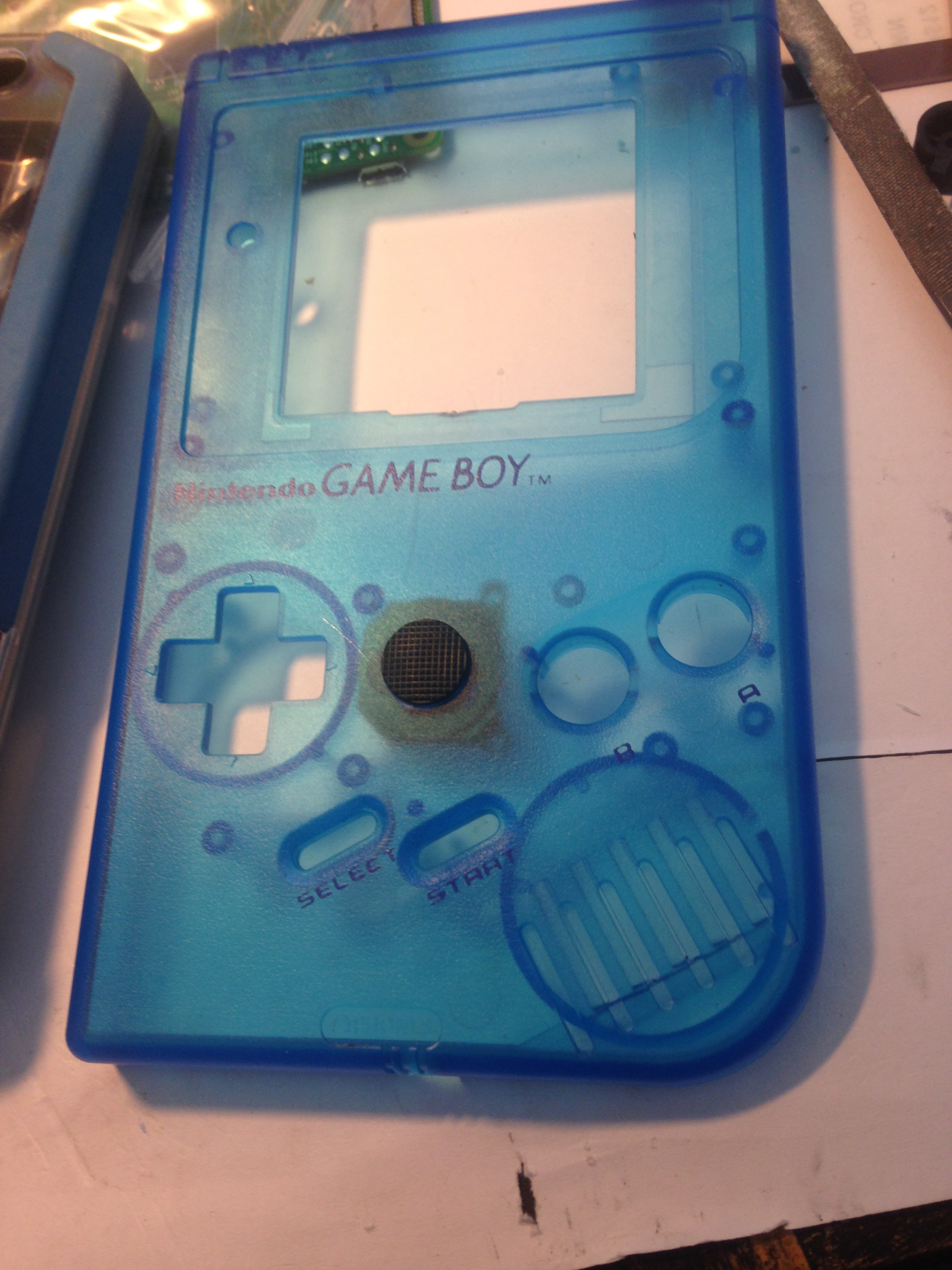
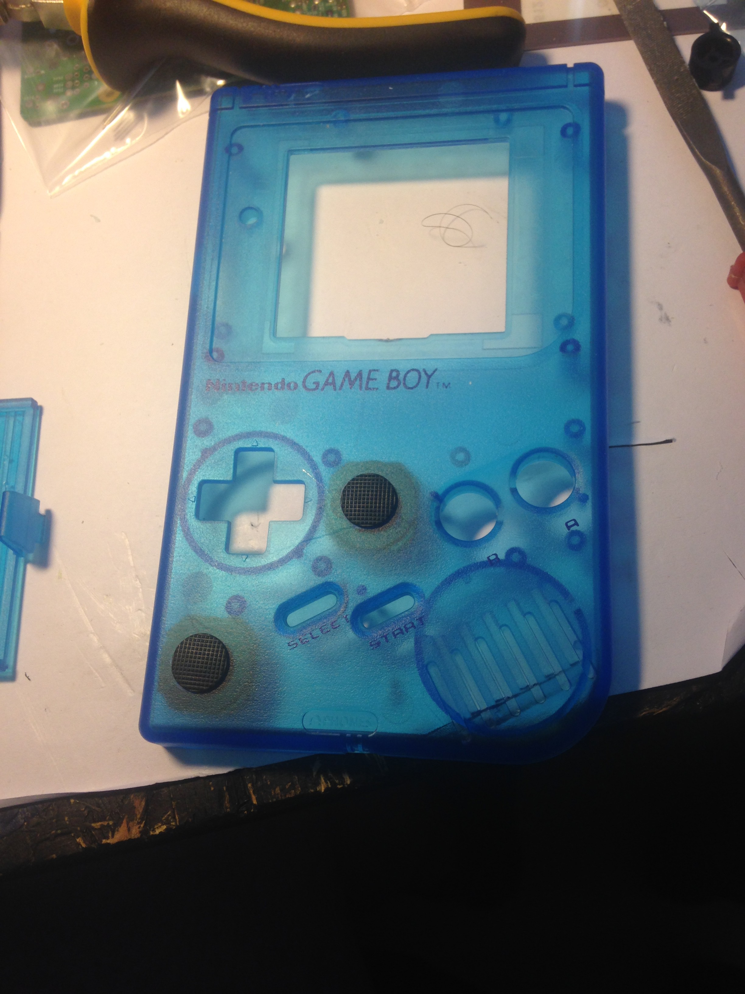
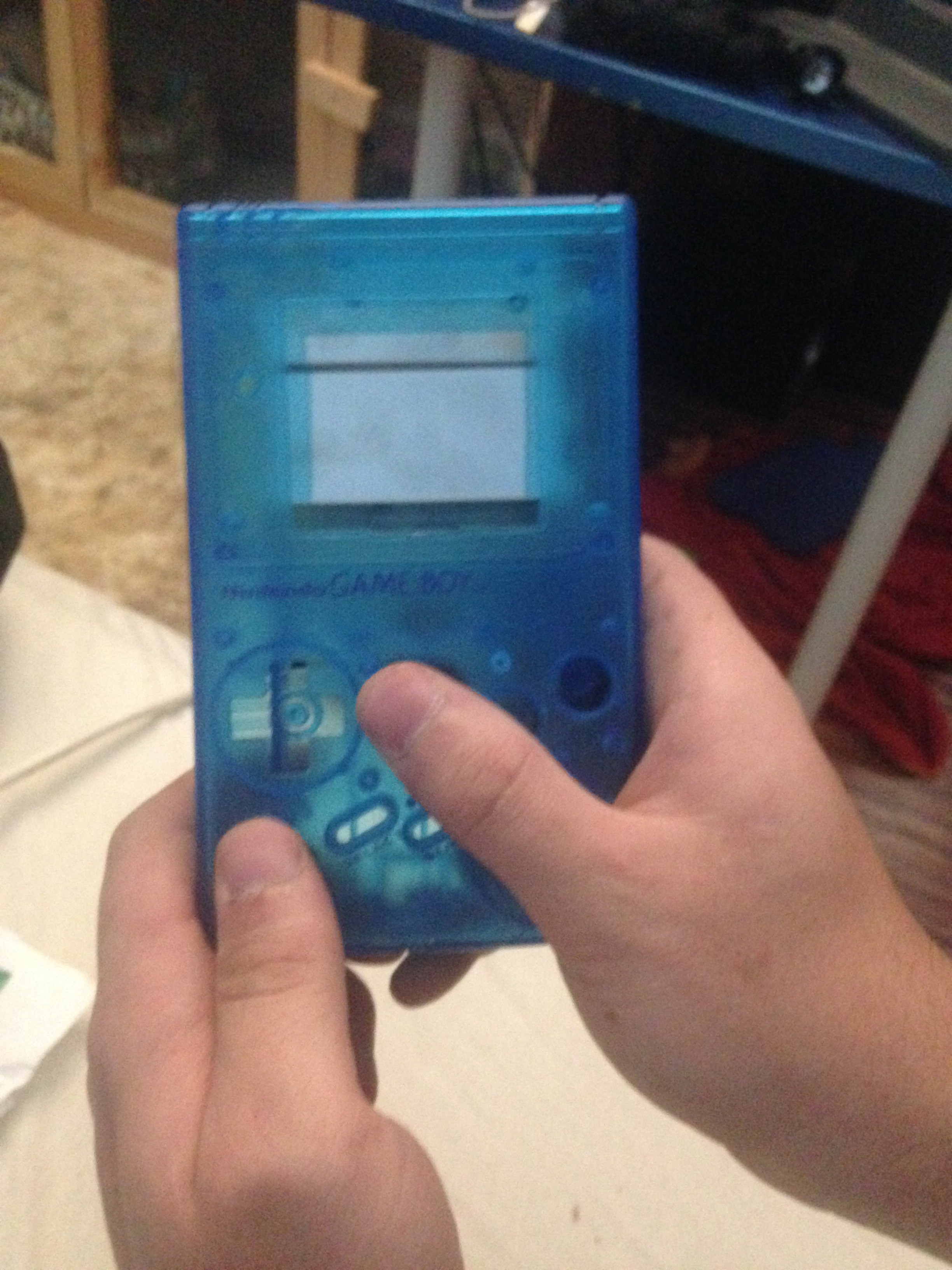
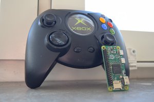
Then there was no going back for me. I knew I had to build something like this! But I wanted to take it up a notch. A Pi Zero was not enough for me, so for extra beef and more features like wifi, bluetooth and more USB, integrated audio and much more, I decided to take my Raspberry Pi 3 for this project. Also, I about had in mind what games I definetly wanted to play on this, so I knew I needed more controls. So I thought about analog sticks, and was like "why not?". So I decided to take two PSP 1000 analog sticks to have one as sort of "main" stick and the other as additional sort or "control stick", sorta like the Nintendo Gamecube. So I took my old gameboy in my hands and thought where to best place them. So then I came up with a prototype sketch (sort of) I have made in photoshop and this is what it looked like:
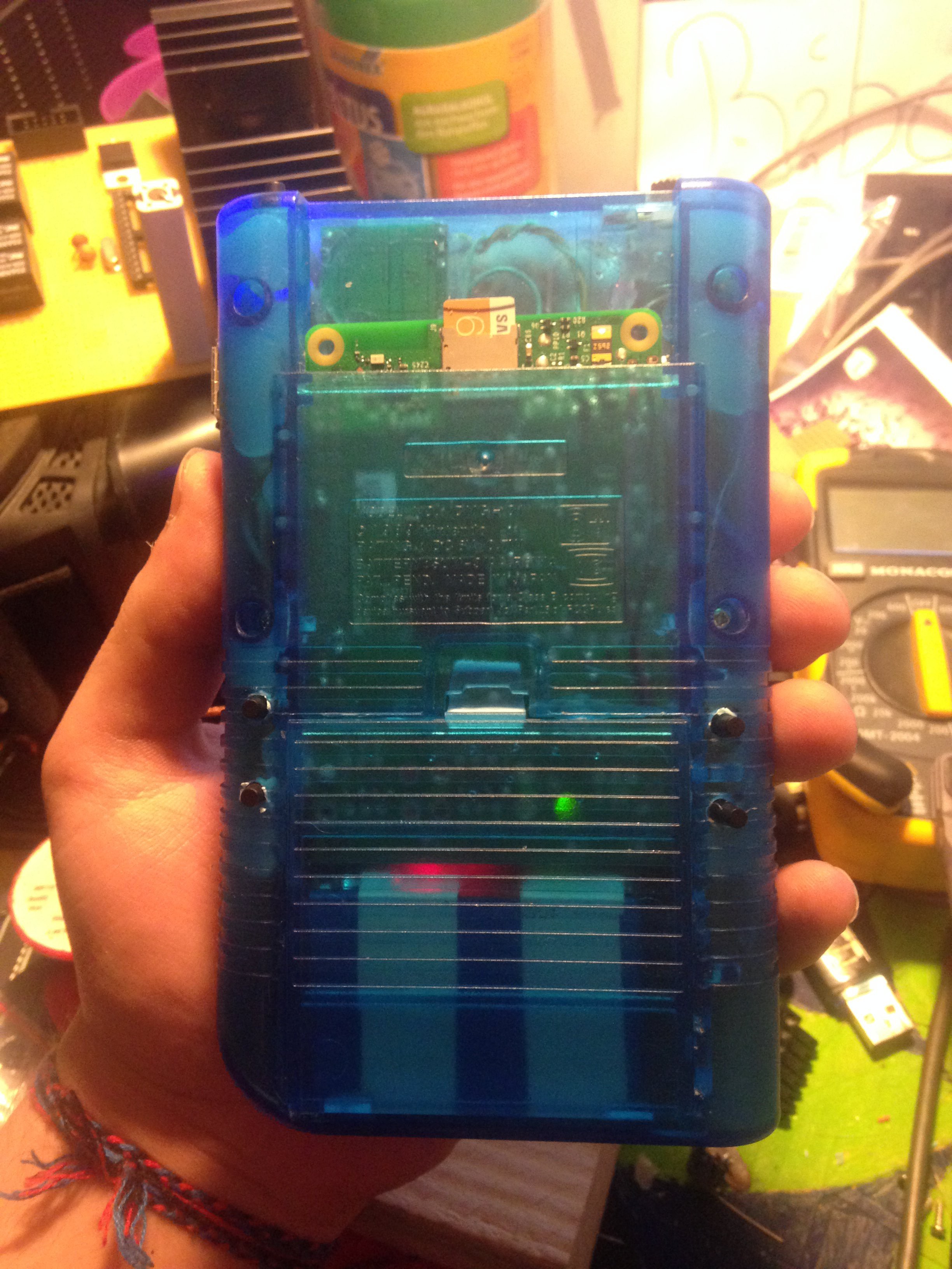
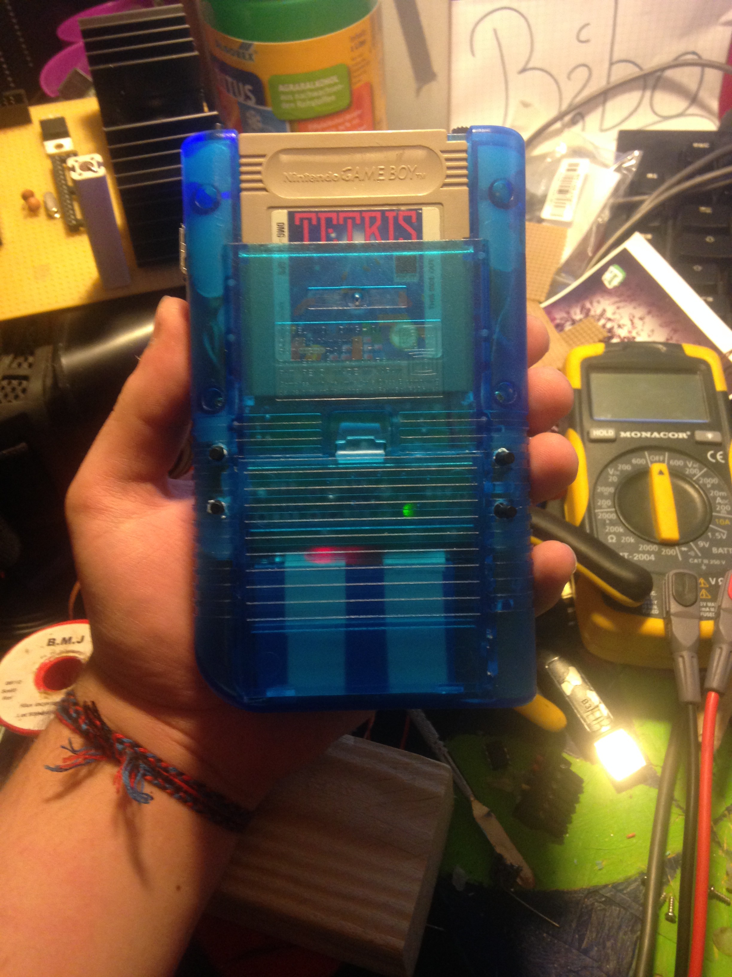
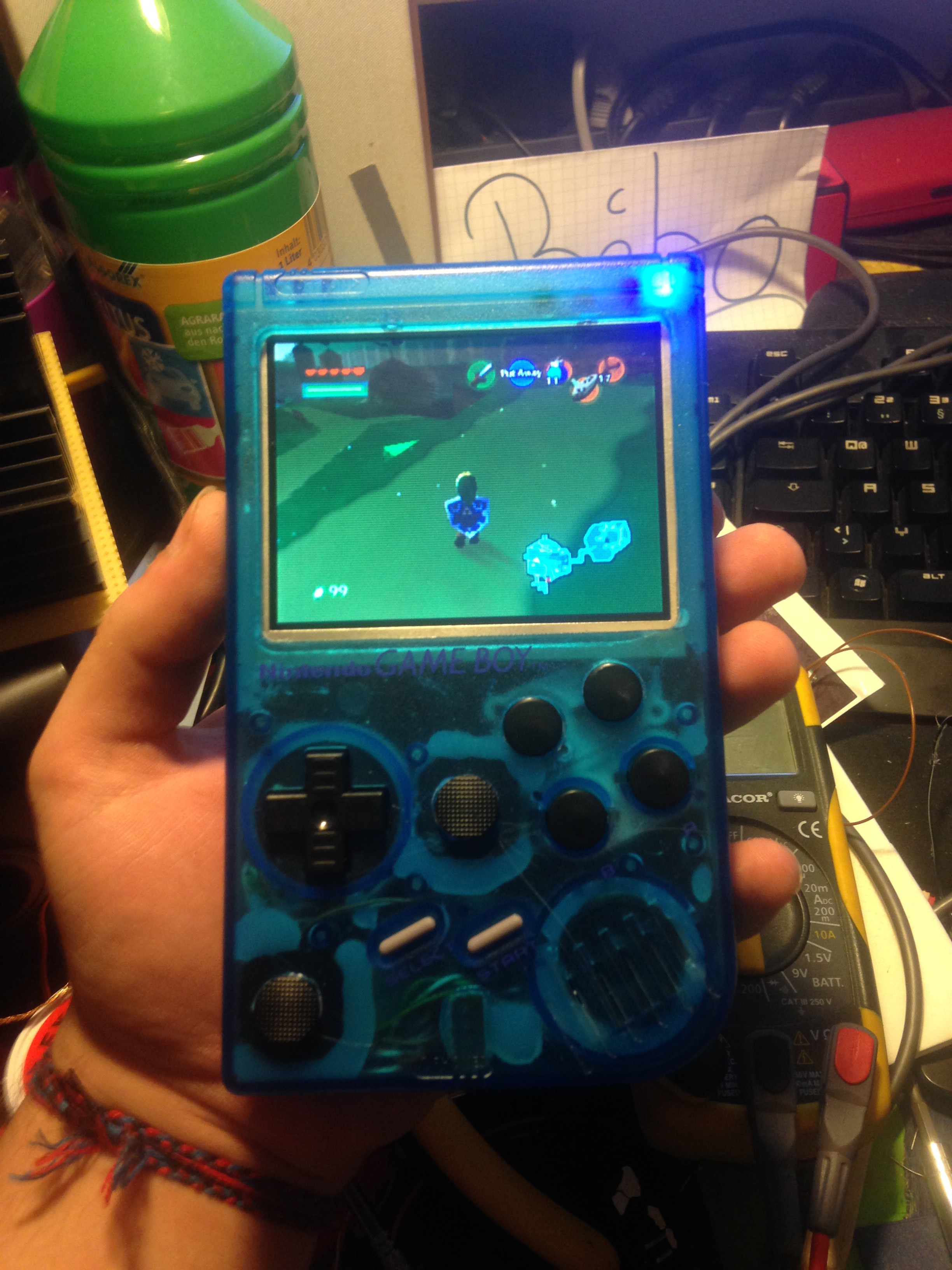
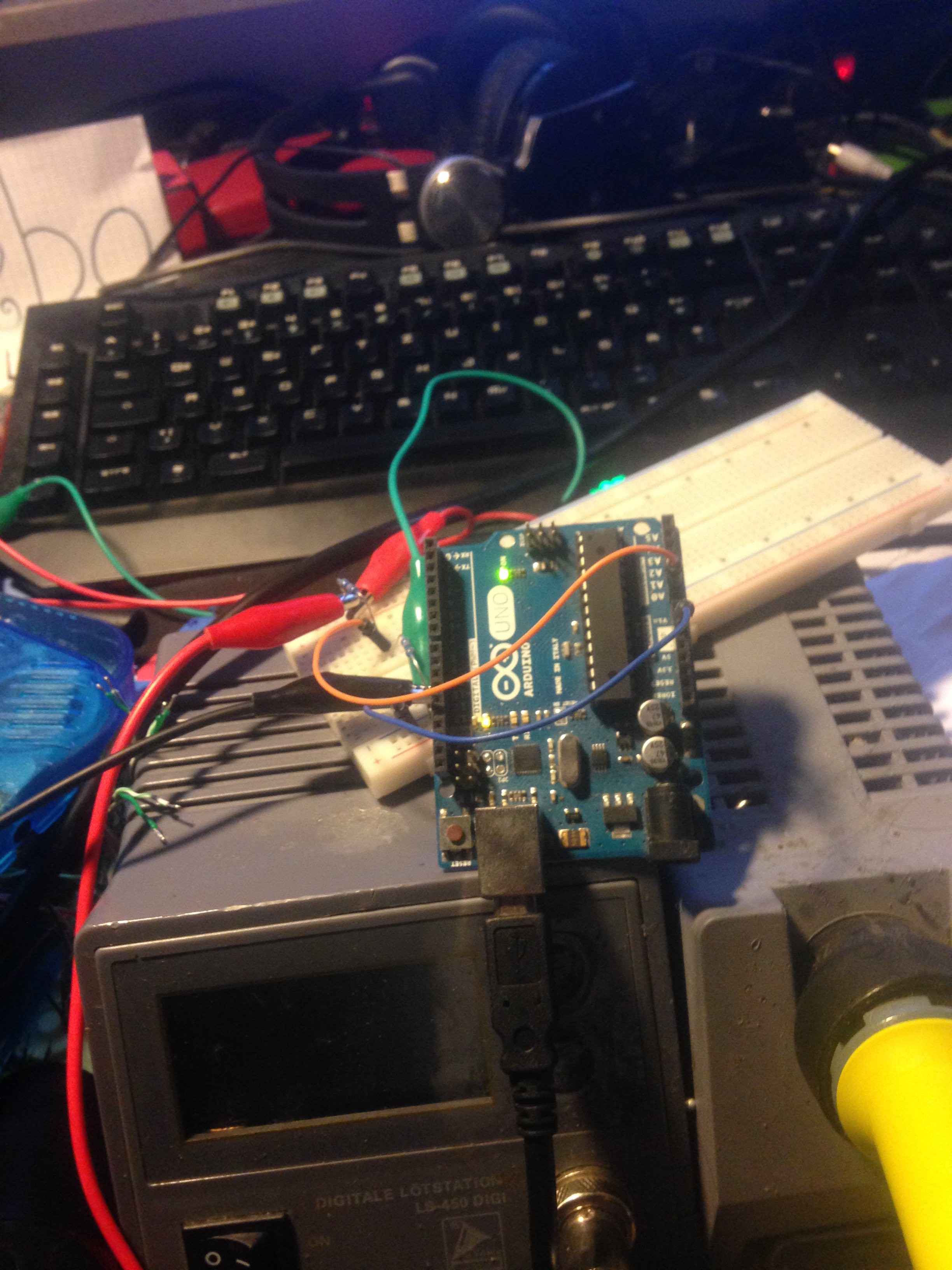
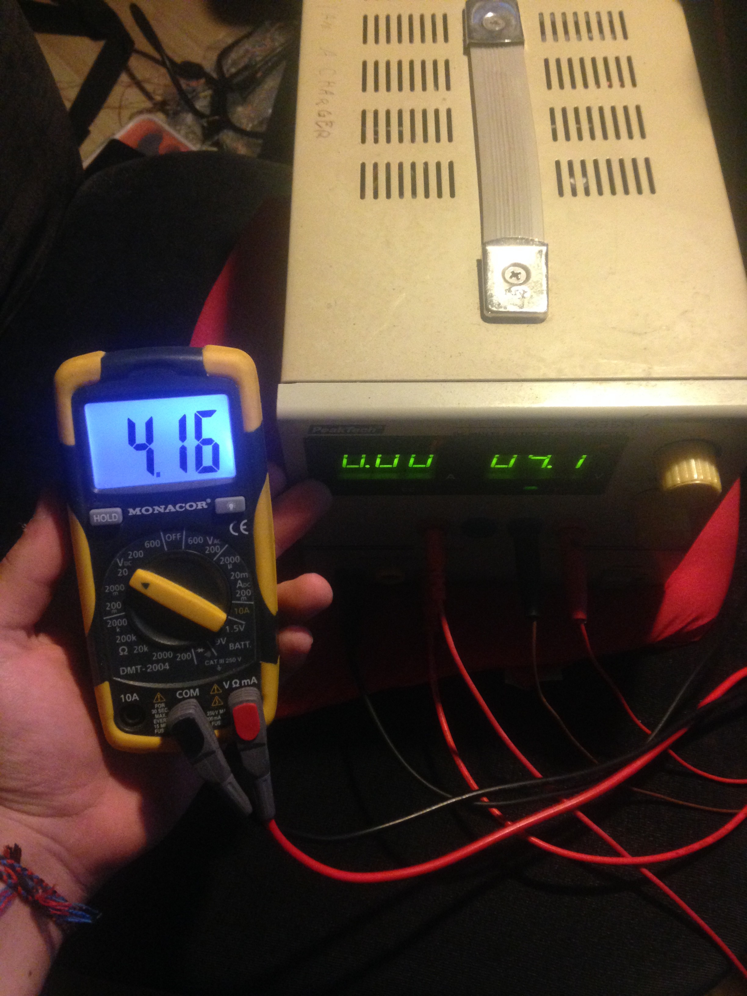
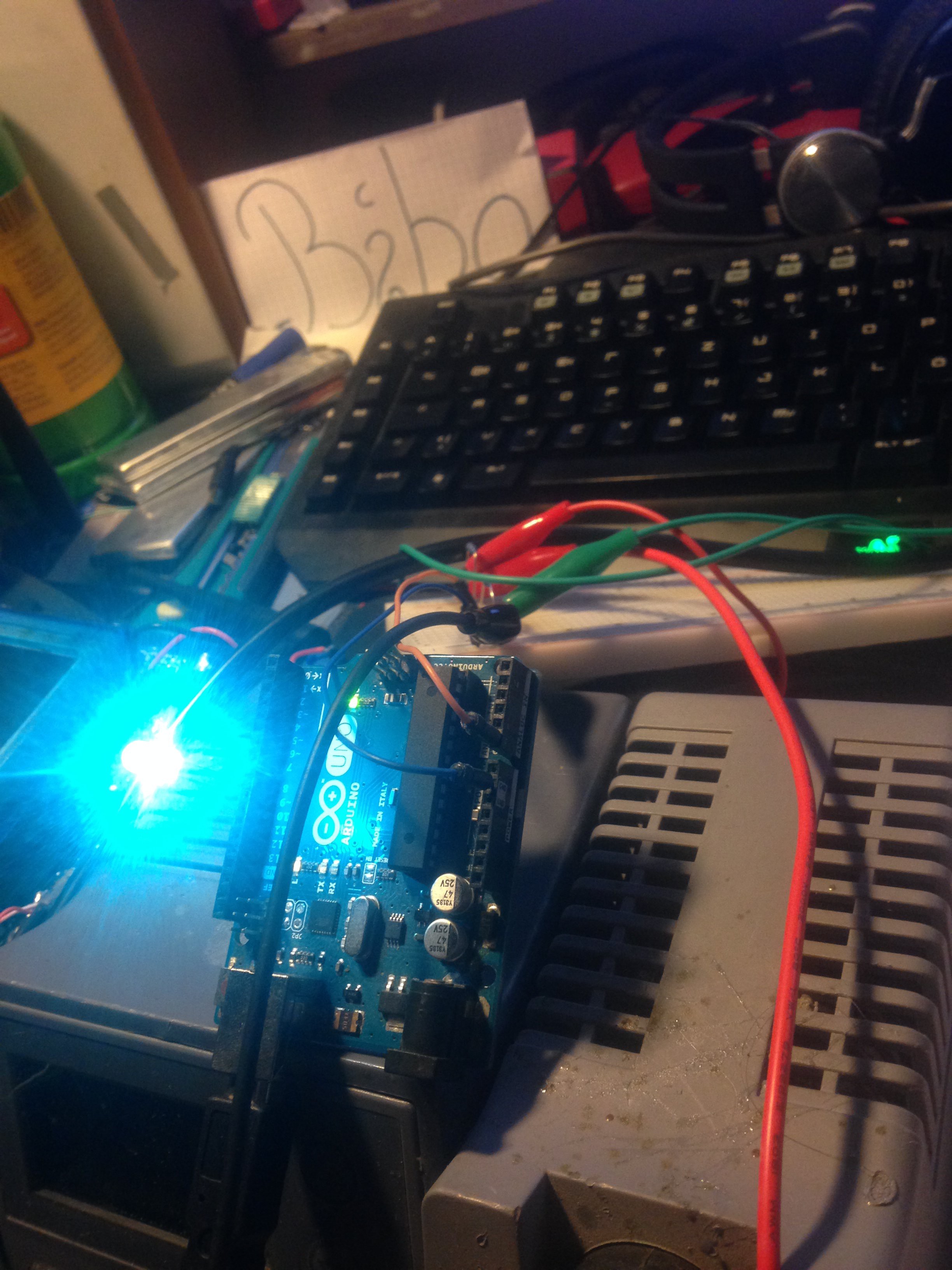
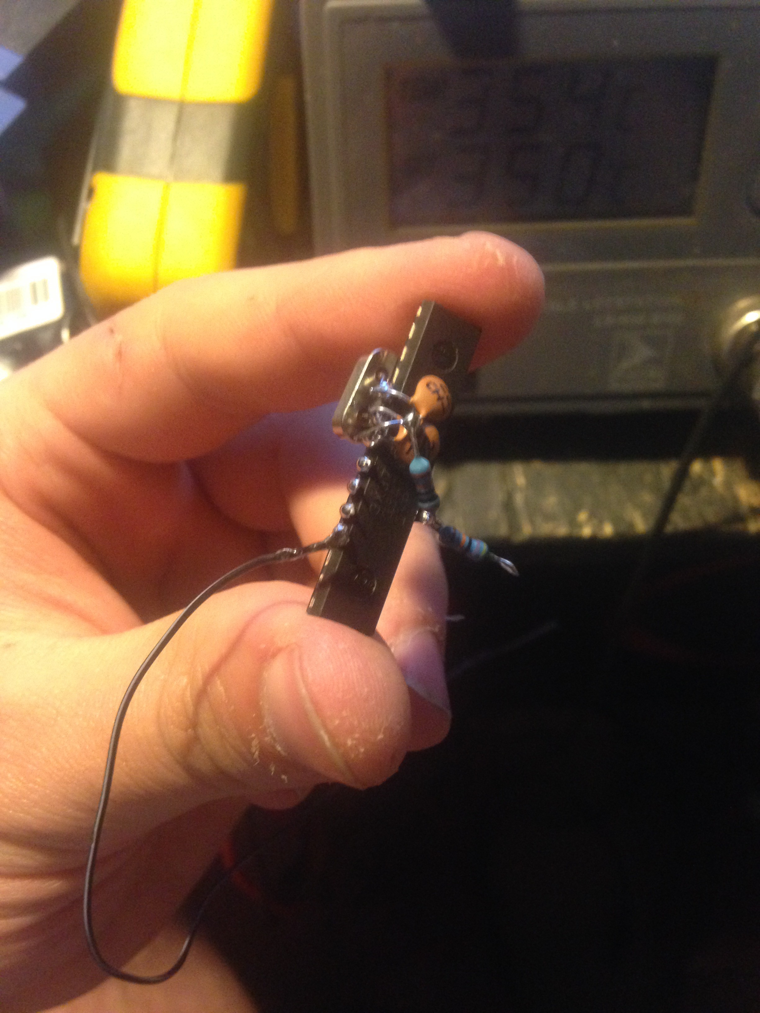
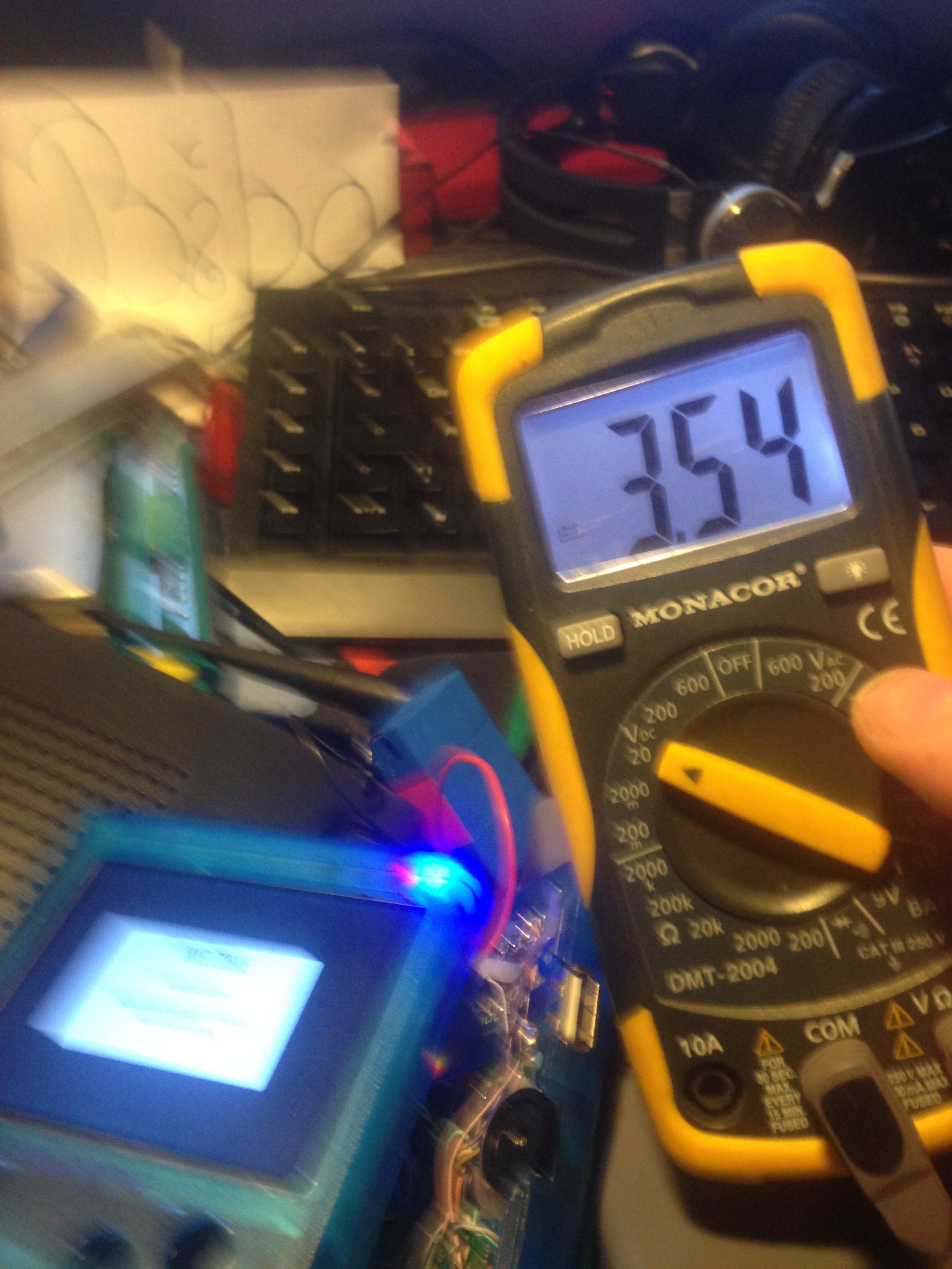
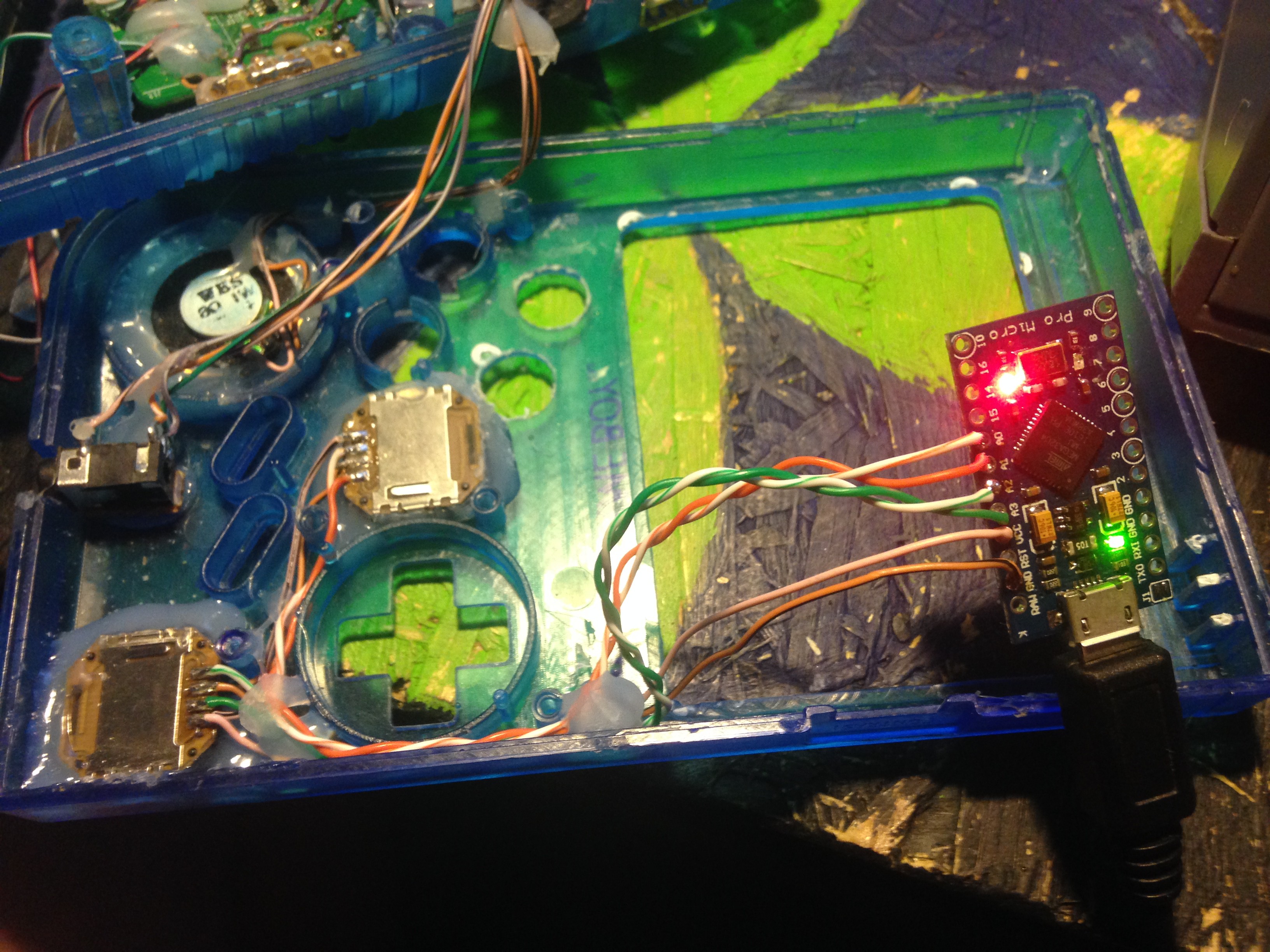
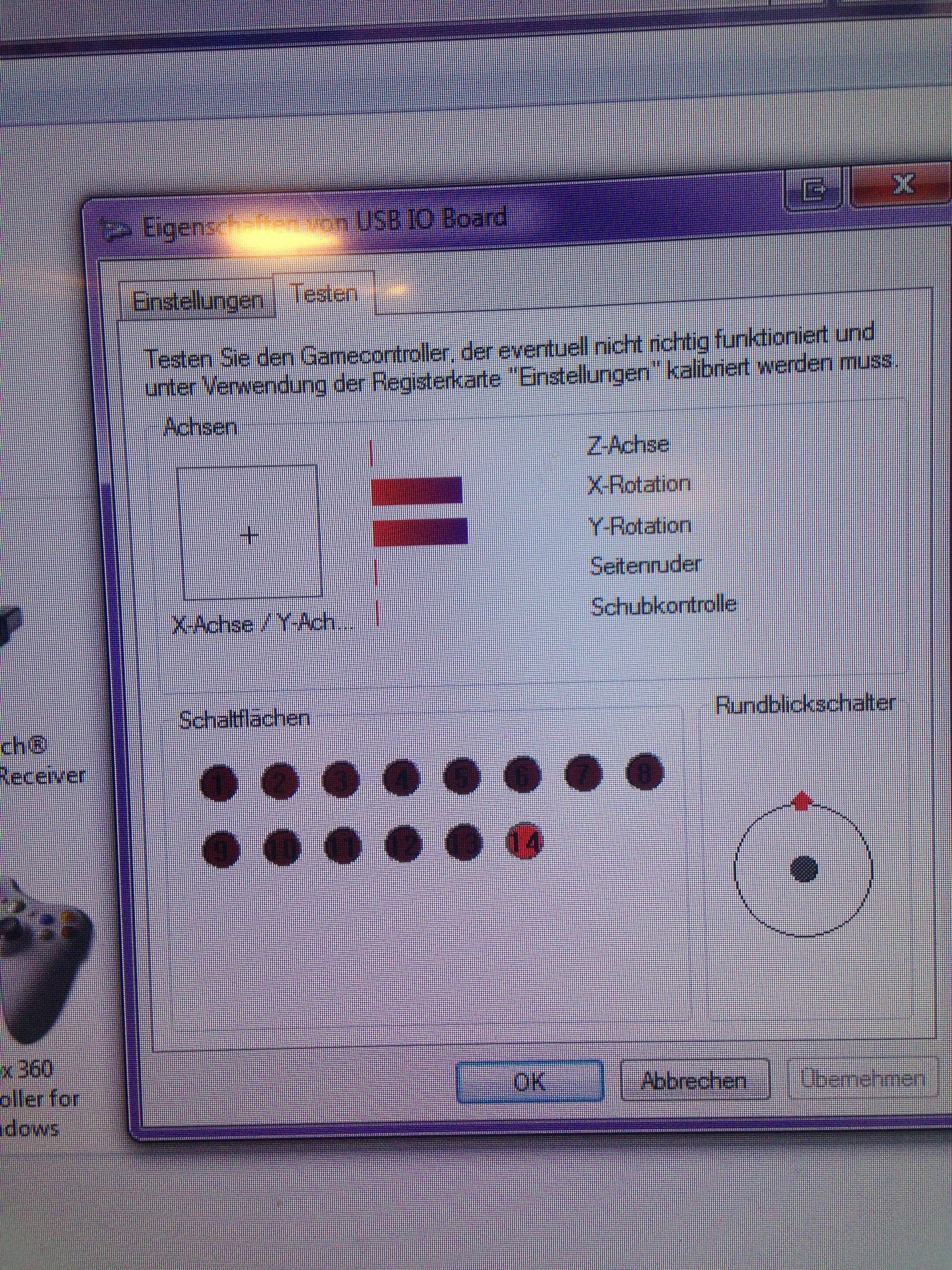
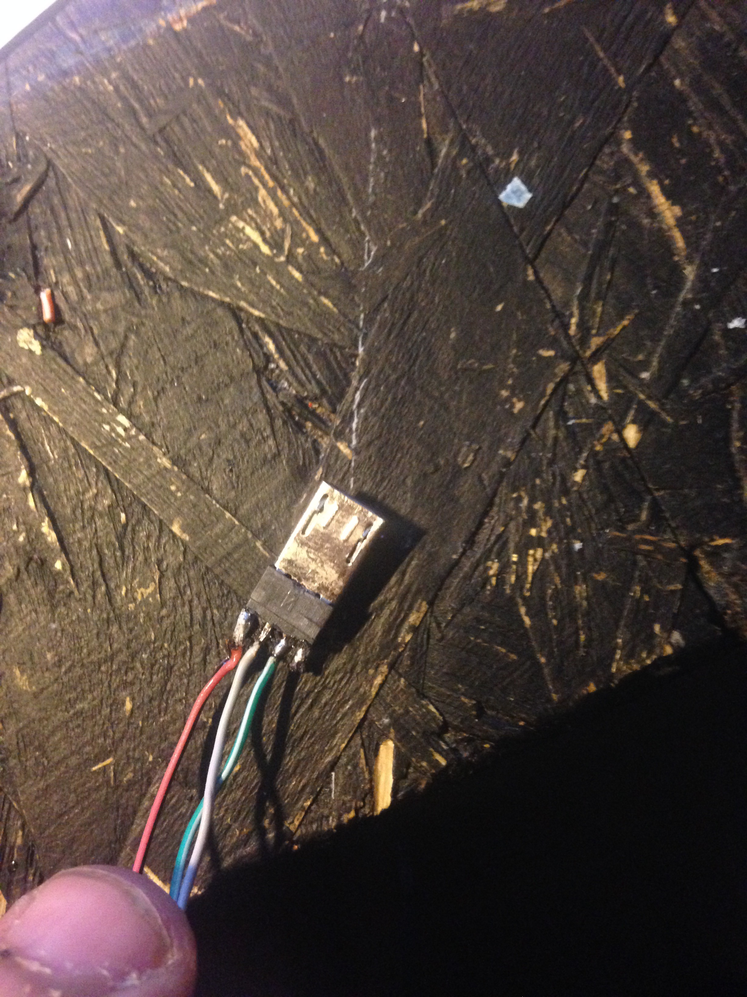
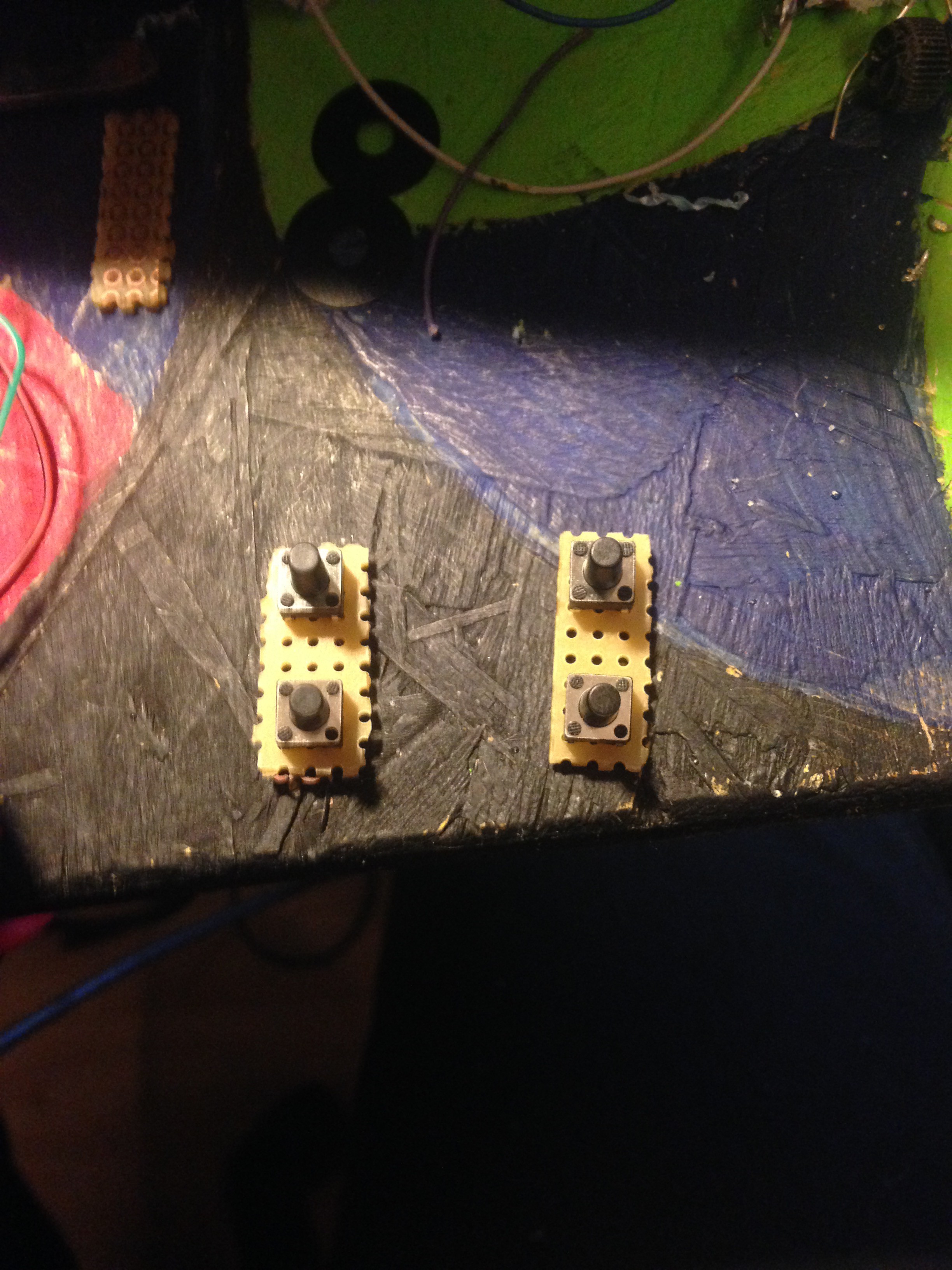
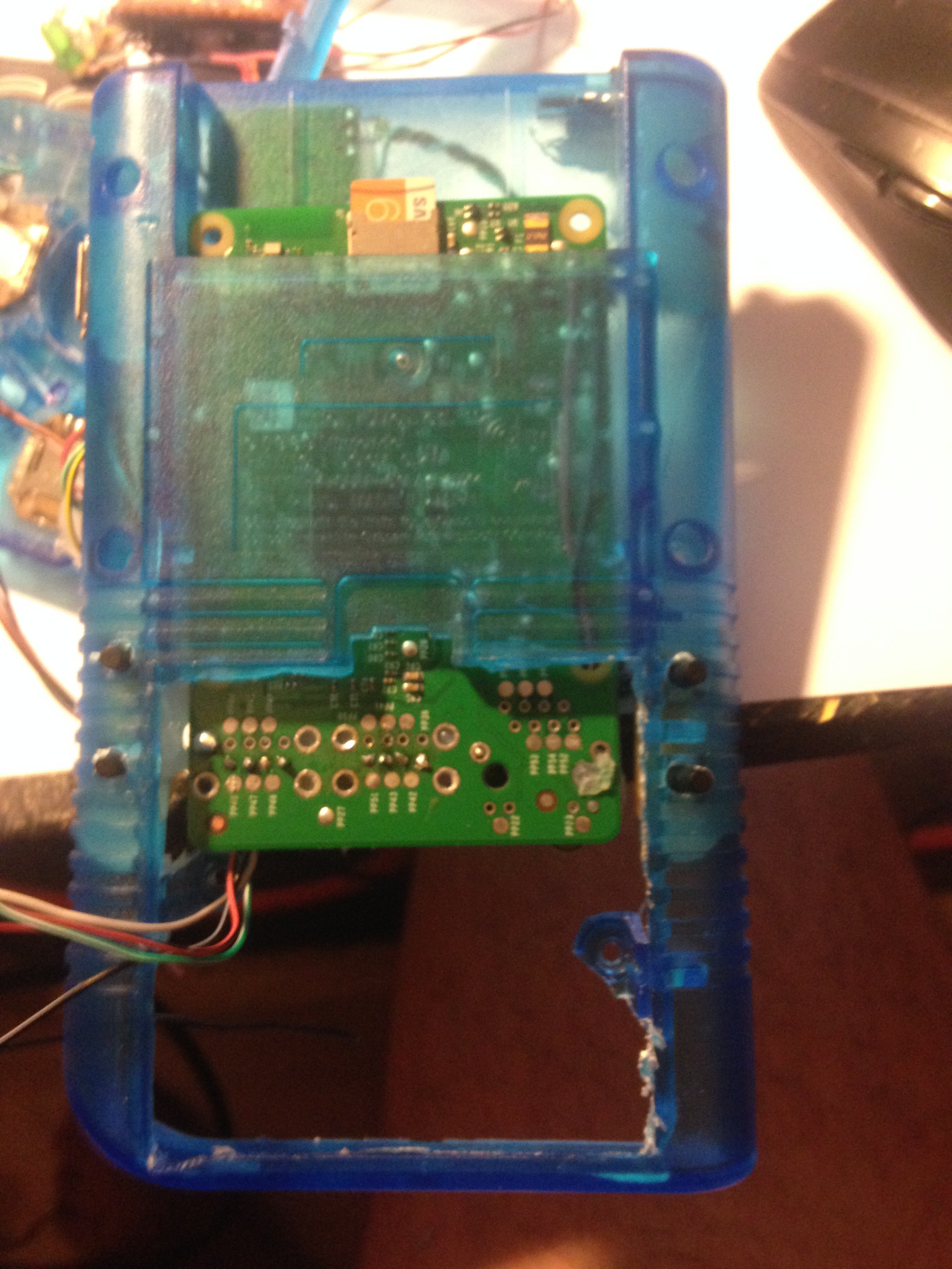
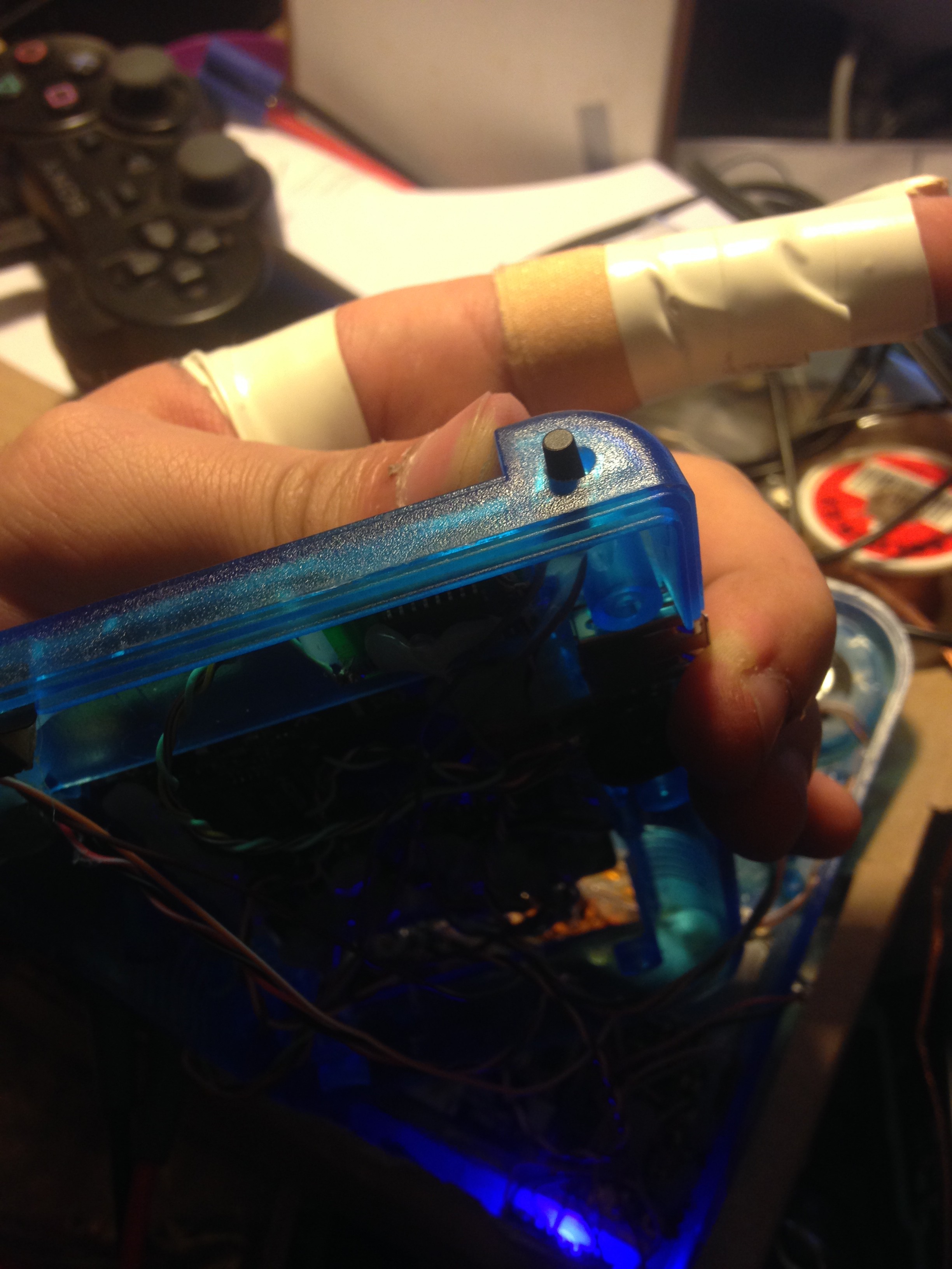
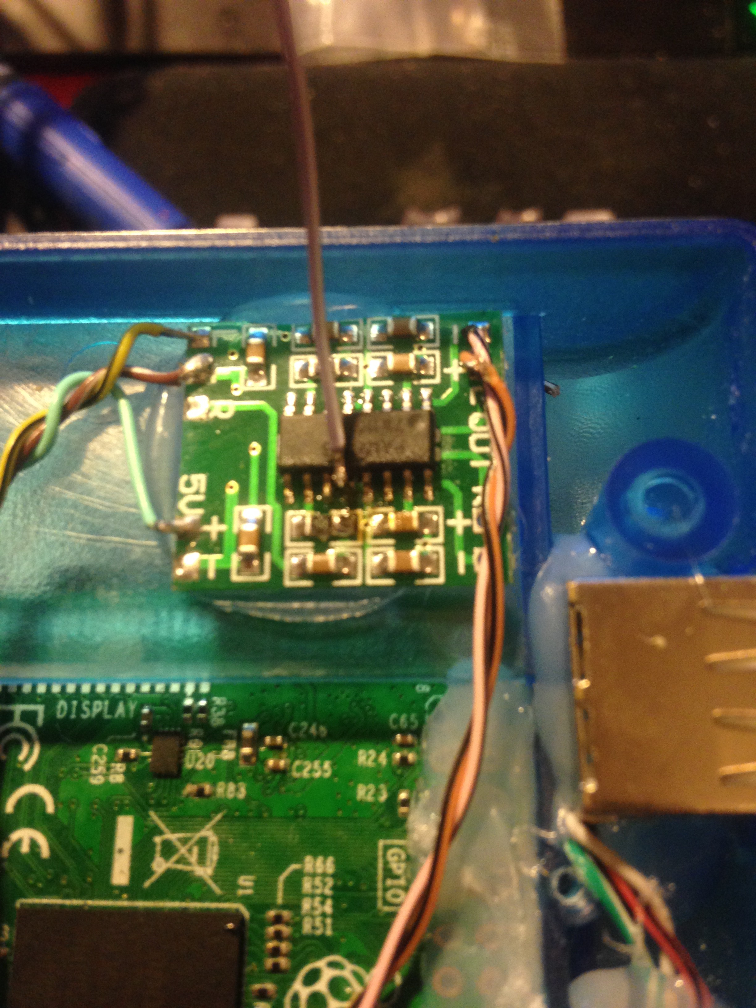
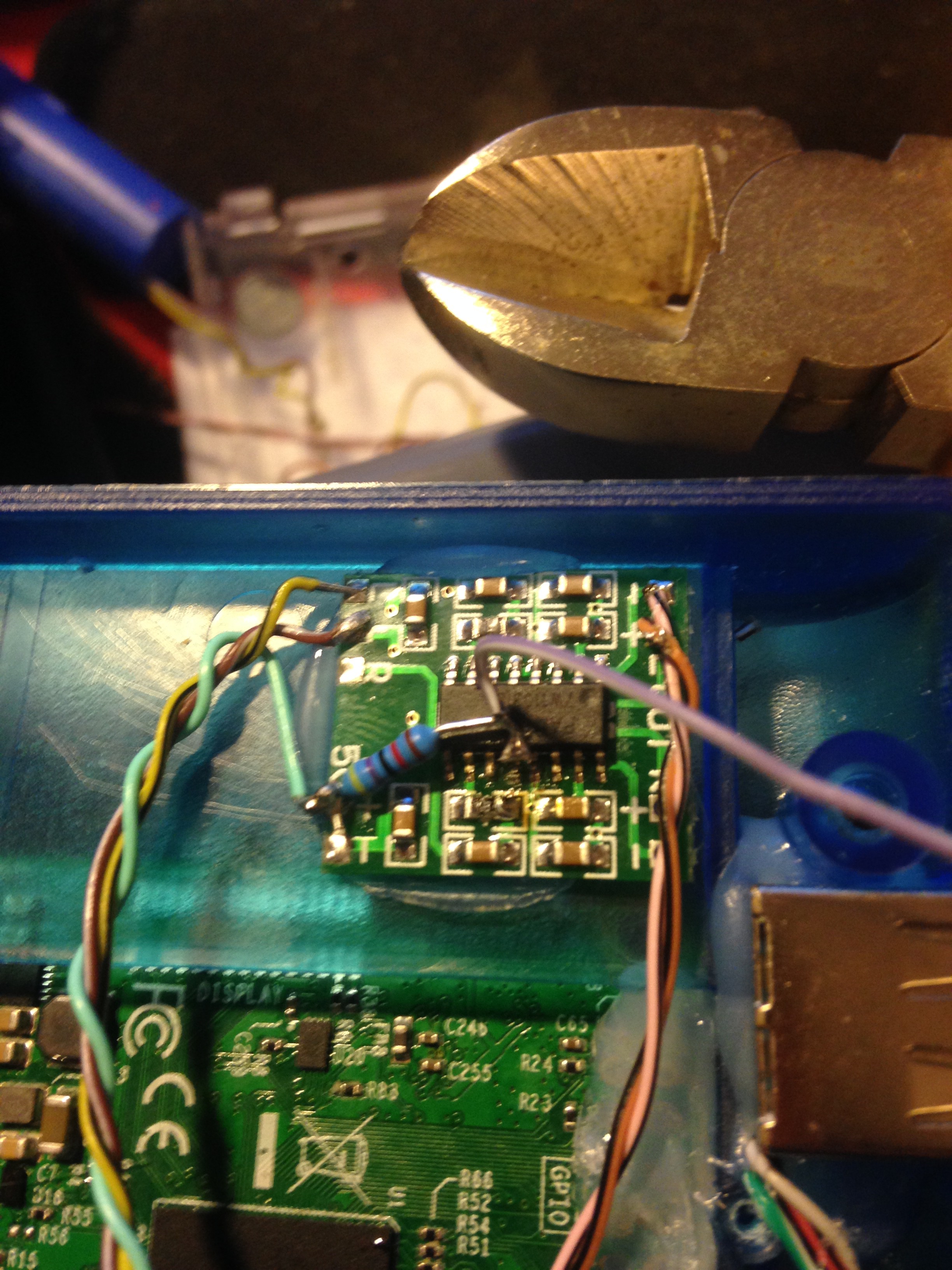
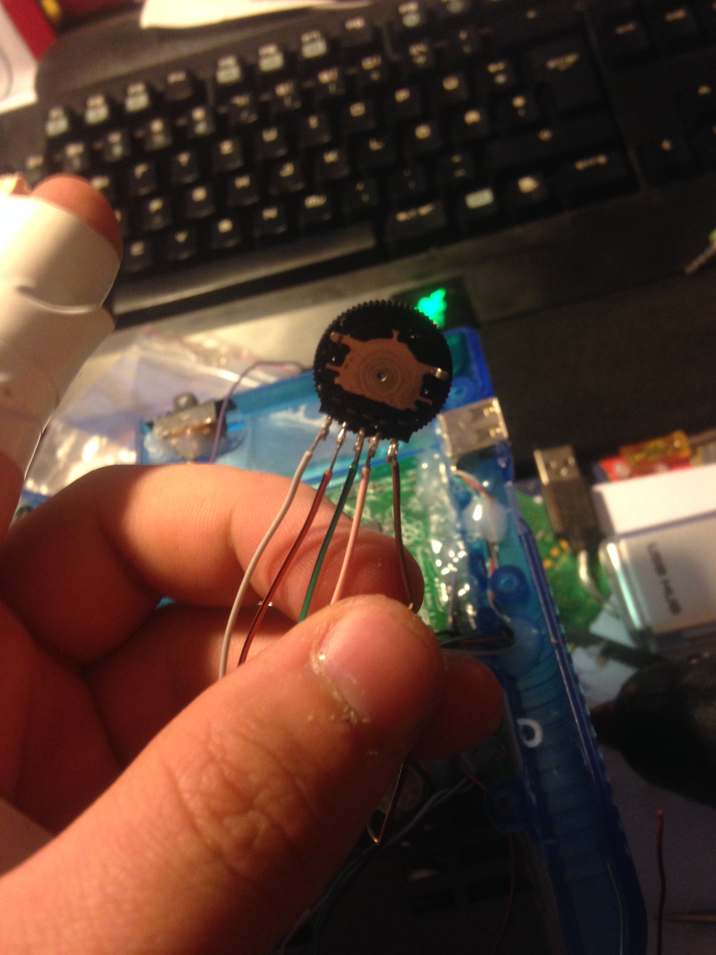
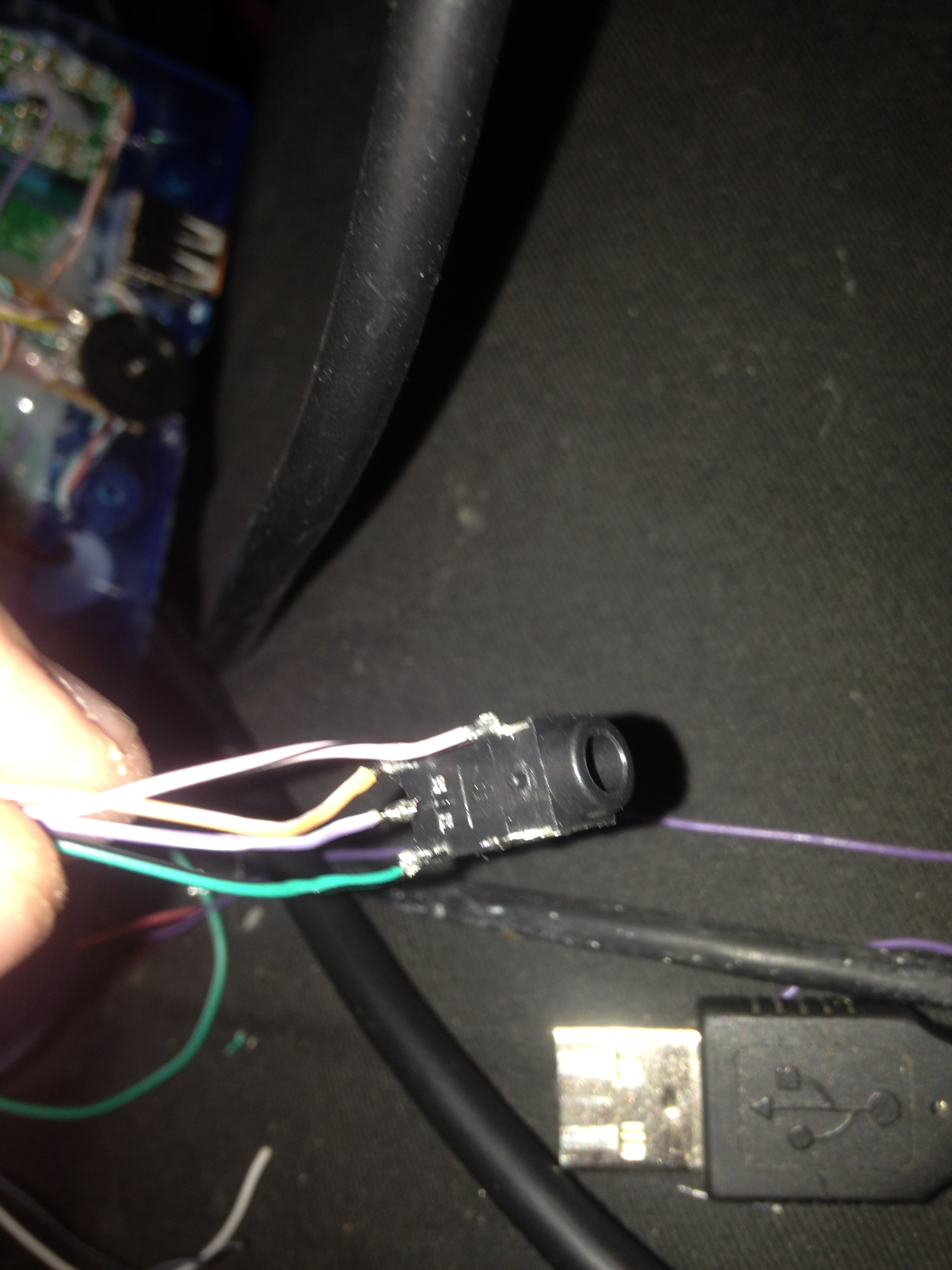
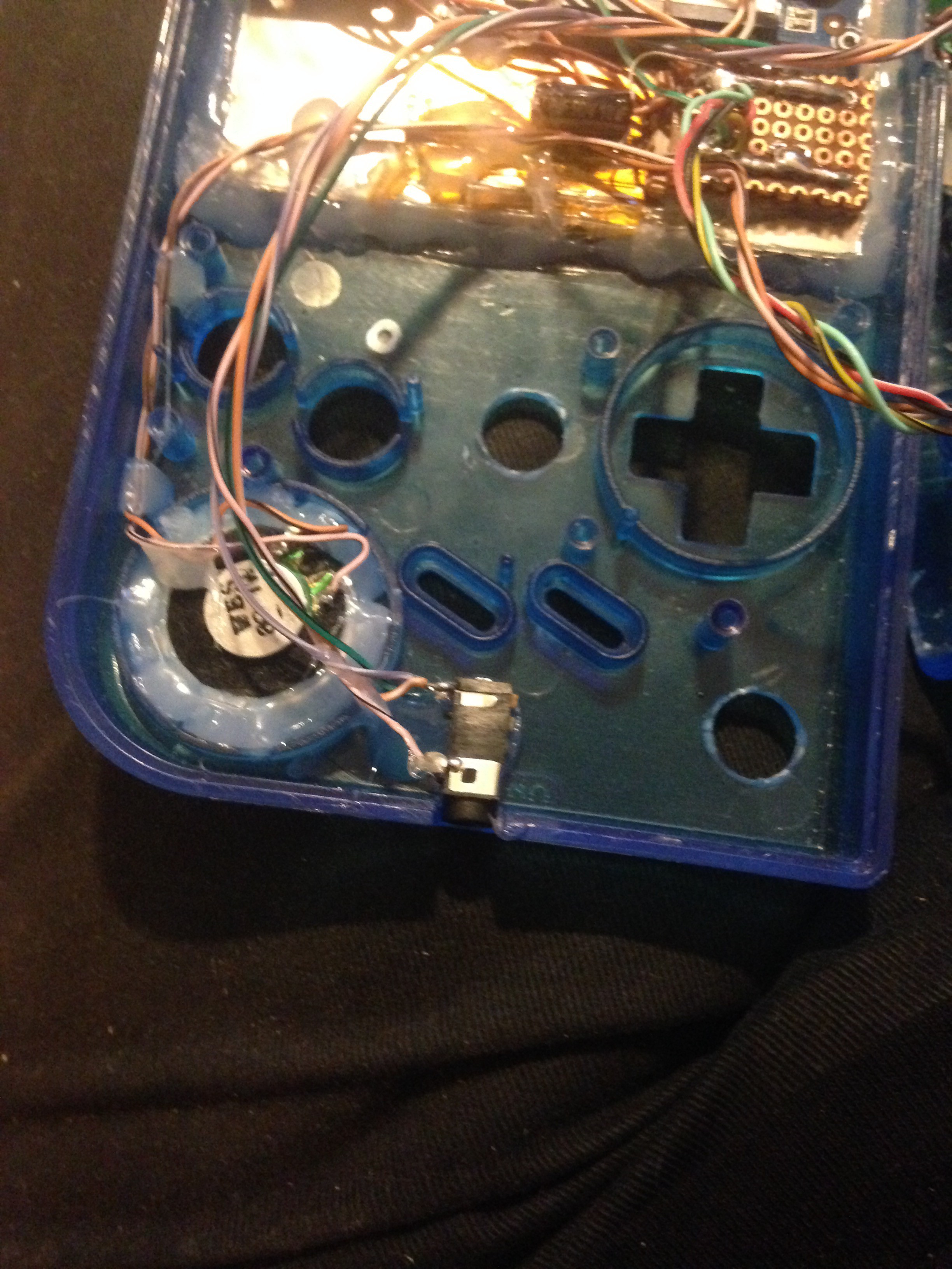
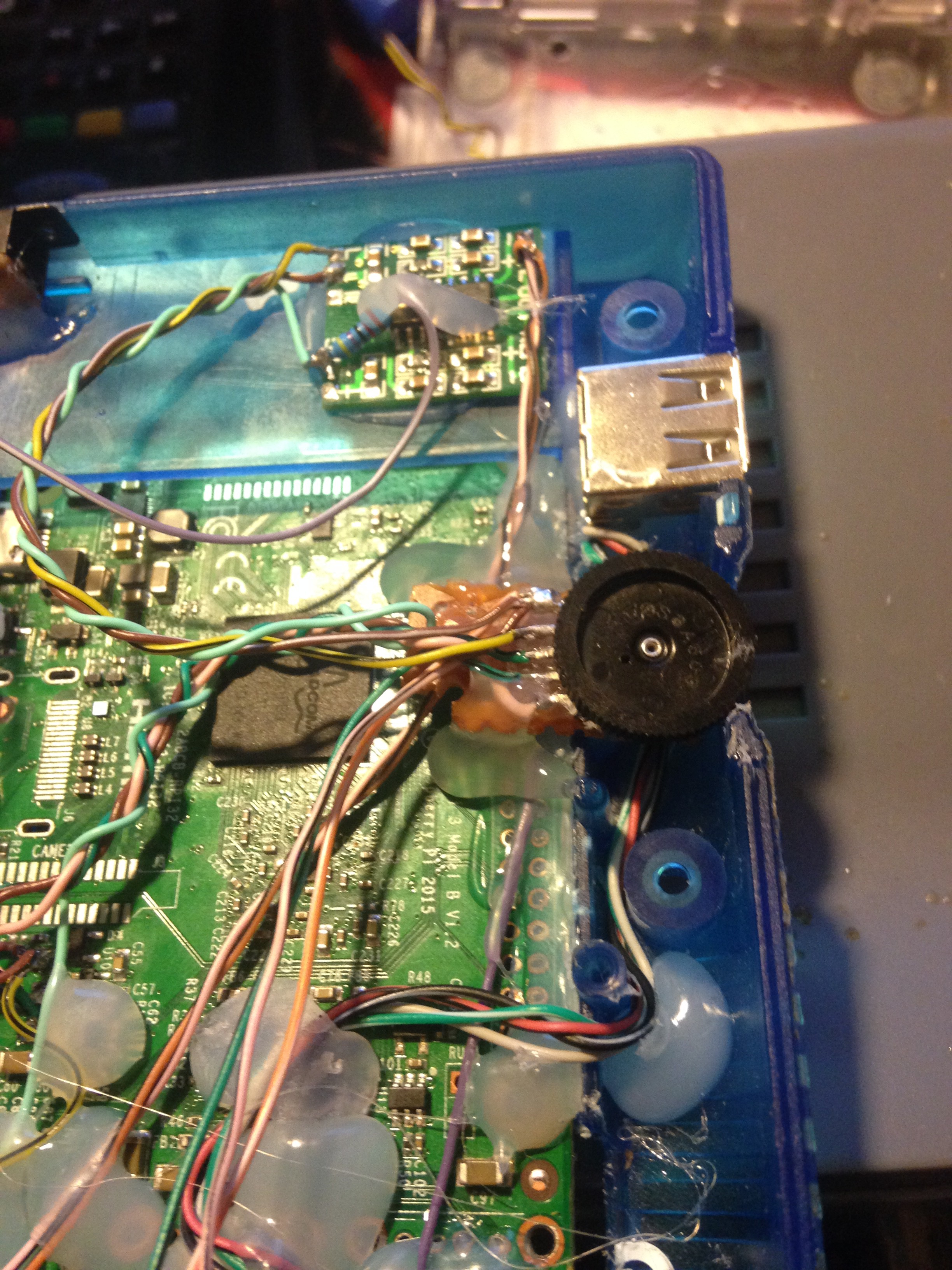
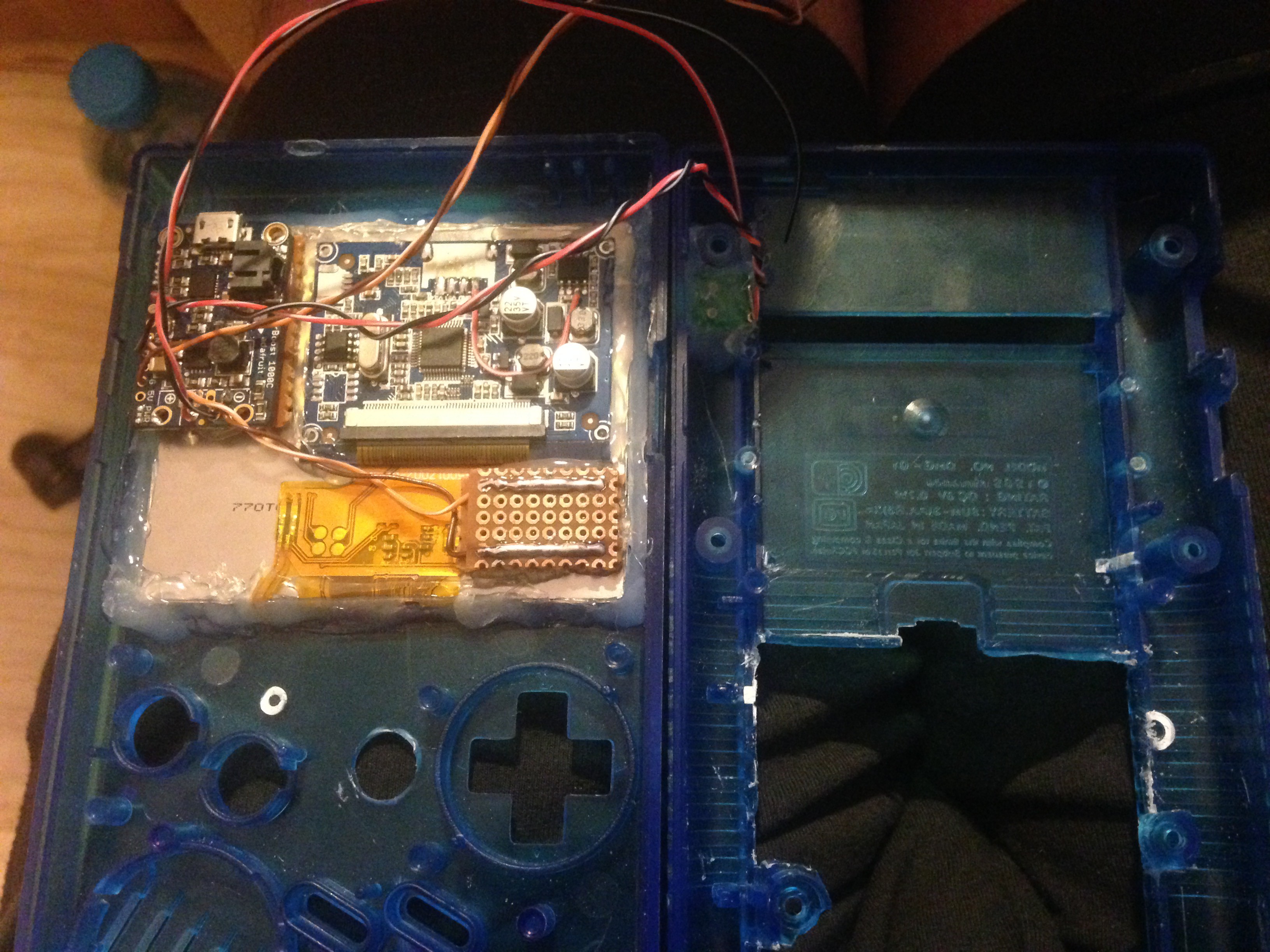
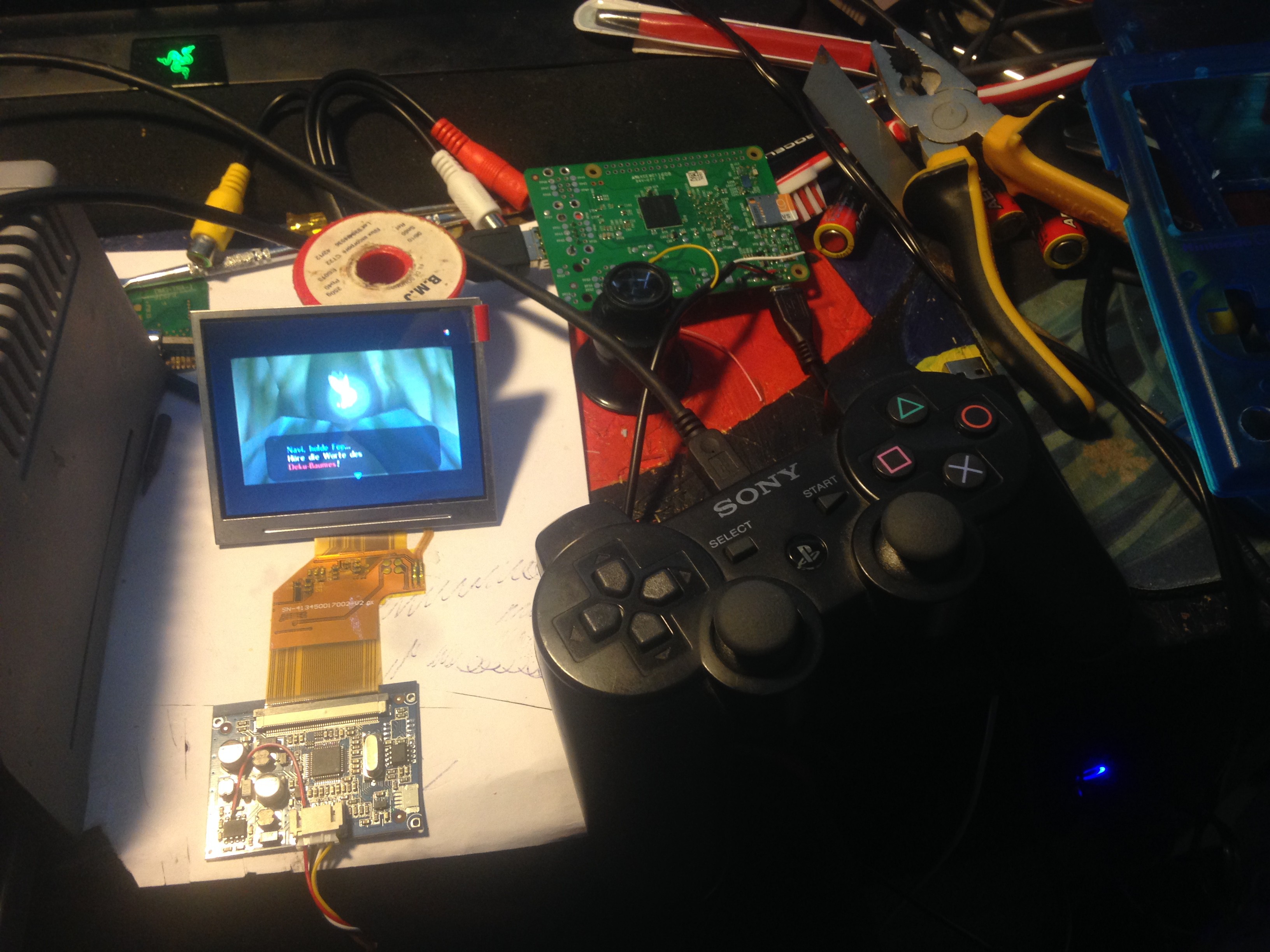
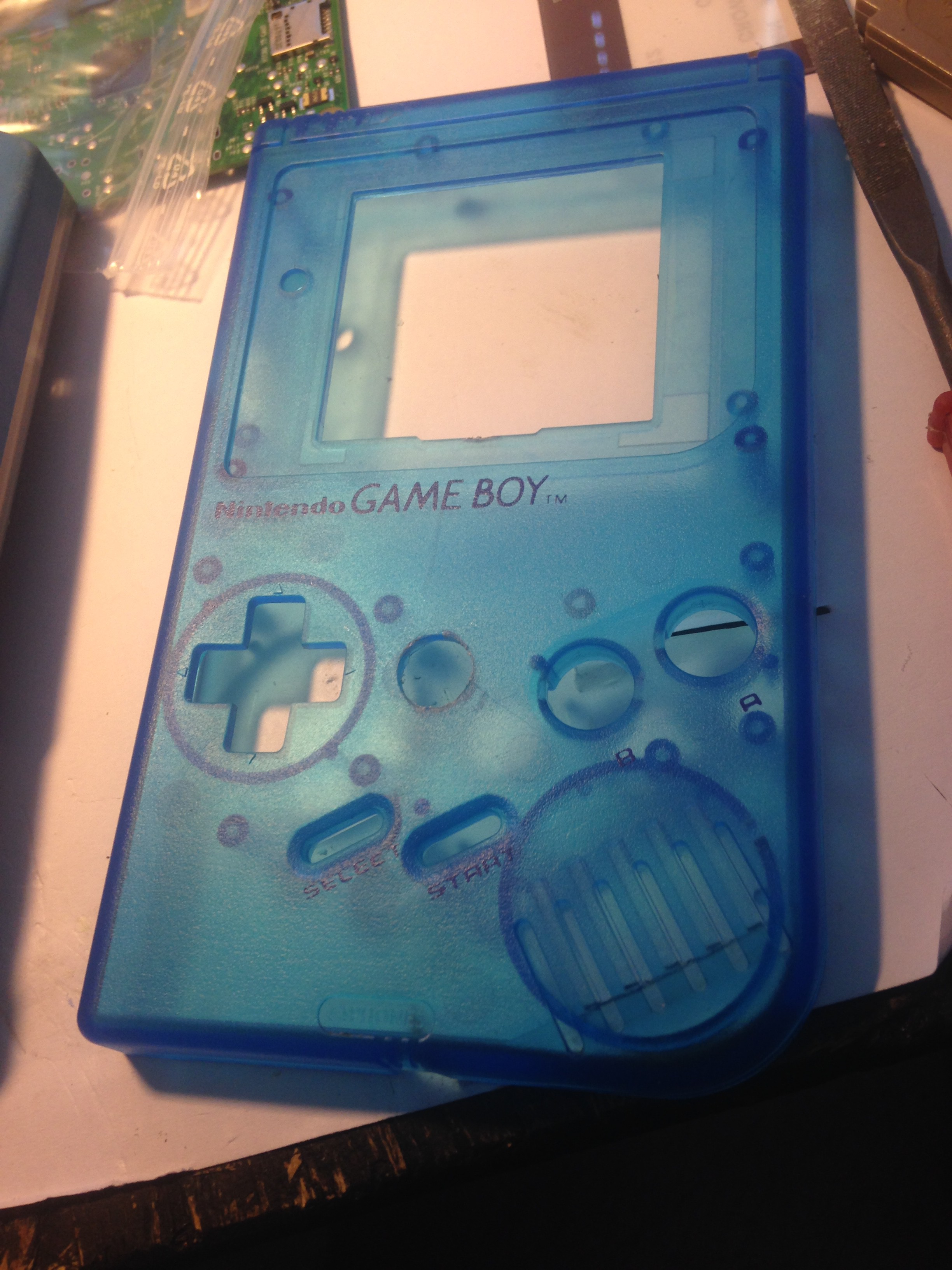
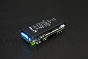
Then I thought about what parts I needed to get to make this project and made a little list of parts I need. Eventualy, I had my parts list and tried to find everything on eBay, which I did, except for a (grey or black) gameboy case like you see above, for some reason I only found the transparent ones here in germany, so I went with a blue one, which is also fine. After the parts arrived one by one, I started building. (You can follow the build log). The end result is an awesome, fun handheld gaming console able to play back so many memories from my childhood with games like the original NES and SNES Super Mario bros. series, doom, tony hawk's pro skater, the Final Fantasy series, Ocarina of Time, and of course alot more from alot of various gaming systems, just to name some. It features an 3.5" TFT composite screen, an sparkfun leonardo pro mico which acts as a gaming controller pcb, original gameboy buttons, 2 PSP 1000 analog sticks, L1, L2, R1 and R2 buttons, an Adafruit Powerboost 1000C USB boost and charging PCB along with a cellphone battery which has 3.7V and 2500 mAh. The front button PCB is a pre-made commercial PCB gotten hold of from a store named kitsch-bent, you can check it out here for alot of gameboy accessories and spare parts: Kitsch-bent's store. The speaker is a gameboy advance speaker which is a bit smaller than the original speaker supposed to go in there, but it fits just OK as well and it has more beef and is clearer as the original. It is driven with an amplifier based on an PAM8403 chip. To regulate the volume, I also used an aftermarket "Gameboy" style wheel potentiometer, which then goes directly to the raspberry pi's audio output. I also put in an additional arduino uno (just the atmega328 chip with an 16 MHz quartz) which monitors the battery. If it drops to a voltage of 3.54 Volts, an red LED will light up, so the user knows they have around 10-15 minutes of playtime before the battery drops to 3.20 Volts and the arduino then safe-shutdowns the raspberry pi via GPIO. There is a tactile switch on the upper right, which is connected to the same GPIO pin so that you also can (and should) safe-shutdown the raspberry pi when you want to stop playing for now. If the user decides to plug a charger in on the mini USB port, the shutdown of the arduino is surpressed of course....
Read more »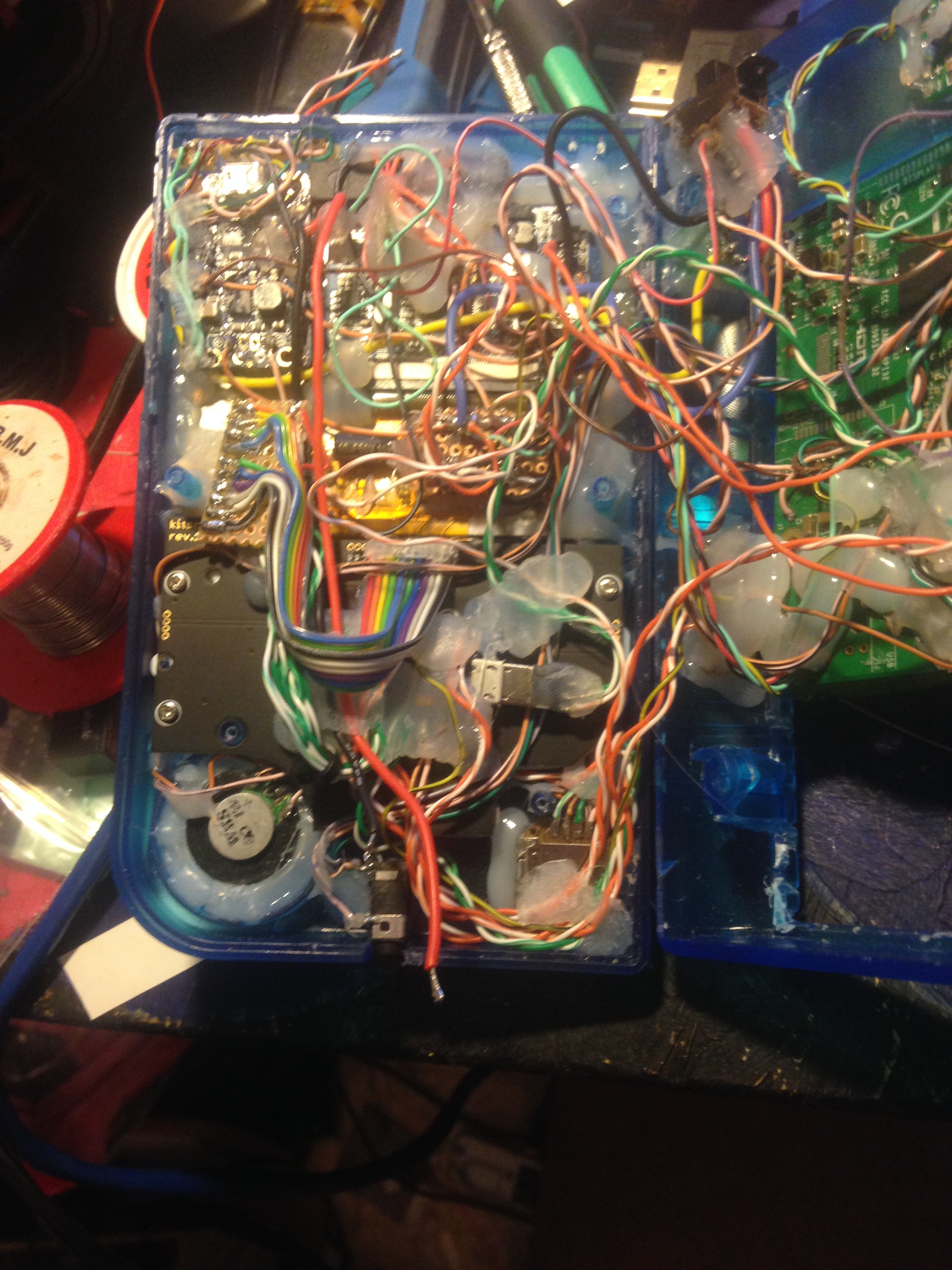


 Jdaie
Jdaie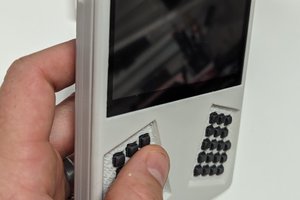
 Dan (a8ksh4)
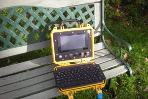
how long this device working in emulation ?