Close
0%
0%

The Big Flipper - Four Letter Word In Flipdots

What do you get if you mash up a word association database with some flipdot highway signs pulled out of a bin?

Similar projects worth following
Four letter word "clocks" have a venerable history as art objects. They used character displays to display seemingly random four letter words, originally generated randomly by custom electronics, then chosen according to a database of words that were chosen by participants in psychological trials when presented with a word, e.g DOOR might lead to OPEN or SHUT, etc. This project uses some old highways signs that were found in a bin. A goal was to make it look interesting.

The main project goal is to have a wall mounted display of 4 characters made from my old highway flipdot panels. Whats a flipdot? you can do worse than look at FredericL's project https://hackaday.io/project/159415. From my point of view they are an awesome obsolete display technology that is wonderfully mechanical and with superb sound effects when they operate. The operating principle of magnetic remanence, see https://en.wikipedia.org/wiki/Remanence is a beautiful example of physics in action, and also enabled https://en.wikipedia.org/wiki/Magnetic-core_memory!

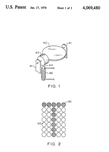
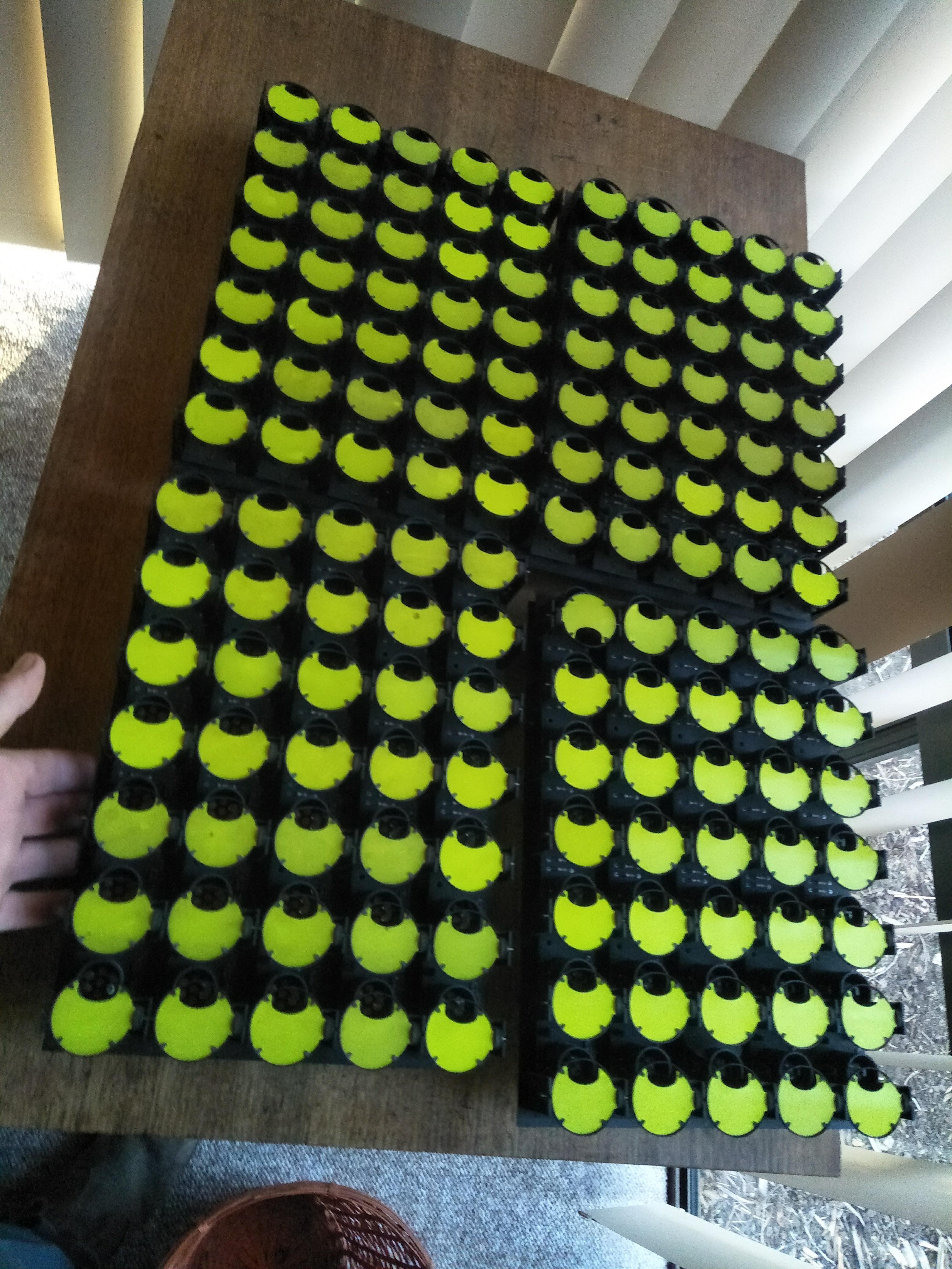
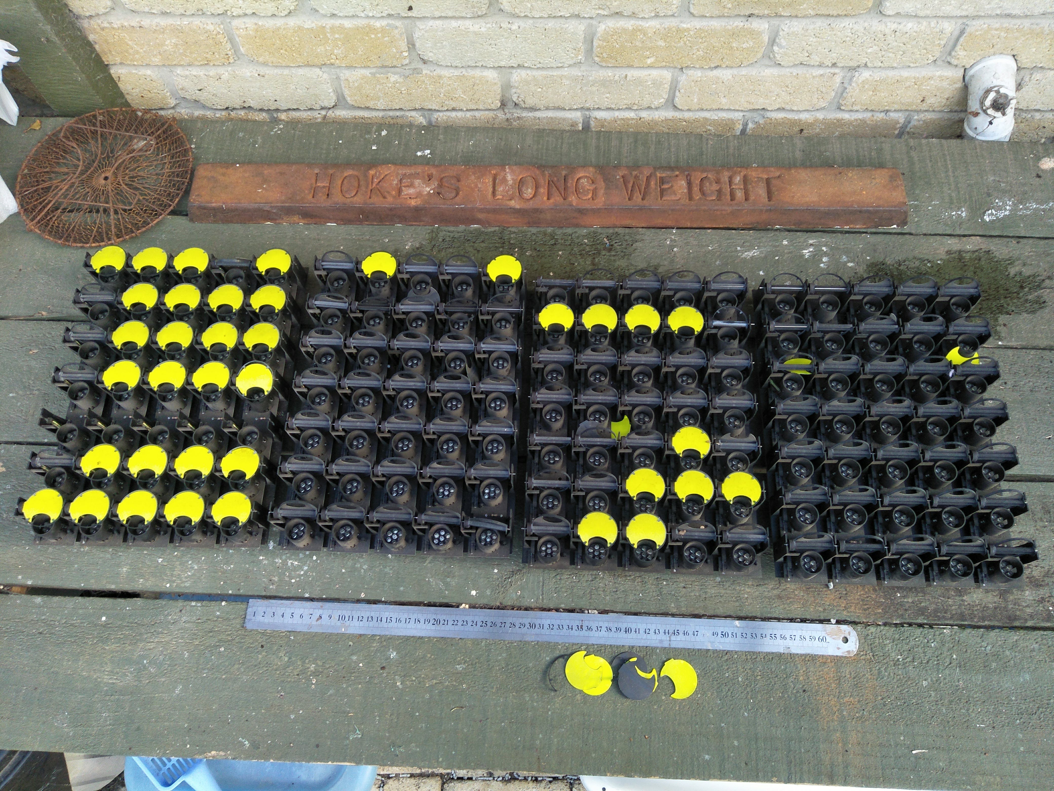
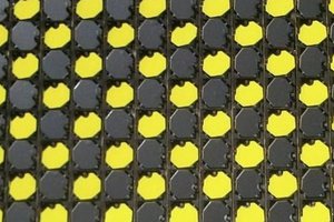
My panels are each 7 x 5 dots, and very large, about 240mm x 350mm, the dot size being about 38mm, so 1 1/2" in old money.

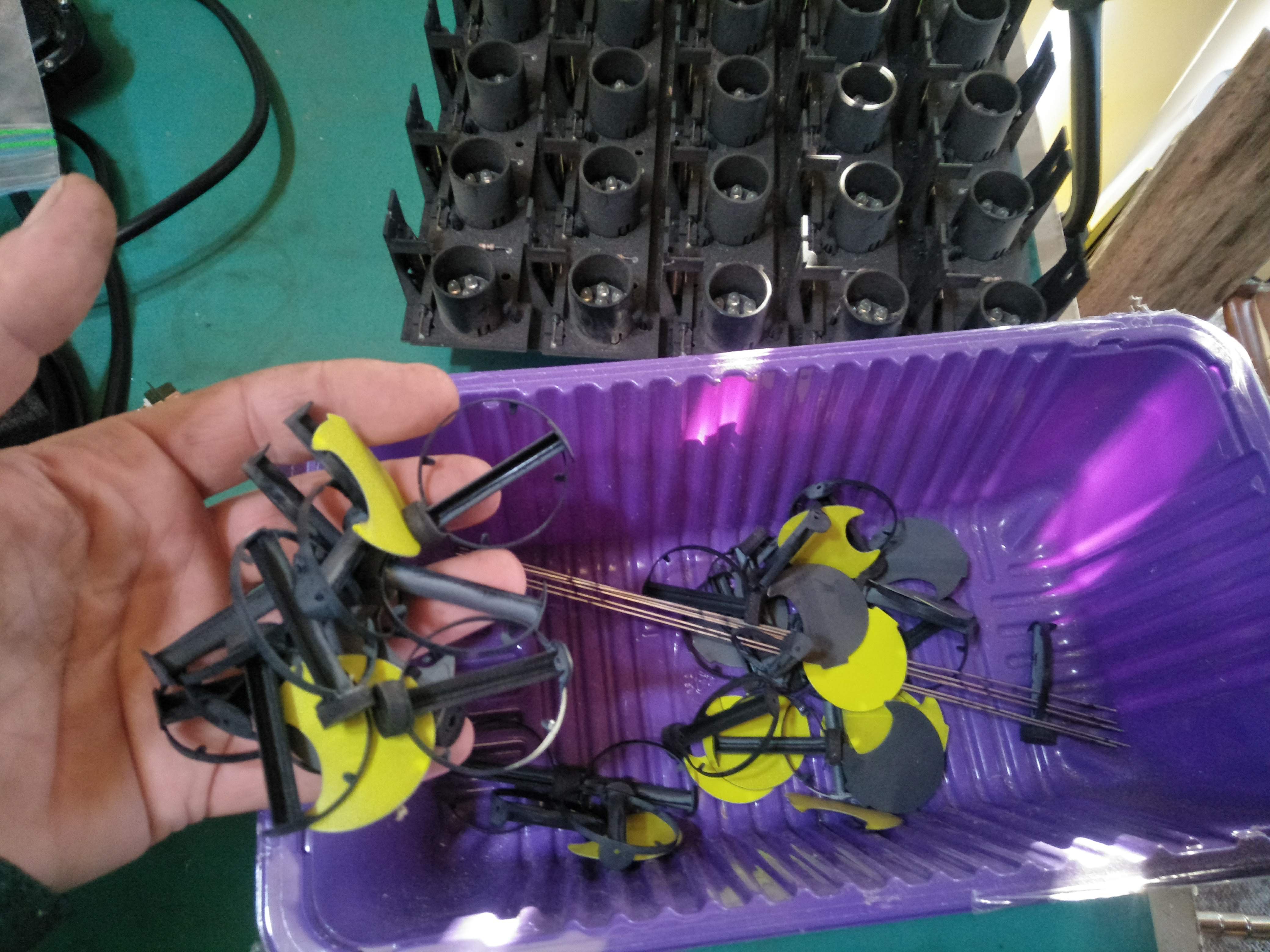
The panels were not in the best shape when I picked them up, and the 20 years that they have been in storage has not improved them. Luckily I have several boxes so I can mix and match parts to get 4 good panels.

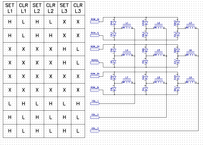
I did not find any driver electronics, but in 2015(!) did build an entire 4 panel driver board using motor driver ICs but it never worked so I shelved it. So I either have to resurrect it or build another driver.

Then I want to display seemingly random four letter words on the display chosen from a database of word associations. The original idea of the four letter word database I owe to akafugu, who sells the database as an addon for his VFD clocks: https://github.com/akafugu/FourLetterWord. I am not sure if he originated the concept of using the database, but I can't find an earlier example than his project punished in 2012.

I succeeded in my aim, I have a standalone display that will sit on the wall displaying random  associated four letter words. There is much left to do, the housing is made from a 50 year old packing case I cut up, and I need to score a large piece of acrylic to put on the front. I would also like to use a Raspberry Pi as the driver, then I can use real databases, display messages, etc.

But it works, and makes the most beautiful noises as it displays a new word.

Here's a haiku to celebrate:

the display updates,
magnetic domains realign:
rain on a tin roof

Acknowledgements

Akafugu for his four letter word add-on board here which gave me the idea of the associative word database. I think he may have come up with the idea of using the Edinburgh Associative Thesaurus as a source of four letter words.

Diptrace for giving me an upgraded license with a limit of 500 pins for drawing the schematic. I like Diptrace.

Hobart Hackerspace for encouragement and various components.

flw.pdf

Schematic for the driver. See the github repo for the Diptrace version.

Adobe Portable Document Format - 123.61 kB - 06/21/2021 at 22:52

Preview
Download

  • Drive Method

    Tom Harris06/21/2021 at 13:13 0 comments

    How I drive my Flipdots.

    Recall the previous project log where I described how to drive them. The column drivers require N drivers, of which one is set high/low and the remainder are set to the complement.

    In order to apply a pulse of current, we will say that the column drivers have to be enabled briefly to generate the pulse.

    The row drivers operate in pairs, one for each of the H & L lines for each row.

    My flipdots are 5 panels of 7 rows, each 5 columns, so a total of 7 rows by 20 columns. I decided to use the venerable L293 driver as I had several sticks left over from some project. These drivers are quad half bridges that are really intended for DC motors or two phases of a unipolar stepper, so whilst each half bridge can be driven high or low, the half bridges can only be enabled/disabled in pairs. But this is fine for the rows, as they operate in pairs anyway, and the columns are all enabled together.

    So the driver circuit consists of a lot of L293Ds (the 'D' suffix is important, the 'E' variety don't have catching diodes, so are not protected against the inductive kickback of the solenoids). A little ATMEGA328P (as used on the Arduino Uno & Pro Mini) microcontroller drives the row drivers directly, and the column drivers via some HC595 shift registers. The schematics are too large to include as images, but they are in the files section, and also on github. I use Diptrace for electronic CAD, but I have included pdfs as well.I built the driver years ago on dot board, but never got it working properly, so I threw it in a drawer and only resurrected it last month. The only docs were in a bare netlist format that I invented myself that is self-documenting, and some notes in an old sketckbook. Both are in the github. There is not that much interesting about the schematic, except: R2 pulls COL_EN to inactive when the pin is not set to output, like when the processor is being held in reset whilst being programmed by ISP or DebugWire. Else an internal pullup is activated that turns on the column drive, and was blowing drivers by turning on all columns at once! I haven't investigated different means of driving the solenoids, such as with a constant current source or a chopper drive, which decrease the turn on time to an inductive load. I just found that a 24V supply with a 12ω power resistor limits the current adequately. Certainly the 24V drive makes the dots flip faster than a 12V drive, as the current builds twice as quickly There really should be a hardware watchdog with a relay controlling the 24V power as a safeguard against the processor going crazy and leaving the drive enabled. The COL_EN signal connects to all the column driver enable inputs, and to the STCP inputs of the HC595 shift registers. It latches the data in the shift registers onto the output registers in the HC595 on the rising edge, and the high level enables the drive onto the column busses. This saves a pin on a tight design.

  • How I Drive the Flipdots

    Tom Harris06/21/2021 at 12:08 0 comments

    How They Work

    How they work is surprisingly easy. Each flipdot comprises a solenoid, a coil of wire wound round an iron core with specific magnetic properties. The actual dot is a vane that is pivoted so it either shows its brightly coloured face or moves 90Deg so that it is only visible side on. The vane has a small magnet on it, arranged so that one magnetic pole is close to the solenoid in one position, and the other pole close to the solenoid pole in the other; so that the magnet is actually a disk with 2 'N' poles and 2 'S' poles. Now remembering your school physics, that unlike magnetic poles attract, you can see that if the solenoid pole is of one polarity the flipdot will show it's bright face, and of the other polarity it will turn 90Deg and be nearly invisible.

    Here's a page from the patent by Ferranti packard / Mark IV Industries fro my flipdots that shows the maechanical arrangement nicely. It's online <a href='https://patents.google.com/patent/US4069480A/en'>here</a>.

    And now magic happens: by making the solenoid core out of an iron that can maintain its magnetic polarity after the current in its windings have stopped flowing each disk now remembers its position. Look up 'magnetic remanence' for more on this fascinating phenomemon, which also enable core memory to function. Typically a pulse of a few hundres microseconds is sufficient to reverse the magnetic polarity of the core. Of course the actual disc requires a bit longer to actually move.

    How to Drive Them

    It's actually quite hard to get your head around how to drive these flippin' things. The end requirement is to be able to pass current through exactly one coil, without affecting any others, and to use the absolute minimum number of components.

    Firstly you have to understand how they are wired up, see the next schematic. This scheme is used on evey panel I have ever seen, Wikipedia claims that some panels were wired up in a simple matrix without diode, but I have never been able to get this to work.

    Anyway, looking at the schematic, you can see that each columns are commoned to one bus per column, but each row is connected via a pair of diode to two busses per row. The schematic shows a very small panel of 9 flipdots, so it has 3 column busses (COL_1 through COL_3) and 6 row busses ('ROW_[1-3]H' & 'ROW_[1-3]L'. The principle of operation can be extended to panels of any size.

    Driving Principle

    First some circuit analysis principles: remember that the solenoids are actuated by current flow. If both ends of the solenoid are at the same voltage then no current can flow. Also remember that current can only flow one way through a diode. We specify that if current flows from the solenoid terminal with a · to the other terminal then it will 'set' and become visible. Current flowing the other way will 'clear' it so that it becomes non-visible.

    In these schematics and those following the rows and column busses are driven by tri-state drivers, so they can be actively driven high 'H' or low 'L', or they can be undriven, denoted 'X'. In the schematic below there are 9 flipdots with a table showing how each bus line is driven to give a specific result. Each column of the table shows how to drive the busses to set or clear a single flipdot.

    The first column (of the table!) sets the top LH flipdot 'L1' by driving both ROW_1H & ROW_1L high ('H'), with all other rows undriven ('X'). For the column drives, COL_1 is set low with the other columns set high.

    Lets analyse how this works. For the rows, since none of the diodes on the ROW_1L bus are forward biased, how can they be, the cathodes are driven to the high voltage in the system, so they do not conduct, so can be ignored. Now the other row buses ROW_2L through ROW_3H are all undriven, so the buses are floating, and will take on whatever voltage is on the column end of the solenoid. But every column drive apart from COL_1 is driven high so no more than 1 diode will be forward biased, all the...

    Read more »

  • Flipping!

    Tom Harris06/18/2021 at 06:54 0 comments

    This is out of sequence but I have been on a roll getting the driver electronics going and chasing hardware problems that caused driver chips to meltdown!

    Here's a video of The Big Flipper running a simple test pattern:

    And here's one of it streaming words fairly fast, actually about half the maximum update rate.

    Sorry about the poor quality and the  mess in the workroom but these are in the nature of an interim update. And I suppose I should give back the ironing board.

  • Panels all fixed up

    Tom Harris06/07/2021 at 22:16 0 comments

    I managed to get 4 complete working panels. Many of the small plastic holders for the dots have broken, they are amazingly delicate. I imagine that once installed and out of the weather they would have been reliable enough. As I mentioned previously every dot worked fine once it was mechanically whole again. I suppose with solenoids and diodes there's not much to go wrong.

    Note to self: always set all dots to visible, so that they are horizontal. They are less likely to get damaged.

    What a beautiful sight, 4 working panels.

    An entire panel's worth of broken dots. Most are fixable if I find some glue that will work. But I could 3D print replacements I suppose.

  • Making the Flippin' Thing Flip

    Tom Harris05/28/2021 at 11:41 0 comments

    I should say how to make a panel flip. If you look at FredericL's project https://hackaday.io/project/159415/ and watch Lansing Maker's Network excellent video on the Flipmaster9000(!) on Youtube then you will know all about how they flip.

    So you will see that they are wired in a matrix of one column connection, and two connections for each row, which I call H & L. Current will only flow into the H row connection (so positive DC to H, negative to common), or flow out of the L connection (so negative DC to H, positive to common).

    I now had to identify the row and column connections. On the back of the panel are a 40 way header marked COLUMNS and a 34 way marked ROWS. I did some continuity tests and noted that the column pins are commoned 1 through 8, 9 through 16, up to 32 through 40. Pins 1 &2, 3 & 4, etc are commoned on the row pins. Now I set a bench power supply to 30V, current limit 250mA and started poking current through the panel. I guessed that this current could not damage the panel provided that I did not keep it connected for longer than a fraction of a second.

    What I found surprised me, neither the rows or columns are in sequence. Probably this was done as the PCB for the panel is single sided, so the designer didn't want any wire links. Also the row L connections set (dot visible) some rows, and clear (hide dot) others. Again this must have been done to make the PCB easy. But it complicates the driving, at least as it will be done in firmware that will be easy.

    Anyway, here's a table of connections. Columns are numbered from the left 1..5 and rows numbered down 1..7.

    1..8: C2

    9..16: C1

    17..24: C3

    25..32: C4

    32..40: C5

    1, 2: R7L (clear)

    3,4: N/C

    5, 6: R7L (set)

    7, 8: R6L (set)

    9, 10: R6H (clear)

    11, 12: R5L (clear)

    13, 14: R5H (set)

    15, 16: R4L (set)

    17, 18: R4H (clear)

    19, 20: R1H (set)

    21, 22: N/C

    23, 24: R1L (clear)

    25, 26: R2H (clear)

    27, 28: R2L (set)

    29, 30: R3H (set)

    31, 32: R3L (clear)

    33, 34: N/C

    An example: to set dot on row 3, column 2: positive on R3H, negative on C2. To clear it, negative on R3L, positive on C2.

  • Fixing a Flipdot Panel...

    Tom Harris05/28/2021 at 11:00 0 comments

    I took one panel and had a good look at it. As can be seen, there are quite a few breakages.

    These need fixing else the yellow dot will fall out as it will not be secured properly. I tried gluing them with superglue, but it did not work well on the plastic, which is some sort of very brittle glass filled stuff. I suspect that it will need epoxy glue to do a proper job, so I'll do a whole batch at once to avoid wasting glue.

    So I selected the most beat up of my five panels as a donor and started taking it apart. The rows of dots rotate on a thin steel wire, which can be carefully removed by pulling with pliers. Like so:

    And then I ended up with this. All 35 dots are in one piece and rotate freely. Now to check if they actually work. I did this last as I have never found an electrical fault with these panels, somehow they are super reliable.

  • Grabbed the flipdot panels from the shed.

    Tom Harris05/28/2021 at 10:37 0 comments

    The answer's in the shed, now what's the question?

    I started this project by a happy coincidence: I was looking though my store of *stuff* and found several boxes of flipdots that I scored when I was working next to a highway sign maintenance company; and I read on Hackaday that they had a contest involving retro technology.

    So I pulled out one box of flipdots. Unopened since 2015.

    In here were 5 flipdot panels, each 5 x 7 pixels. Here's a photo of 4 of them arranged so as to give an idea of the final clock. The ruler is 600mm. Please ignore the photobomb from my Hoke's Long Weight, the object that many apprentices have been sent to ask for but somehow is never in stock...

    As you can see many of the disks have become loose, due to the plastic carriers getting broken, they really are very delicate.  Tonight's job is to get one panel in good order so that I can document how it works and how it is connected.

View all 7 project logs

Enjoy this project?

Share

Discussions

Similar Projects

Does this project spark your interest?

Become a member to follow this project and never miss any updates