Jianjia Ma
About this project
The goal is to build a small and versatile weather station. But before introducing this project, I shall mention my other project DeepPlankter. DeepPlankter is a tiny autonomous water drone ship that could sail in the ocean for months using wave-propelled underwater wings. Sailing alone is fun though, if we can collect some meaningful data during the sailing will be even more exciting.
Thus, a weather station is perfect to fit this purpose! Imagine that the ship is measuring wind velocity on a 10 metres high wave at the centre of a storm. So challenging.
There are some goals of the weather station:
- Low-power
The electronics on the ship is supplied by solar panels so is the weather station.
The solar panels have a peak power rating of 10W, or 40Wh in a sunny summer day.
However, this 10W will need to supply the main controller, GPS, satellite, rudder servos, and charge batteries for over-nights supplies.
A rough estimation is <100mA average current for the whole ship.
The weather station should have a maximum 10mA average current.
- Small & lightweight
The drone is small, with a deck width of only ~12cm.
Ideally, the dimensions of the weather station should be less than the width of the deck.
When installing it on the ship, it should be placed as high as possible.
Elevating a large mass on the mast decreases the stability of the ship.
- Versatile
While keeping it small, implement as many digital sensors as possible.
There are 2 DIY analogue sensors, the ultrasonic anemometer and infrared rain sensor onboard.
Repositories
- Hardware: please see the PCB folder in the main repo.
- Firmware: QingStation-Firmware
- Bootloader: QingStation-Bootloader
Features and functions
For the hardware V1.1
Features:
- MCU: STM32L476RG
- PCB dimension: Φ48 mm
- SDCard
- RTC
Sensor Integration:
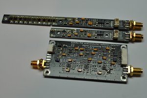
- Anemometer (2x2 Ultrasonic transducer array
40k/200kHz) - Rain sensor (IR Optical type)
- Lighting sensor (AS3935)
- IMU & eCampass (BMX160)
- RGBI light sensor (APDS-9250)
- Microphone (MP34DT05/6)
- Barometer, humidity, temperature sensor (BME280)
Communication Interfaces:
- 2x UART
- I2C
- SPI
- CAN (FDCAN)
- USB (CDC and/or MassStorage)
Power Consumption
- Normal 20~22mA
- Normal + GNSS: ~45mA
- Normal + GNSS + ESP8266(MQTT @ 1Hz): ~100mA
- Sleep: unknown
External Communication
- ESP8266 (AT)
- ESP32 (AT)
- SIM800c
Functions description
Digital sensors are used whenever it is available. Today's digital sensors are easy to use as long as they are connected to I2C correctly. The onboard sensors were all up in a day.
Analog sensor
The rain sensor is consist of a pair of an IR transmitter and a receiver. The method is to use the reflection of a piece of trapezoid glass (hand made..). When droplets land on the surfaces of glass, it will reduce the reflection, therefore the signal magnitude on the receiver will change. We can either use calibrated absolute value or use the covariance. This sensor will not be accurate. Even when on the sea, droplets from large waves can easily keep the sensor wet all the time.
Ultrasonic Anemometer is the most difficult sensor but also the most challenging sensor. The anemometer uses a reflection of the ultrasonic beam to measure the speed of air in 2 horizontal direction..ideally. The reality is much complicated, it well worth a separate document. A good project by Hardy Lau mentioned most of the principle and information.
One of the advantages of the ultrasonic anemometer is it needs NO MOVING PARTs to measure wind speed and wind direction.
Digital sensor
For the lighting sensor (AS3935), I could not make an easy test to validate my antenna design.
For the RGBIR sensor, we cannot calibrate the sensor using a cosine corrector which the light sensor usually used. I have no tools that can calibrate this sensor. RGBI sensor can provide colour data than a single lumen meter.
IMU and eCampass are not needed for a stationary mounted weather station. But in sailing, its high mounted location is perfect for navigation...
Read more »


 Andrew Ferguson
 agp.cooper
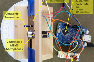
 Filip Mulier