Close
0%
0%

Gesture/Pattern Recognition Without Camera : TOF !

Grumpy Hedgehog is a connected device that allows you to read and interact with movements. Its LCD screen displays the Hedgehog's expression

Similar projects worth following
The system is based on low cost TOF sensors with "Multi-zone scanning with selectable array" allowing each to behave like a 16 or 64 pixels TOF camera at a distance between 1 and 300" (60Hz/pixels).

By multiplying the number of TOF (only 9$ each!) on the same I2C bus, we can improve the speed and resolution. This allows to use a low cost camera completely adaptable to the requirements.

With 3 sensors (16 pixels each) on the bus :
> We can get the whole sensor view at 150Hz
> Focus on 3 opposite areas to detect 4 fast movements "left/right/up/down" at 50Hz
> By playing with angles between the sensors, create an adaptable Grid 4x12 pixels, FOV 87°

We can easily create our own movements and patterns to transmit actions through several communication channels (USB HID, Wifi, IR...) or simply use its relay and servomotor.

In order to facilitate the interaction, a 240x240 pixels screen displaying the character's expressions or a dete

1.1 What issues will this solve?

Today we are used to have physical contact with the objects that surround us. This applies to switches, touchscreens, remote controls... The current crisis forces us to question these habits and to enter a new digital era where physical contact with certain objects must be reduced to a minimum.

While speech recognition allows a complete approach for transmitting information, it is still quite complex for machines and humans to grasp. A child is usually able to understand and imitate many signs long before his or her first words.

Why not use signs to create simple interactions that can convey more information than ON/OFF?

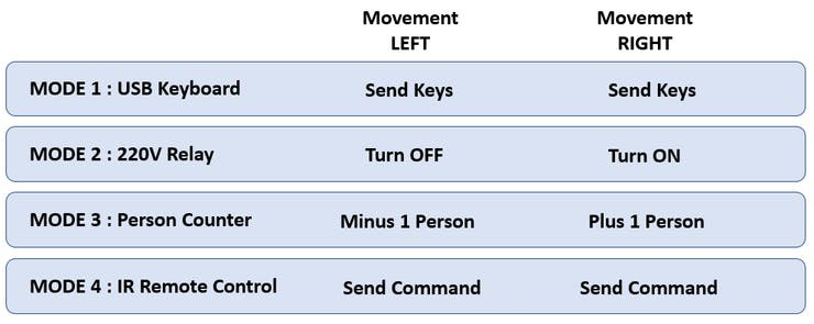
Once you send a movement or a pattern, GrumpyHedgehog can :

  • Control a computer by sending keyboard command (movie pause, volume...)
  • Track the number of person in a shop on your smartphone
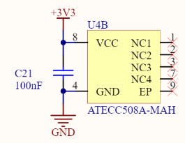
  • Safely unlock a computer
  • Send encrypted informations to a server
  • Control light or any power components
  • Send IR command to your TV
  • Move a servo motor

1.2 Key Elements

In addition to offering a modular solution with different interfaces Grumpy Hedgehog is particularly distinguished in 4 aspects:

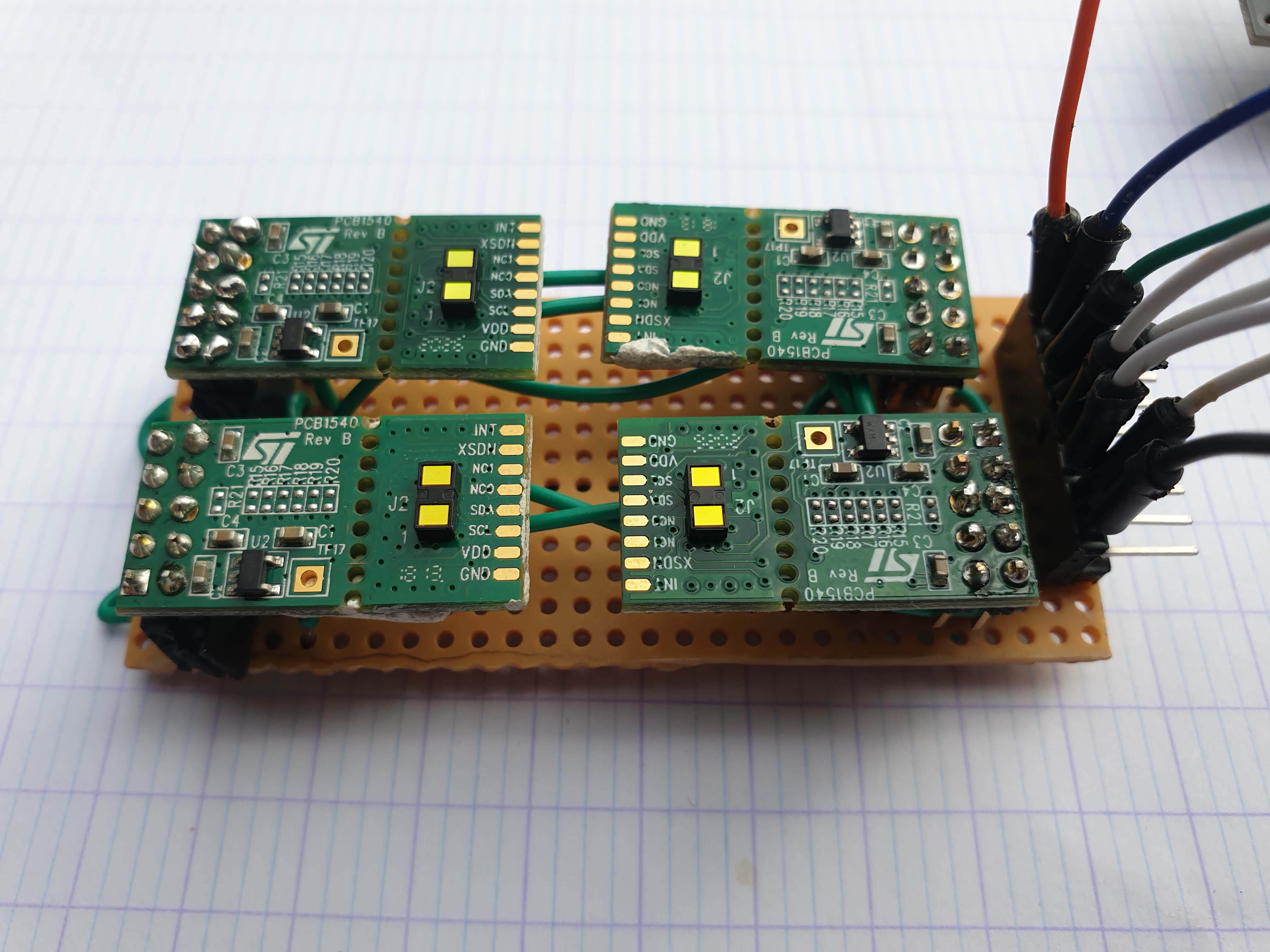
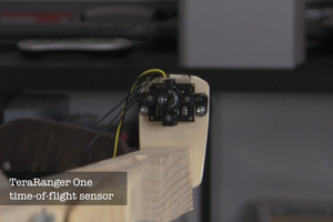
  • It uses VL53L1X Time Of Flight Sensors allowing complex motion recognition with 16x16 SPAD sensing array, it can run on any 8 or 32 bits micro-controllers with I2C capability such as Teensy3.2, SAMD21 (MKR Wifi 1010),  Atmega328p (NANO/UNO board)...
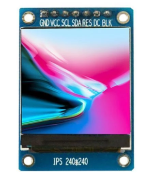
  • The second aspect is the management of the LCD screen which is optimized to avoid to store in FLASH and display a moving image using GFX libraries. This part is really important, because it allows an Arduino Uno at 16Mhz to display a moving image. But the code was also tested on a Teensy 3.6 in order to use SD storage for complex video sequences.
  • The third differentiating aspect is its design. The challenge here is to create a decorative object that you will happily have on display in your living room or office.

Thanks to this, the GrumpyHedgehog with his thirst for learning, his gestural communication, his attractive design and his grumpy character will quickly become your favorite new companion.

Gerber_PCB_Test_1_2021-11-07.zip

Gerber file for PCB LCD/TOF

x-zip-compressed - 5.83 kB - 11/07/2021 at 21:59

Download

Angle_tool.skp

Little tool to help soldering header with angle

SSEYO Koan Play File - 143.93 kB - 11/07/2021 at 20:49

Download

Relay_Servo_HH_box.skp

Sketchup Box file to integrate relay and servo

SSEYO Koan Play File - 233.15 kB - 10/31/2021 at 13:03

Download

HedgeHog_Main_3D.skp

Main sketchup file including all object to print the Hedgehog

SSEYO Koan Play File - 289.05 kB - 10/31/2021 at 13:03

Download

  • 1 × Teensy 3.2 (other platform possible)
  • 1 × VL53L1X ST TOF (One.. or as much as you need !)
  • 1 × TFT LCD 1.44 (128x128 of 240x240)
  • 1 × Single Relay
  • 1 × SB90 Micro servo Motor RF, RFID Hardware / Antennas

View all 11 components

  • [TOF] Detection now running at 150Hz with 3 sensors

    jean.perardel11/08/2021 at 10:43 0 comments

    By integrating the Start Ranging and the Check on separate loops. The code can now run at full speed. 
    This allows us to reach 110Hz with 2 sensors, 150Hz with 3, 200 Hz with 4. 

    int detect_All() {
      int range = 250;
      int distanceAll = MAX_DISTANCE_SHORT_DETECTION;
      for (int i = 0; i < NUMBER_OF_TOF_SENSORS; i++)
      {
        distanceSensor[i].setROI(16, 16, 198);
        distanceSensor[i].startRanging(); //Write configuration bytes to initiate measurement
      }
      for (int i = 0; i < NUMBER_OF_TOF_SENSORS; i++)
      {
        while (!distanceSensor[i].checkForDataReady()) {
          delay(1);
        }
        distanceAll = distanceSensor[i].getDistance(); //Get the result of the measurement from the sensor
        if (distanceAll >= MAX_DISTANCE_SHORT_DETECTION) {
          distanceAll = MAX_DISTANCE_SHORT_DETECTION;
        }
        distanceSensor[i].clearInterrupt();
        distanceSensor[i].stopRanging();
    
        if (distanceAll < range) {
          return 1;
        }
      }
      return 0;
    }

  • [CODE] Compatibility with Atmega328p

    jean.perardel11/08/2021 at 09:57 0 comments

    I just finished porting the code to run on an Atmega328p. This means that we can now use standard Arduino boards (UNO, Nano, Leonardo...) 

    For a question of integration in the box, I rather recommend using the NANO board. 

    #if defined(TEENSYDUINO)
    #define TOF_SDA 18
    #define TOF_SCL 19
    #define VL53L1X_1 17
    #define VL53L1X_2 16
    #define VL53L1X_3 15
    #define VL53L1X_4 14
    
    #elif defined(ARDUINO_SAMD_MKRWIFI1010)
    #define TOF_SDA 8
    #define TOF_SCL 9
    #define VL53L1X_1 7
    #define VL53L1X_2 6
    #define VL53L1X_3 5
    #define VL53L1X_4 4
    
    // #Arduino UNO, NANO, Leonardo...
    #else 
    #define TOF_SDA A4
    #define TOF_SCL A5
    #define VL53L1X_1 A0
    #define VL53L1X_2 A1
    #define VL53L1X_3 A2
    #define VL53L1X_4 A3
    #endif

  • Arduino Code : Board management

    jean.perardel11/07/2021 at 22:16 0 comments

    Making a generic project allows a maximum of people to reproduce it. That's why I tried to make it compatible with all kind of controllers, even the less powerful ones. 

    But I also use some specificities, only present on some controllers to bring more functionality to my project (USB-HID on Teensy, Wifi or Secure Element on MKR 1010). 

    To manage several boards in his Arduino project without having compilation problems, I used lines like this 

    #ifdef ARDUINO_SAMD_MKRWIFI1010
      #include <WiFiNINA.h>
      #include <BlynkSimpleWiFiNINA.h>
    #endif

    This will allow to include this library, only if I compile with a MKR 1010 target. 

    To manage features like USB HID, I now use this kind of code :

      #ifdef USB_SERIAL
        Serial.println("PASSWORD");
      #endif
      #ifdef USB_HID
        Keyboard.print("PASSWORD");
      #endif

  • New algorithm for LCD moving object

    jean.perardel11/07/2021 at 22:04 0 comments

    With my first algorithm, to move the circles of the eyes or the nose, I would redraw the previous shape in black and then I redraw it with color to its new position. This is a very simple way, but it make the screen a bit blinky...

    From GFX Library, to move a "fillCircle()" in a direction, I used a hidden function called "drawCircleHelper()" to remove only a part of the border circle. 

  • PCB Gerber available

    jean.perardel11/07/2021 at 21:58 0 comments

    I just finished the PCBs for the LCD/TOF interface board. The Gerber will be integrated in the repo


  • A simple 3D printed tool to position the connector at 15 degrees

    jean.perardel11/07/2021 at 20:43 0 comments

    The sources are on the project repo

  • Add a secure element ATECC508

    jean.perardel11/07/2021 at 19:29 0 comments

    In order to protect its data, the Arduino MKR 1010 implements an ATECC508. With a good implementation, this small device allows the integration of almost infallible security in the communication.

    After some research, I found 2 Arduino libraries (ArduinoECCX08 and Sparkfun) allowing to integrate some functions of the ATECC508. WARNING: the configuration of the device is permanent. If you accept the default configuration of these libraries, you will never be able to change it again.

    There are many ways to use this module, but these libraries focus on generating Public/Private key pairs and certificates to ensure the integrity of messages. There are already several tutorials to use these functions, I tested this one which worked well to connect to Google Cloud IOT with my Arduino MRK 1010. There is also this example to connect to Azure IOT Hub (but I didn't test it on MKR).

    In our case, we would like to use ATECC508 to store private information (a pattern and a password). The SAMD21 would have to send Patterns to it and the ATECC508 would have to compare them with the one in memory. If this one matches, ATECC508 will send the password. (This part isn't finished yet !)

    To integrate this, you must already understand the notion of configuration. Fortunately, the ATECC508 Datasheet is available on the internet (which is not the case for all secure elements, check for the complete datasheet with 109 pages). What we need is to set the correct configuration in "SlotConfig" (Section 2.2.1 SlotConfig (Bytes 20 to 51)) to enable "CheckMac" command (See section 3.2.7 Password Checking).

    To use Password checking we need to configure ReadKey in the target SLOT to 0 (bit 3-0 of SlotConfig). This enable "CheckMac/Copy". If we check the default configuration of ArduinoECCX08 we have :

    SLOT<0> : 0x83, 0x20, // External Signatures | Internal Signatures | IsSecret | Write Configure Never. This mean we have 0011 (0x3) as ReadKey instead of 0. So we need to configure a Slot with 0xX0, 0xXX

    On datasheet we have "If the password is to be mapped to a secondary value (using the third option above), then the target slot containing this value is located in the next higher slot number (i.e. the password’s slot number plus one);"

    So we can use

    • SLOT<8> with 0x80, 0x00 to store the patern
    • SLOT<9> with 0x80, 0x00 to store the secret password

    I will not have time to test this part before the contest deadline. So I will finish this article after the contest.

    The SAMD21 and the ATECC508 communicate with SPI on PA8 (SDA) and PA9 (SCL) or with One Wire with PA8 (SDA). We will use the SPI as it's the default configuration.

    But the idea would be to use a PCB version so that you can continue to use the main controller you want. Here is an interesting guide

    From Arduino MKR 1010 Schematic

  • New project video !

    jean.perardel11/07/2021 at 19:26 0 comments

    It was a lot of work, but the new video is online. 

    There is still a lot of footage from the first version, but it details the TOF concept better. 

    The first version is still available here :

  • Improve LCD resolution

    jean.perardel11/06/2021 at 16:03 0 comments

    A new screen has been integrated in GH to get a better rendering. 
    GH version 2 still has a 1.3" screen, but with 240x240 pixels (ST7789 library instead of ST7735). 
    But most of the photos and video presentations still have the old version.

    GH is 100% compatible with both versions, just by importing and calling the right library because it uses fonction to call current screen size : 

    tft.height()
    tft.width() 

  • Improve speed/pixel of TOF Camera (2)

    jean.perardel10/31/2021 at 12:40 0 comments

    A new version of the VL53L1 is also available: VL53L1CB. It allows measurements at 60Hz up to 8 meters away. There is also the  VL53L5CX witch give the opportunity to capture 8x8 pixels at 60Hz! 

    However, I had already bought several VL53L1CX, so I did my tests with this version (50Hz). So I decided to design a platform allowing to run 4 TOF in parallel in order to increase the performances (and thus the possibilities!) of my detection.

    Here is the map I used to make these measurements. It includes 8 connection PINs. 

    1. VCC
    2. SCK
    3. SDA
    4. XSHUT sensor 1
    5. XSHUT sensor 2
    6. XSHUT sensor 3
    7. XSHUT sensor 4
    8. GND

    For a distance measurement, I made tests with a Teensy 3.6 card by timing 1000 measurements: 

    • 1 sensor: 18 seconds/1000 measure or 50Hz 
    • 2 sensors : 90Hz
    • 4 sensors : 160Hz 

    This adapter card allows me to create a 64 pixels TOF camera at 2.5Hz if I tilt the sensors slightly (Fov 27°). But I can also use each sensor in the same direction and multiply the speed of motion detection.

    Using the new VL53L1CB version, we should be able to reach a detection of 200Hz or a camera of 16 pixels at 12.5Hz

View all 11 project logs

  • 1
    How it Works ?

    By default GH detects three movements: Left, Right and Up. The left and right movements allow you to send commands depending on the actual mode:

    To switch from one mode to another, simply leave your hand within 15cm of the sensors for 3 seconds. You don't have to use all the mode, just add or remove the mode you are not using on the top of Arduino Program.

    In addition to the different modes, you can always use Pattern Recognition with the upward movement the upward. GH will detect on a 4x4 pixel grid the shape of the object in front of it. The Arduino program allows to easily add Pattern and match it to an action.

  • 2
    [Interface 1] Time Of Flight Sensor and Algorithm

    The use of VL53L1 TOF sensor is really interesting. But what makes it different from many competing proximity sensing technologies? (Ultrasonic, Sharp IR angle, LIDAR...)

    Beyond the fact that it allows a detection up to 300 inches, a 60Hz refresh rate and a good immunity to light and surfaces reflexion. What I was particularly interested in is called SPAD Array (Single Photon Avalanche Diode) and ROI (Region Of Interrest).

    This is because VL53L1 not only detects proximity, it can also target this information to a detection field. The SPADs thus form a 16x16 pixel grid like this :

    There is however some restrictions, the detection area cannot be less than 4x4 pixel. By using a reading of each area without overlapping, one can therefore have a reading of 4 pixels by 4 pixels, i.e. 16 detection zones. The other restriction is speed. Using 16 pixels at 60Hz per reading is barely 4Hz for a full reading. You can find an Arduino/Processing Example on Git repo.

    The mode reading Pattern read the 16 ROI and print everything on the LCD. 

    After several tests, the configuration that seems optimal to detect 3 movements (left, right, up) is with 3 ROI. As soon as a SPAD detects an activity, it trigger a detection_flag to 1. The last SPAD to detect something while this detection_flag is active considers it as a movement in this direction.

    In theory we could also do a DOWN motion detection with this pattern. But my algorithms are not yet robust enough and the refresh rate in relation to the motion doesn't make it easier.

    To further optimise, I improved the detection by reading all the SPAD at 60Hz. When it trigger something, then I set a detection_flag to 1 and then I start reading my 3 ROI at 17Hz.

    There is a lot of testing to be done to optimise ROI for movements detection. If you have any advice, please comment or send me a message.

    Of course, by multiplying the sensors, we can multiply the frequency and the number of pixels.

    With 4 sensors on the bus :
    > We can get the whole field of view at 200Hz
    > Focus on 3 opposite areas to detect 4 fast movements "left/right/up/down" at 66Hz
    > Read a grid of 8x8 pixels at 3Hz or 1x16 at 12Hz

  • 3
    [Interface 2] LCD, emotions and optimisation

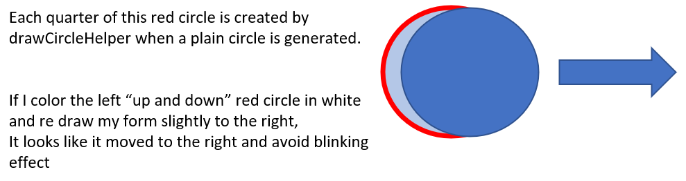
    One of the challenges on this project is to also run on 8 bits platform like Atmega328p. TOF or relay aren't a real problem but LCD is very complicated for two reasons :

    Problem 1 : Memory

    With its 32kb of Flash, the Atmega328p can't store a lot of information onboard. Let's imagine that we want to store an image encoded on a RGB565 (2 bytes) of 128x128 pixels. We have : 128x128x2 = 32768 bytes. A single image on a small screen would already completely overload the memory!

    Problem 2 : Refresh Rate

    To refresh this screen of 16384 pixels it will be necessary to pay also attention to speed. The Atmega328p has only one SPI. If you want to use, for example, an SD card to overcome the memory problem. SD and LCD will be on the same bus. So you will have to do the same on the SPI: get the image from the SD and send it to the LCD...

    I found someone who have a solution to this problem HERE, but it implies a RAW storage of the images, which can be quite difficult to stay flexible.

    Implementation

    To start with, I imagined how to represent my hedgehog with simple shapes that I could generate with the Arduino GFX library. Here, my screen displays the eyes (2 circles) and the nose (1 circle + 3 mini circles) of my hedgehog. I can thus simply use GFX without having to load an image in memory. In addition, I can draw the circles without reloading the whole screen, which allows me to gain a lot of speed.

    In order to validate the shapes and movements of the eyes and nose, I started by a simulation on Keynote :

    On the LCD, to implement a movement simply, I used two algorithm : 

    1. I redraw the previous shape in black and then I redraw it with color to its new position. This is a very simple way, but it make the screen a bit blinky... 
    2. From GFX Library, to move a "fillCircle()" in a direction, I used a hidden function called "drawCircleHelper()" to remove only a part of the border circle. 

    On the Arduino MKR 1010 or Teensy 3.6, I can take advantage of the speed and the extra memory to make my animations more fluid and complex.

    On the 3D Design and prototypes, I used a Teensy 3.2. 

    Speed MaxBitFlash
    Arduino UNO16Mhz832kbit
    Teensy 3.296MHz32256kbit
    Teensy 3.6240Mhz321024kbit
    MKR 101048Mhz32256kbit

View all 13 instructions

Enjoy this project?

Share

Discussions

jean.perardel wrote 07/20/2021 at 13:05 point

Thanks a lot :)

  Are you sure? yes | no

Dan Maloney wrote 06/01/2021 at 17:04 point

That's a pretty clever idea. And the hedgehog case is kind of adorable. Nice stuff!

  Are you sure? yes | no

Similar Projects

Does this project spark your interest?

Become a member to follow this project and never miss any updates