Introduction
Do you want to learn how to build your first combat robot with Arduino?
In this project you will learn:
- How the complete structure of a mobile sumo combat robot in MDF works;
- Implement a power input system to charge your combat robot's battery;
- How to increase your robot's operating autonomy through batteries;
- How to design wheels for your mobile robot with a lower cost and greater customization;
Robot combat is a great style to motivate people to create different robots. These robots are created with a single objective: to beat other robots and become the best in the championship.
There are several categories of robotics championships. There are object rescue, line follower, football and sumo championships, for example.
In this project we will focus on teaching you how to create a sumo robot. In this championship we have two robots in a combat space. They need to fight each other in order to get each other out of the fighting field.
After a few rounds of combat it is possible to determine who will be the winner. These robots have two control possibilities: they can work autonomously or tele-operated by the user.
Now, let's start the sumo combat robot development process.

This sumo combat robot is made up of the following electronic components:
- 1 Arduino UNO
- 1 Ultrasonic sensor;
- 1 Seesaw Key;
- 2 Direct Current Motors
- 1 Ultrasonic Sensor HC-SR04
- L298N DC Motor Driver
- 1 TP4056 Module
- 2 18650 Lithium Batteries
Now, we'll start the full presentation of the sumo combat robot with the Arduino.
The electronic circuit structure of the Arduino sumo combat robot
The robot was created with a reduced size and few parts. The objective is to allow the robot to be light and fast for sumo competition.
The figure below shows the complete structure of the sumo combat robot.
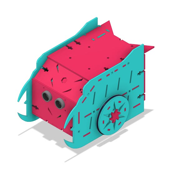
1 / 4
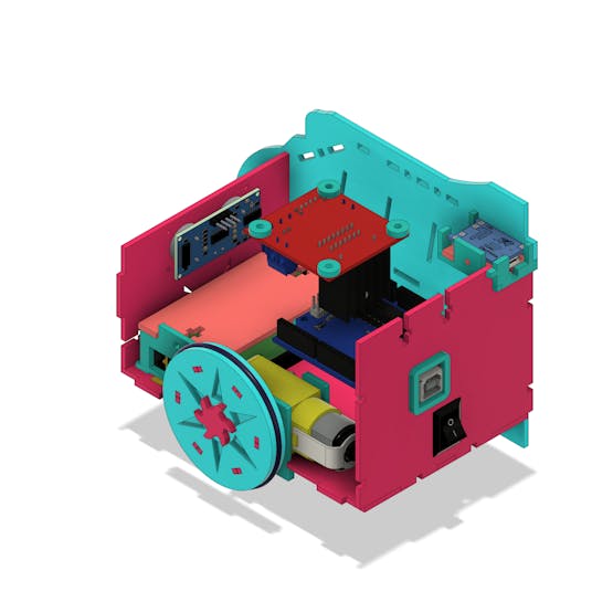
Its internal structure is divided into 2 parts: upper and lower. See the figure below.
_v2_1fwScWscB9.png?auto=compress%2Cformat&w=740&h=555&fit=max)
In the upper structure we have the Arduino, the TP4056 module, the L293D driver and the ultrasonic sensor. Below we have the lithium batteries, the 2 motors and the button to turn the robot on/off.
In the figure below the components can be seen from another angle.
Now, let's see how these components are electrically interconnected.
Electrical connection of electronic components
The circuit below represents the connection of the robot's electronic components.

The power supply consists of 2 18650 lithium batteries with an output voltage of 7.4V. The switch is responsible for turning the robot's operation on/off.
After power on, the Arduino is initialized and the control logic is executed.
We provide an Arduino for you to download and assemble your project. You just won this Arduino!
Use the JLCPCB Arduino Compatible printed circuit board presented below.

You can obtain the Arduino JLCPCB compatible PCB for your projects for $2 in your first order with the link: Earn my PCBs Arduino Compatible.
In addition to Arduino, we built a shield for Arduino UNO. This shield facilitates the assembly process of your Arduino projects and reduces bad contact between the wires. Link do download gerber files of the shield.

Download of your shield for Arduino UNO.
Use the JLC-RECE coupon, earn a $2 off discount, and earn FREE5 PCBs.
The Arduino system will wait for a command sent via bluetooth by the user. Upon receipt of this command, the robot will move in the direction desired by the user. This will be done by activating the two DC motors with the L298N drive.
In addition to steering, the driver can control the speed of the robot's wheels via the Arduino's PWM pins.
Through motion control your robot will be able to attack and dodge the opponent robot.
In addition, we have an ultrasonic sensor circuit. We can use it to put the robot into autonomous operation.
Now, let's continue the discussion of the robot's...
Read more »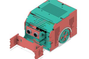
 RobsonCouto
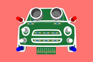

 selena1995