Introduction
Do you want to learn how to build your first combat robot with Arduino?
In this project you will learn:
- How the complete structure of a mobile sumo combat robot in MDF works;
- Implement a power input system to charge your combat robot's battery;
- How to increase your robot's operating autonomy through batteries;
- How to design wheels for your mobile robot with a lower cost and greater customization;
Robot combat is a great style to motivate people to create different robots. These robots are created with a single objective: to beat other robots and become the best in the championship.
There are several categories of robotics championships. There are object rescue, line follower, football and sumo championships, for example.
In this project we will focus on teaching you how to create a sumo robot. In this championship we have two robots in a combat space. They need to fight each other in order to get each other out of the fighting field.
After a few rounds of combat it is possible to determine who will be the winner. These robots have two control possibilities: they can work autonomously or tele-operated by the user.
Now, let's start the sumo combat robot development process.

This sumo combat robot is made up of the following electronic components:
- 1 Arduino UNO
- 1 Ultrasonic sensor;
- 1 Seesaw Key;
- 2 Direct Current Motors
- 1 Ultrasonic Sensor HC-SR04
- L298N DC Motor Driver
- 1 TP4056 Module
- 2 18650 Lithium Batteries
Now, we'll start the full presentation of the sumo combat robot with the Arduino.
The electronic circuit structure of the Arduino sumo combat robot
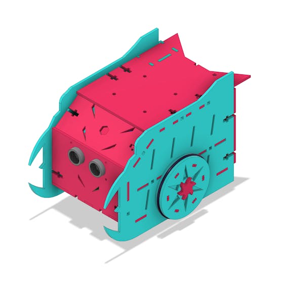
The robot was created with a reduced size and few parts. The objective is to allow the robot to be light and fast for sumo competition.
The figure below shows the complete structure of the sumo combat robot.
1 / 4
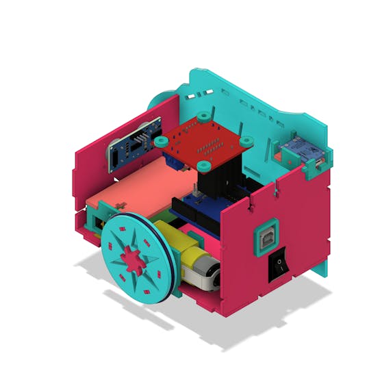
Its internal structure is divided into 2 parts: upper and lower. See the figure below.
_v2_1fwScWscB9.png?auto=compress%2Cformat&w=740&h=555&fit=max)
In the upper structure we have the Arduino, the TP4056 module, the L293D driver and the ultrasonic sensor. Below we have the lithium batteries, the 2 motors and the button to turn the robot on/off.
In the figure below the components can be seen from another angle.
Now, let's see how these components are electrically interconnected.
Electrical connection of electronic components
The circuit below represents the connection of the robot's electronic components.

The power supply consists of 2 18650 lithium batteries with an output voltage of 7.4V. The switch is responsible for turning the robot's operation on/off.
After power on, the Arduino is initialized and the control logic is executed.
We provide an Arduino for you to download and assemble your project. You just won this Arduino!
Use the JLCPCB Arduino Compatible printed circuit board presented below.

You can obtain the Arduino JLCPCB compatible PCB for your projects for $2 in your first order with the link: Earn my PCBs Arduino Compatible.
In addition to Arduino, we built a shield for Arduino UNO. This shield facilitates the assembly process of your Arduino projects and reduces bad contact between the wires. Link do download gerber files of the shield.

Download of your shield for Arduino UNO.
Use the JLC-RECE coupon, earn a $2 off discount, and earn FREE5 PCBs.
The Arduino system will wait for a command sent via bluetooth by the user. Upon receipt of this command, the robot will move in the direction desired by the user. This will be done by activating the two DC motors with the L298N drive.
In addition to steering, the driver can control the speed of the robot's wheels via the Arduino's PWM pins.
Through motion control your robot will be able to attack and dodge the opponent robot.
In addition, we have an ultrasonic sensor circuit. We can use it to put the robot into autonomous operation.
Now, let's continue the discussion of the robot's mechanical structure.
All robot parts are fitted via T-joints with M3 screws. This allows for a better fit and increased rigidity in the structure of the mobile robot.
See the snap-on structure of our mobile robot's battery holder. The position of the support was defined on the front of the robot with the aim of reducing its size.
The batteries are installed in the bracket with a wire exit opening on its side.
How to remove the battery to recharge your energy?
It is not necessary to remove the battery to charge its energy, as we are using the TP4056 module. See the module in the figure below.

The TP4056 module will be responsible for receiving power and recharging the 18650 lithium batteries.
How does it work and what are the main features of the TP4056 module?
This model is responsible for powering Li-Ion 18650 batteries through the constant voltage current charging method. The old modules did not have this protection system, however, this is already presented in the current models.
In this module there are two integrated circuits: the TP4056 and the DW01. The DW01 integrated circuit is responsible for carrying out the battery current protection.
The TP4056 module supplies a charging current of 1A and, after that, it interrupts the current when the recharge is finished.
Here are some important features of this module:
- Protects your battery from over-discharge. It prevents your battery from discharging for voltage values below 2.4V.
- If a connected battery is discharged below 2.4V, then the module will cut the battery output power until its voltage is recharged to a value above 3V.
- The module will safely charge your battery to a value of 4.2V.
- The module will cut the output from the battery if the discharge rate exceeds 3A or if a short-circuit condition occurs.
Which power supply should we connect to charge the batteries?
The power supply must provide at least 1A for the battery charging process to take place correctly. The power cable must be USB Micro or USB C type. In addition, you can use + and - pins. See the diagram in the figure below.
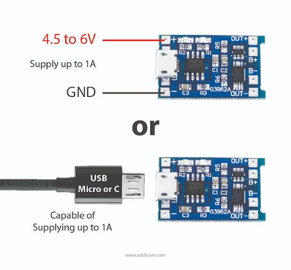
Most modern phone/USB chargers can deliver 1A or more.
Check the information in the power supply manual and carry out the process safely.
The module has 2 LED indicators during the battery charging process. Red indicates battery charging and blue indicates full charge.

See USB connector access structure to recharge the battery.

In the figure above, we can see the mini USB connector in the upper right corner. The user must connect the cable to start charging the battery.
In addition, it is possible to observe the Arduino's USB connector, to carry out the robot's programming. This avoids removing Arduino for logic programming and testing. The button, shown in the figure, is used to turn the robot system on and off.
Now look at the figure one more time and see the wheel structure. Do you know how they were built?
Let's look at the wheel structure of our mobile robot.
There are different models of wheels for mobile robots on the market. However, they are not easy to find in all stores and some are very expensive. Also, we were unable to customize the wheel for our project.
Thinking about this problem, we decided to create a model of a custom wheel for our robot.
The wheel has a design, shape and size that ensure a good match with our mobile sumo robot model.

This wheel is composed of 2 materials in its formation: MDF structure and the o-ring ring.
- MDF is the material responsible for creating the wheel structure.
- The o-ring is a circular rubber and is used to increase the wheel's grip on the ground.
Now, let's look at the programming logic developed. The logic allows the robot to avoid obstacles through the use of the ultrasonic sensor.
Development of programming logic for autonomous mode
The robot will move around the environment alone and dodge anything in front of you.
How does it all work? Shall we understand?
For this project we developed the code presented below.
#define Motor1A 2#define Motor1B 3#define Motor2A 4#define Motor2B 5#define echoPin 9#define trigPin 8long tempo = 0;byte distancia = 0;void setup() { Serial.begin(9600); pinMode(Motor1A, OUTPUT); pinMode(Motor1B, OUTPUT); pinMode(Motor2A, OUTPUT); pinMode(Motor2B, OUTPUT); pinMode(echoPin, INPUT); pinMode(trigPin, OUTPUT);}void loop() { digitalWrite(trigPin, LOW); delayMicroseconds(2); digitalWrite(trigPin, HIGH); delayMicroseconds(10); digitalWrite(trigPin, LOW); tempo = pulseIn(echoPin, HIGH); delay(300); distancia = tempo * (0.034/2); Serial.println(distancia); if(distancia >= 10) { frente(); } else { parar(); delay(500); direita(); delay(1000); parar(); } }void frente(){ digitalWrite(Motor1B, LOW); digitalWrite(Motor2B, LOW); digitalWrite(Motor1A, HIGH); digitalWrite(Motor2A, HIGH);}void re(){ digitalWrite(Motor1A, LOW); digitalWrite(Motor2A, LOW); digitalWrite(Motor1B, HIGH); digitalWrite(Motor2B, HIGH);}void parar(){ digitalWrite(Motor1A, HIGH); digitalWrite(Motor2A, HIGH); digitalWrite(Motor1B, HIGH); digitalWrite(Motor2B, HIGH); }void direita(){ digitalWrite(Motor1B, LOW); digitalWrite(Motor2A, LOW); digitalWrite(Motor1A, HIGH); digitalWrite(Motor2B, HIGH);}
In the first step, we define the pins used by the motors, ultrasonic sensor, and the program variables. See the code portion below.
#define Motor1A 2#define Motor1B 3#define Motor2A 4#define Motor2B 5#define echoPin 9#define trigPin 8long tempo = 0;byte distancia = 0;
In the setup function, we configure the pins as inputs and outputs based on how they will be used in the code.
void setup() { Serial.begin(9600); pinMode(Motor1A, OUTPUT); pinMode(Motor1B, OUTPUT); pinMode(Motor2A, OUTPUT); pinMode(Motor2B, OUTPUT); pinMode(echoPin, INPUT); pinMode(trigPin, OUTPUT);}
Now let's understand the main logic in the loop function.
void loop() { digitalWrite(trigPin, LOW); delayMicroseconds(2); digitalWrite(trigPin, HIGH); delayMicroseconds(10); digitalWrite(trigPin, LOW); tempo = pulseIn(echoPin, HIGH); delay(300); distancia = tempo * (0.034/2); Serial.println(distancia); if(distancia >= 10) { frente(); } else { parar(); delay(500); direita(); delay(1000); parar(); } }
First, a code block was created to read the ultrasonic sensor. See the code below.
digitalWrite(trigPin, LOW); delayMicroseconds(2); digitalWrite(trigPin, HIGH); delayMicroseconds(10); digitalWrite(trigPin, LOW); tempo = pulseIn(echoPin, HIGH); delay(300); distancia = tempo * (0.034/2);
This code portion is used to trigger the sensor, receive the echo signal, and calculate the time.
From the time, the Arduino can calculate the distance between the robot and any obstacle in front of it.
After that, it's time to check for an obstacle. This is done through the conditions below.
if(distancia >= 10) { frente(); } else { parar(); delay(500); direita(); delay(1000); parar(); }
The Arduino checks whether the distance is greater than or equal to 10. If this is true it means that there is no obstacle in front of the robot, and it will be moved forward.
The function responsible for activating the wheels in the forward direction (clockwise direction) is shown below.
void frente(){ digitalWrite(Motor1B, LOW); digitalWrite(Motor2B, LOW); digitalWrite(Motor1A, HIGH); digitalWrite(Motor2A, HIGH);}
In addition to this situation, we can have the indication of an obstacle when the distance is less than 10 cm. In that case, the following command block will be executed. See the code portion below.
{ parar(); delay(500); direita(); delay(1000); parar(); }
The Arduino stops the 2 motors, waits 500 ms, turns the robot to the right, and stops the robot again.
After that, the code flow goes back to the beginning, performs a new reading, and makes a new decision. If there is no more obstacle, the robot will move forward. Otherwise, the robot will rotate to the right again.
This is how programming logic works for the autonomous operating mode.
In the next article, we will explain how robot works in artifact rescue mode. In the next article, we will teach you how to create the robot app and control to rescue artifacts.
At this moment I ask that you leave your comment with doubts and like this text to let us know that you liked the story of robot.
Acknowledgment
We thank Ludic Robot School and the company JLCPCB for offer support to create this project.
Use the JLCPCB Arduino Compatible printed circuit board presented below.

You can obtain the Arduino JLCPCB compatible PCB for your projects for $2 in your first order with the link: Earn my PCBs Arduino Compatible.
In addition to Arduino, we built a shield for Arduino UNO. This shield facilitates the assembly process of your Arduino projects and reduces bad contact between the wires. Link do download gerber files of the shield.
Download of your shield for Arduino UNO.
Use the JLC-RECE coupon, earn a $2 off discount, and earn FREE5 PCBs.