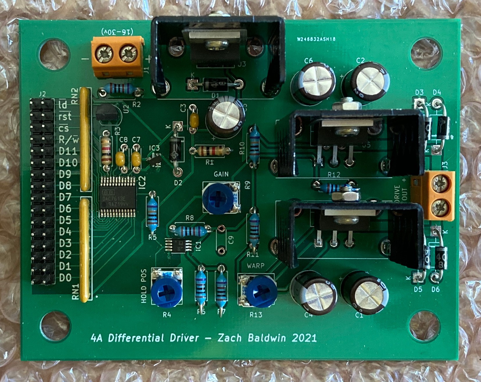
There we go!
Here's the rundown on the layout: The left side has the digital interface header and the DAC. Above the digital section is the power input terminal block. This accepts 16-30v, single rail. Next to the power input is the 7805 for the digital section (the heat sink is not needed, but I figured it would not hurt to put it on). Almost everything from R5 to the right is the analog section. IC1 is a dual op amp that takes care of creating the VCC/2 voltage reference and amplifying the DAC's output range. The two TO220-5 packages on the right side are the high current drivers for the coils. Finally on the right edge are some protection diodes and the terminal block for connecting the axis coil.
Since the mirror gimbal has two axes of motion, two drivers are needed. I had originally intended on combining both axes onto a single board, but ended up going with a single axis per board. This was partly so the same circuit did not have to be routed twice and also since I thought that mounting options for two boards were more flexible than one for a large board.
Below, is a really quick demo showing a simple test where both axes are fed a triangle waveform that ranges from 0x3F to 0xC0. I am using the upper 8 bits of the DAC's inputs with the lowest 4 bits held high by the boards' pull up resistor networks. Each driver has its own /CS line, meaning that just like chips on a computer bus, each DAC can be individually selected for loading data. The /LD lines for the DACs are tied together, allowing the output of each DAC to be updated simultaneously (/LD moves the data from the latches to the DAC's output), reducing the chance of "stair stepping" in the laser's position for 45 degree movements.
Next up will be designing the mounts for the boards.
 Zach Baldwin
Discussions
Become a Hackaday.io Member
Create an account to leave a comment. Already have an account? Log In.