 Uri Shaked
Pi Pico Pong on PAL TV
You are going to implement a Pong game with PAL TV output. The idea is to use the Pi Pico's PIO peripheral to generate the composite PAL signals.
Deliverables
You'll need to submit a working pong game that takes advantage of the PIO peripheral to generate the composite PAL signal. You don't need to test it against a physical TV - if it works in the simulation, that's good enough.
In addition, please include your ARM assembly implementation of gcd() and square() - see class 3 homework for details.
You can choose whether to write your solution in C++ (i.e. using the Arduino Core for the Pi Pico) or in MicroPython. From my experience, MicroPython can be a challenging as you need to quickly feed the data into the PIO peripheral.
The pong game can be very basic. Two paddles, one ball, bouncing and moving the paddle with the buttons is enough. But feel free to add fancy features such as sound, 2-player support, scoring, etc. You can find some inspiration here.
Please create a Hackaday project page for your submission and add the "PI-PONG" tag so we can easily find it.
If you have any questions, you're invited to ask on the #rp2040js discord channel.
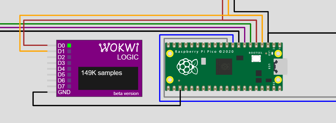
Simulation Template
You can use this simulation template for your project. The project pinout is as follows:
Pi Pico Pin | Description |
0 | UART TX - for debugging with the Serial Monitor |
2 | PAL SYNC |
3 | PAL DATA |
4 | Player 1 - Up button |
5 | Player 1 - Down button |
6 | Player 2 - Up button |
7 | Player 2 - Down button |
Notes:
- Player 2 is optional. You can also let the computer control the second player.
- The buttons have keyboard shortcuts: w/s for player 1 up/down buttons, and up arrow/down arrow for player 2 up/down buttons.
Composite PAL Signal
PAL works at 25 frames per second. However, each frame is split into two parts, called "fields". The first field contains the odd lines, and the second field contains the even lines. This is called interlacing. Each frame takes 40ms (so you get 25 frames/second), and each field takes 20ms (half that time).
Your code would need to generate and send these frames to the TV. I strongly recommend to prototype the code in the simulator. Testing on a physical TV is totally optional, but if you are interested, I included the instructions below.
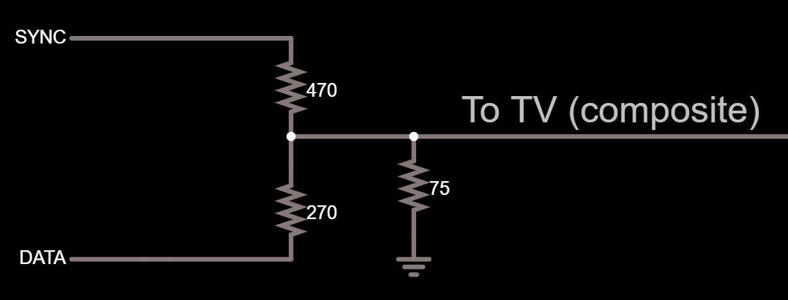
To generate the frames, you'll need to drive two signals: SYNC and DATA. In the simulation, the DATA signal is connected to the IN pin of the wokwi-tv element.
The SYNC signal indicates the start of a new frame or the start of a new line, depending on the length of the signal. This is how the TV knows when to move to the next line, or draw the next frame.
The DATA signal indicates the color of the current pixel. Drive it high for white, low for black. The faster you drive the DATA signal, the better horizontal resolution that you get. For instance, if you change the DATA signal 2 million times per second (2MHz), you get about 128 pixels/line resolution (each line is 64us, so 500ns per pixel gives at 128 pixels/line).
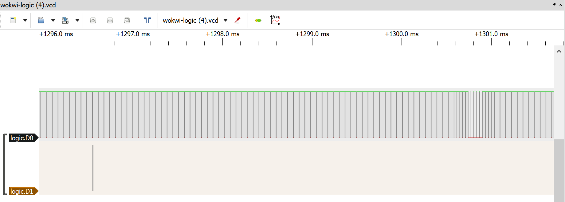
Sync Signals
Note: You can skip to the next section if you just want to get it to work in the simulator.
In general, there are three types of synchronization signals:
Short Vertical | SYNC goes low for 2us, then high for 30us |
Long Vertical | SYNC goes low for 30us, then high for 2us |
Horizontal | SYNC goes low for 4us, then high for 60us (rest of the scanline) |
Whenever the SYNC goes low, the DATA signal also has to be kept low (see below, "Composite signal", to know why).
Each field starts with a sequence of several Short Vertical and Long Vertical sync pulses. The amount of the Vertical Short pulses varies between even and odd fields:
Odd field | 6 Short Vertical pulses, then 5 Long Vertical pulses, then 5 Short Vertical pulses |
Even field | 5 Short Vertical pulses, then 5 Long Vertical pulses, then 4 Short Vertical pulses |
After sending the sequence of vertical synchronization sequence, you need to send 305 horizontal synchronization pulses, one...
Read more »

 Justin R.
 George Gardner
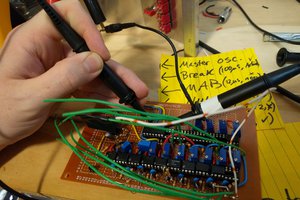
 schlottmachine
 will.stevens