Close
0%
0%

Neotron Pico

A microATX motherboard that uses a Raspberry Pi Pico as the CPU. SuperVGA output, stereo audio, a BIOS written in Rust and not much RAM!

Similar projects worth following
The Neotron Pico is designed to run Neotron OS, but as it's just a Raspberry Pi Pico at its heart, you can run anything you like on it.

Video output is 12 bit colour, just like an OCS Amiga. We have an R2R DAC, but also a proper RGB video buffer designed to drive 75 ohms, so it should be better quality than your average GPIO-into-VGA hack (like my last two projects, Monotron and Neotron 32).

There's a 16 bit stereo CODEC and an AC'97 header for your case, plus a classic pink/green/blue PC98 triple Jack at the rear.

There's an SD Card slot for storage, an STM32F0 to run the power supply, reset circuit and a couple of PS/2 ports.

There's also an SPI + I²C expansion bus for adding new features. MIDI? SCSI? Why not?!

The design files are at https://GitHub.com/Neotron-compute/neotron-pico. It's all open source hardware, and we use GitHub Actions to reliably convert the KiCad files into PDF Schematics, and Gerber files for manufacturing.

Why GitHub Actions?

Have you ever seen an open source project, but they've put all the built files (PDFs, Gerbers, Firmware HEX files, etc) in the repo with the source code. Pretty common right? But all yourself, how did they make those files? And how can you be sure which version they were made from, and that they are consistent?

This project uses GitHub Actions. There are no Gerbers in the tree - they are built on demand when the repository is tagged. And they means you can see the scripts used to build them - you literally, and by definition, have all the tools and files you need to do what GitHub does. The same goes for schematic PDFs and interactive BoM files. There can be no confusion about which version is which - it's all in the git logs, clearly tagged with each unique version number.

It's not just Open Hardware. It's Reproducible Hardware.

What's with all the comments in the schematic?

As far as possible, I've tried to get the schematics to record not just *what* something is or does, but *why*. This is not just a write-once-read-never dump of some idea I once had. I'm trying to build a learning resource for anyone who wants to know more about electronics, and what you need to make your own ATX compatible main board.

If you think you can improve on what I've done in any way, to make something clearer or to make it more functional, do send a PR!
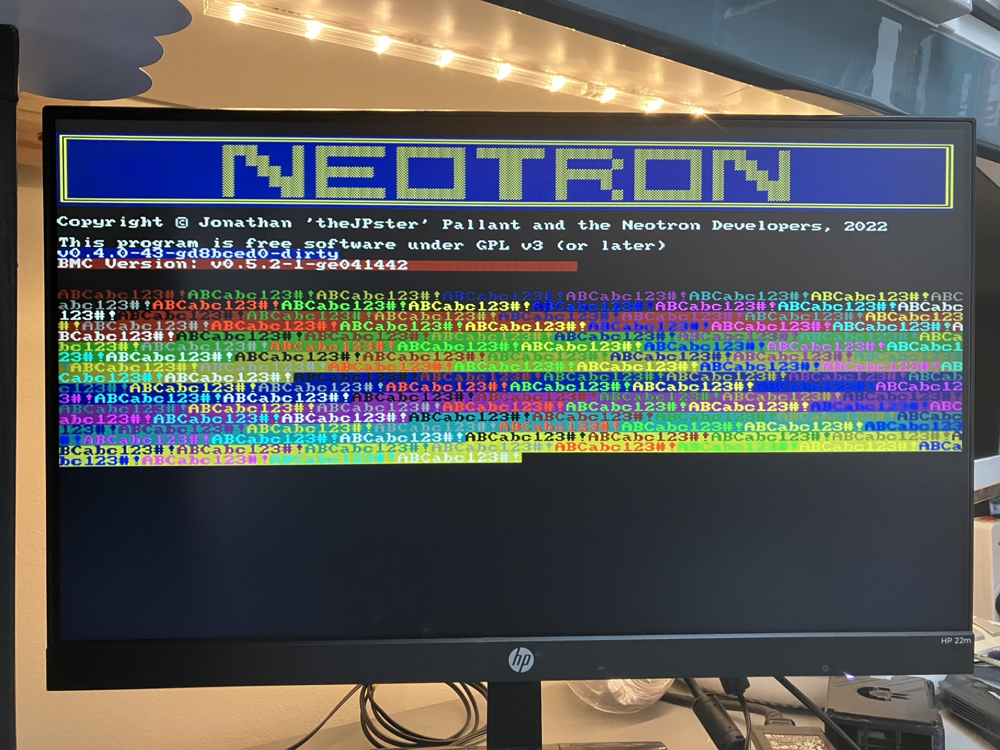
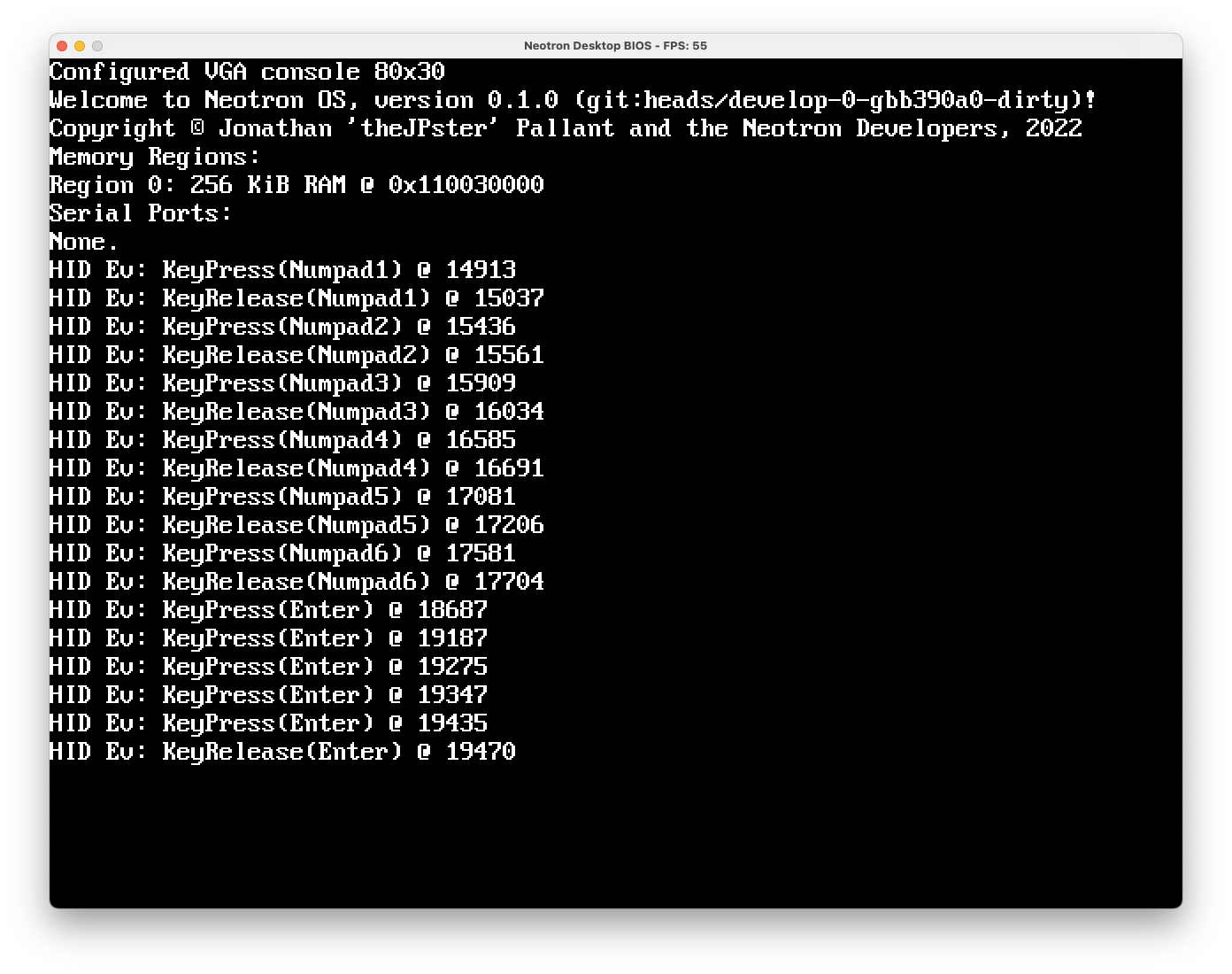
What is Neotron OS?

Neotron OS is a simple Rust-language operating system, inspired by CP/M and early MS-DOS. It's single-tasking, with a flat memory space. Basically, it's just enough OS to get your application loaded from SD Card into RAM. Once there, you can do what you like!

  • 1 × Raspberry Pi Pico
  • 1 × Texas Instruments TLV320AIC23BPW Amplifier
  • 1 × Mornsun K7805-3AR3 PSU Module
  • 1 × STM32F031K6T6 MCU
  • 1 × 74HC245 SSOP-20

View all 22 components

  • Now you can load from disk...

    Jonathan 'theJPster' Pallant05/18/2023 at 17:37 0 comments

    Over the past couple of weeks I've been working on SD Card support for the Neotron Pico. The broad schedule ran like this:

    1. Detect when a card is inserted into the slot.

    2. Detect when a card is removed from the slot.

    3. When a BIOS "List Block Devices" API is called, initialise the SD Card and report its actual capacity.

    4. Remember the fact that the card is initialised so we don't initialise it again needlessly.

    5. Update the Neotron OS so it can read and write arbitrary blocks from disk. Test this using the Neotron Desktop BIOS and a disk image.

    6. On the Pico BIOS, support the "Block Read" and "Block Write" BIOS API calls.

    7. On the Neotron OS, implement the BlockDevice trait from the SD Card library over the BIOS API calls, and implement a basic DIR command.

    8. Change the OS "load" command to load a file from disk into RAM, instead of reading keyboard input.

    9. Profit!

    Somewhere in there was a step around "re-write the embedded-sdmmc crate so it makes more sense internally, and so it allows you to create a new driver object (unsafely) without rebooting the SD Card".


    Right now, I have branches open on three different projects (Neotron Pico BIOS, Neotron OS and embedded-sdmmc) and I need to close them and push out updated versions in the right order, so the next one in the tree can depend on a published version of the previous one ... but if you have all the right branches checked out, you can do something like this:

    Now, it's a real computer!

  • Colour 80-column text, finally!

    Jonathan 'theJPster' Pallant03/05/2023 at 20:15 0 comments

    I've spent some time thinking about how to improve the PIO program that runs our Super VGA out. Currently it requires one 16-bit value per pixel, delivered from one of two ping-pong buffers each 1280 bytes long. Loading these buffers with RGB pixels based on characters read from the text buffer takes quite a lot of CPU time. If we limit ourselves to just two colours for the entire screen, we can build a small look-up table and get all 640 pixels drawn into the buffer per scan-line using about 90% CPU at 126 MHz.

    My plan was to change the PIO so that instead of taking RGB colours as input, it instead took a series of commands: some commands to load a new colour into the X or Y register, and other commands to just clock out pixels from either the X or Y registers loaded earlier. This used almost the entire PIO memory, but I thought it should work. I coded it up with a pen and paper, and then transferred it to the computer. However, I managed to break something as despite getting a sort-of picture on the screen, most of the scan-lines per missing and the picture was rolling terribly.

    I came back to it a day later, and decided to try another approach. On the Monotron, we used a huge look-up table which converted eight-bits of glyph, along with its chosen foreground and background colours, into three eight-bit values for R, G and B. The initial problem with porting this approach is that on the Neotron Pico, instead of three eight-bit values, we need eight 16-bit values (well, 12-bit values stored in 16-bit words). This blows the lookup table from 64 KiB (256 x 8 x 8 x 4 bytes) to 512 KiB (256 x 8 x 16 x 8 x 2 bytes). Plus it would be stored in off-chip Flash which has a big access latency because it's accessed over a Quad SPI interface.

    One way to shorten this table would be to use an array of functions, where the functions store the correct pattern of foreground and background colours into the given position in the scan-line buffer. We'd need 256 functions, to cover each variant of our eight-bit input. I tried this, and the performance sucked. It also chewed up so much RAM (these functions are in RAM to avoid that Flash latency) we had to decrease the amount available to the OS. That wasn't going to work.

    I also tried a 256 entry match statement, which was smaller, and faster. But still not fast enough.

    I then came across an old branch where I'd worked on this problem previously. This used a lookup table containing RGB pixels, but instead of taking eight pixels as input, it takes only two pixels and so four lookups are required. The lookup table needs to be 2048 bytes long (4 x 8 x 16 x 2 x 2 bytes), which we have space for. But does it run fast enough?

    No.

    Previously I had to overclock the chip to 201.6 MHz (eight clocks per pixel) to get this version to work. But, I have better benchmarking tools now - I output the precise time it takes to complete the render into the scan-line buffer using the dedicated LED on the Pico. Placing an oscilloscope on the LED's control line allows me to measure the time taken using an oscilloscope. As it turns out, winding the clock speed up from 126 MHz (five clocks per pixel) to 151.2 MHz (six clocks per pixel) is just enough to get it done. We're using 90% of Core 1 to do the drawing, but it's stable.

    Time for some test code to check all the colour combinations, and a little bit of ASCII art to show off...

    Maybe I'll come back to the PIO improvements another day, but for now this is a big achievement. We have full 80 column VGA text mode, in either 25, 30, 50 or 60 lines, with 16 foreground colours and 8 background colours, just like on the IBM PS/2 and other VGA compatible systems. With a simple ANSI sequence interpreter in the OS, the world of Bulletin Board ASCII art awaits!

    Also, this is better than the RC2014 Pico VGA Terminal can do (that is currently 40 column colour, or 80 column mono). I've sent them a note explaining how I got it to work. Everyone deserves 80 column colour text on their Pico!
     ...

    Read more »

  • Rev 1.1.0 PCBs pass initial tests

    Jonathan 'theJPster' Pallant11/24/2022 at 09:02 0 comments

    The delivery from JLCPCB arrived yesterday (2022-11-23). I did an unboxing video where I soldered up one example, did a smoke test, programmed the two processors and showed we get VGA video output.

    Check it out!


  • BIOS updates

    Jonathan 'theJPster' Pallant11/16/2022 at 20:42 0 comments

    I worked on the Neotron BIOS interface this week. I merged a bunch of long-standing changes around sharing a VGA-compatible text framebuffer, and added back in Block Device support. I also updated the Neotron Desktop BIOS and the Neotron OS, so you can now get Key Events from the pix-engine GUI window forwarded into the OS via the BIOS HID API.

  • v1.1.0 boards for Beta Members are in production!

    Jonathan 'theJPster' Pallant11/16/2022 at 15:26 0 comments

    I hit BUY at JLCPCB, and ordered:

    30 off Rev 1.0.0 (using up all the SMD parts I had pre-purchased and had JLC stash away for me)

    25 off Expansion Card Template v0.7.0

    Let's hope they work! If you want to buy one, get in touch and I'll see what I can do. Or order your own using the files at https://github.com/Neotron-Compute/Neotron-Pico/releases

  • Beta Applications Open

    Jonathan 'theJPster' Pallant10/14/2022 at 09:01 0 comments

    You can now apply to be a Beta Tester and get a free Neotron Pico Kit:


    Sign up form and terms and conditions here: https://forms.gle/kxvUtNGSfCFAbtvo6

  • Audio and PS/2 port testing

    Jonathan 'theJPster' Pallant09/29/2022 at 11:26 0 comments

    In the last post I referred to some testing of the Audio CODEC using CircuitPython. Here's a video showing the code, with the Neotron audio in the background.


    I also should mention that the PS/2 keyboard is being received on the BMC chip correctly, but work continues on getting data from the BMC to the main RP2040. Comms is working, but only at around 1 MHz currently. Here's a video showing programming the BMC, keycodes being sent to the laptop over the debug log, and the PC Speaker doing a short beep for every keypress.

  • Rev 1.0.0 testing complete!

    Jonathan 'theJPster' Pallant09/29/2022 at 11:04 0 comments

    As a bit of an experiment, I thought I'd try loading CircuitPython for the Raspberry Pi Pico onto my Neotron Pico board. Whilst the point of the board is to develop and run the Neotron OS, I found that Circuit Python was pretty useful for developing PCB tests and checking out various bits of functionality. The main advantage was that I could interact with well-tested libraries and not have to wonder if my code was wrong or the PCB was wrong!

    Using the Adafruit I2C library I was able to talk to the Texas Instruments Audio CODEC and configure the various volume and audio source selection registers. This then enabled analog 'sidetone' between the Line In and the Headphone Out, so I was able to verify that those paths worked. I then switched to the Microphone input and got ... nothing. Much fiddling ensued to no avail, but when I went to unplug the microphone, I heard it pop into life. It turns out I'd set it up for a stereo microphone (mixed down to mono), whereas the mic I was using was a mono mic with only Tip and Sleeve. This meant the Ring contact in the jack was shorted to Sleeve, which was GND, but my circuit was shorting Tip to Ring - thus Tip was shorted to GND and there was no audio. The workaround to only half insert the jack so that Tip connects to the Ring contact only, and the Sleeve doesn't reach as far as the Ring contact. I'll put a fix on the PCB to take audio from Tip only, and send the 5V Mic Bias signal to Ring - if the microphone doesn't need the bias, it's fine for it to go to Ground. But with the jack half-inserted, we've got a functioning PA system!

    The same I2C library was used in conjunction with the Adafruit DS1307 driver, and we can confirm the RTC is ticking away nicely.

    Next I turned my attention to the MCP23S17 chip and quickly knocked up a Python equivalent of the driver I'd already written. Once I was happy I was driving the Debug LEDs, I set the chip to permanently select CS1 and then started up the Adafruit SD card library. Happily this was able to not only read directory listings off the card, but was able to do it at 25 MHz! Excellent news.

    The final part to test was the expansion slots. I only have one card edge connector installed currently, in slot 3. But I built up a Neotron Expansion card (the template design with no changes) and I was very quickly running a larsen scanner on the expansion card LEDs, whilst simultaneously running a counter on the on-board LEDs. This shows the 3:8 decoder is working, and it correctly isolates bus devices whilst the IO chip itself is updated. Success!

    So - to sum up - a small change is needed to the microphone circuit to better support mono microphones, and then I think we're ready to order 25 units of Rev 1.1.0.

  • Rev 1.0.0 is alive!

    Jonathan 'theJPster' Pallant08/08/2022 at 17:37 1 comment

    The latest rev 1.0.0 boards arrived today. I worked through a test procedure carefully:

    1) Visual Inspection

    2) Load through-hole components (and VGA buffer JLCPCB didn't have in stock), but leaving out the PSU

    3) 12V input at 40mA current limit showed no issues

    4) Manually apply 3.3VP to R1303 and check DC_ON pin of PSU header goes to 5.6V

    5) Flash STM32 and check we can power on and power off the board (no PSU fitted still) with the button, and that the power LED works

    6) Fit the PSU module, check 5.0V and 3.3V rails OK (5.03V and 3.29V)

    7) Fit the Raspberry Pi Pico and check the VGA output

    Still to do:

    1) Talk to the CODEC over I2C and do audio loop-back tests

    2) Talk to the MCP23S18 over SPI and drive the debug LEDs

    3)  Talk to an expansion card

    4) Talk to the SD card

    5) Check the PS/2 ports work

  • Grant Funding and Rev 1.0.0 almost ready...

    Jonathan 'theJPster' Pallant07/20/2022 at 16:31 1 comment

    Back in May 2022, the Rust Foundation awarded funds to the Rust community through their Community Grants Programme. My bid for was funds to cover the next around of Neotron Pico PCBs, and I was lucky enough to receive $3000.

    So, I've been busy!

    I have a big box of parts with most of the through-hole components. I've also been revising the PCB design. closing out the tickets I raised on the Rev 0.5.0. There's a new board layout, various parts changes to cope with the ongoing silicon shortage, and more.

    Currently I have only a few tickets left, and then it's off to JLCPCB to order another batch of five. These will be used for testing, and if functional, distributed to people who want to help with the PCB testing. Assuming the issue list is sufficiently short, there will then be a "production" run of 25 boards. As these have been paid for by the Rust Foundation, they will be given away for a nominal sum as "kits" containing a half-populated PCBA and a selection of through-hole components, such as sockets. These can then be used to get some progress on the BIOS, the BMC firmware and finally the Neotron OS itself.

View all 17 project logs

Enjoy this project?

Share

Discussions

adam.klotblixt wrote 06/17/2021 at 20:30 point

A very nice concept! A quad-spi psram would be a great expansion for this, like on the Esp32 modules. Have not had time to make/find any pio interface software yet.

  Are you sure? yes | no

Jonathan 'theJPster' Pallant wrote 06/18/2021 at 10:33 point

Unfortunately, the QSPI XIP silicon on the RP2040 cannot handle writes - it is read-only. You could make a QSPI interface out of a PIO block, but it will not be memory mapped - you will have to call functions to page blocks in and out of SRAM, just like using an SD Card.

  Are you sure? yes | no

adam.klotblixt wrote 06/18/2021 at 12:00 point

Yes, a PIO-block was what I envisioned. As an add-on expansion card to the nice slot system :D
It will be slower than natively memory mapped for sure, but still very usable. Especially if coupled with a small software cache.

  Are you sure? yes | no

Similar Projects

Does this project spark your interest?

Become a member to follow this project and never miss any updates