 David Tucker
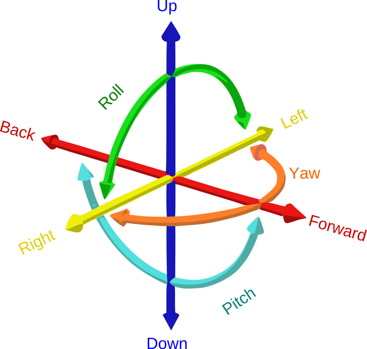
Linear motion is a mode of movement where all three degrees of rotation are fixed and two degrees of motion are fixed so that an object can only move along one axis. This is how the bold on a dead bolt moves, how a drawer slide moves, and how a sliding glass door moves.
Typically we would use some sort of a linear rail or a pair of rods with some sort of a bearing that rids on the rail or rod to constrain motion.
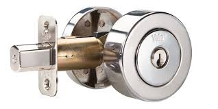
In the case of the dead bolt we use a plastic sleeve to act as a bearing with a rectangular shaped rod for the bolt itself to stop it from rotating around its primary axis of motion.
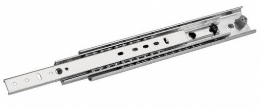
The drawer slide uses two rectangular rails with a series of ball bearings between them to allow for motion. Two sets of bearings are used to constrain the rails so they won't rotate.
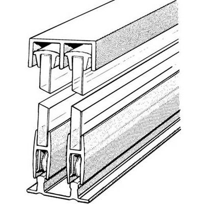
And the sliding glass door uses a linear rod at the base with wheels that ride on the rail, the top is loosely fitted into a slot to stop rotation.
We can use our own linear rails in our 3D prints to constrain motion, however this makes the design more difficult and costly to design and produce, and it makes it difficult for others to reproduce our projects because they will need to find the same rails or the print is unlikely to fit together.
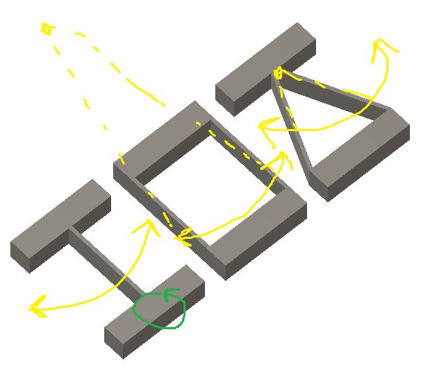
Flexures are just what they sound like, some sort of material that can flex in one direction but not in any other. By themselves a flexure is not linear but rather acts as a hinge that allows for rotational motion only. By combining two or more flexures together you can constrain the motion into a pure rotation, or a pure linear motion. In my case I want pure linear motion so I am combining 8 flexures together. Marcel Thomas has a very complete list of all the ways you can combine flexures together to create different modes of motion.
What does this have to do with 3D printing you ask. Well 3D printers are very good at printing thin tall walls precisely and can easily couple these walls together into complex shapes. By controlling the number of walls, as well as there length and height we can vary the resistance to motion as well as how far the flexure can move. Basically we can not only constrain motion but we can make the flexure act as a spring as well.
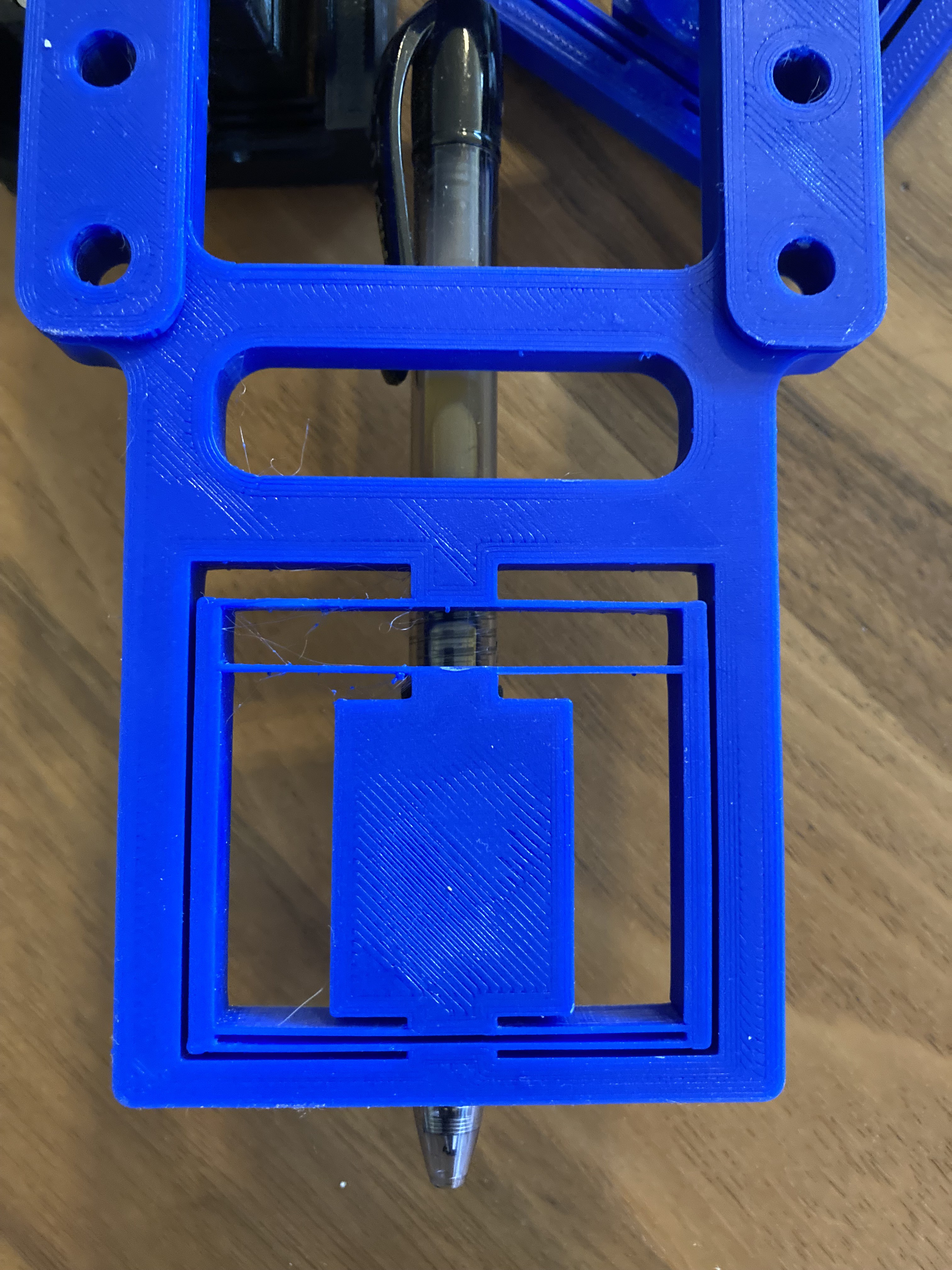
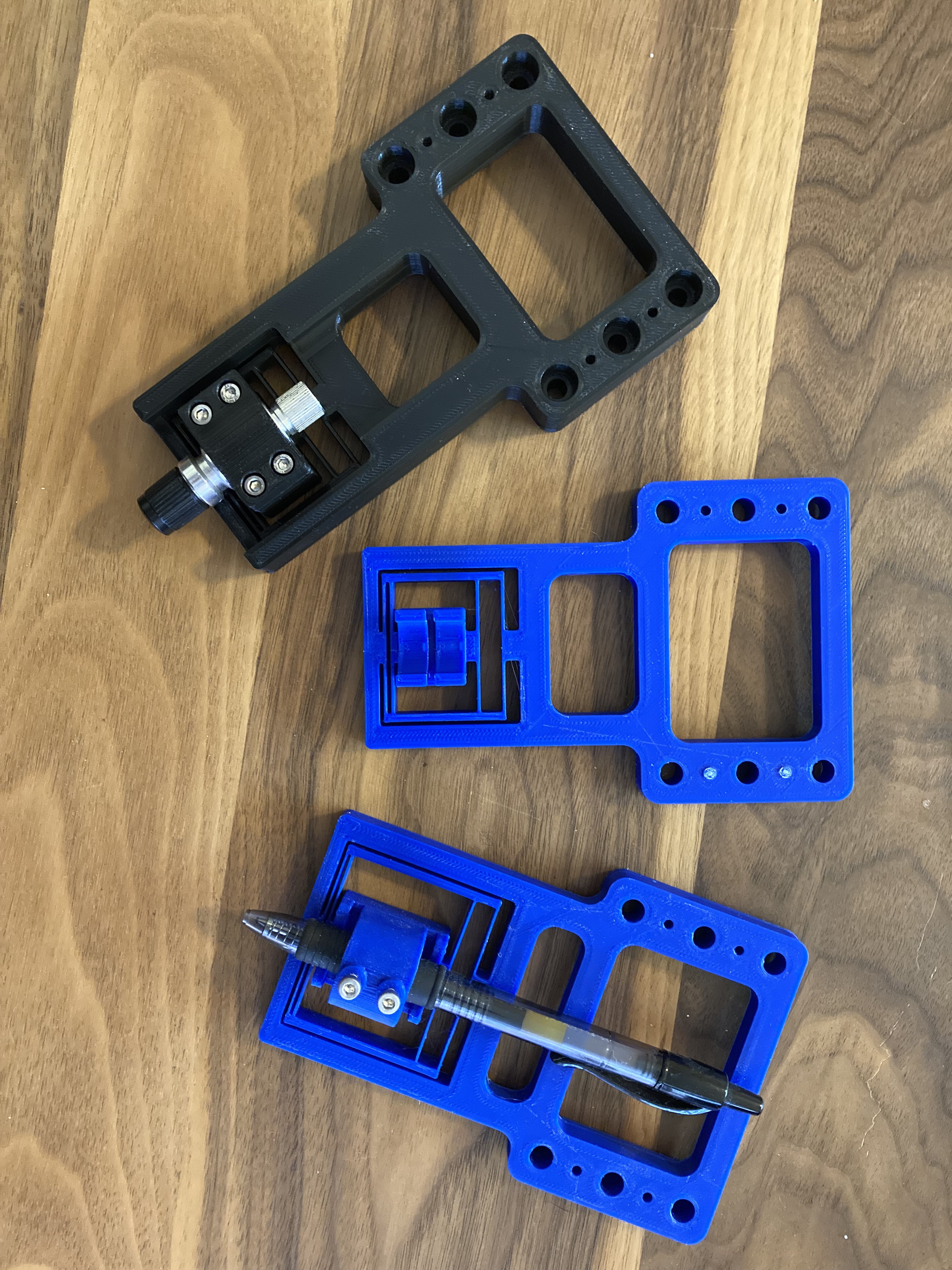
In my case I am using these flexures to act as a spring to allow a constant force of pressure to be applied when using a pen or drag knife on a cnc. I want the pen or knife to be held very rigidly in the x/y axis while allowing for a controlled amount of give in the z axis. And of course I don't want any rotation in any direction.
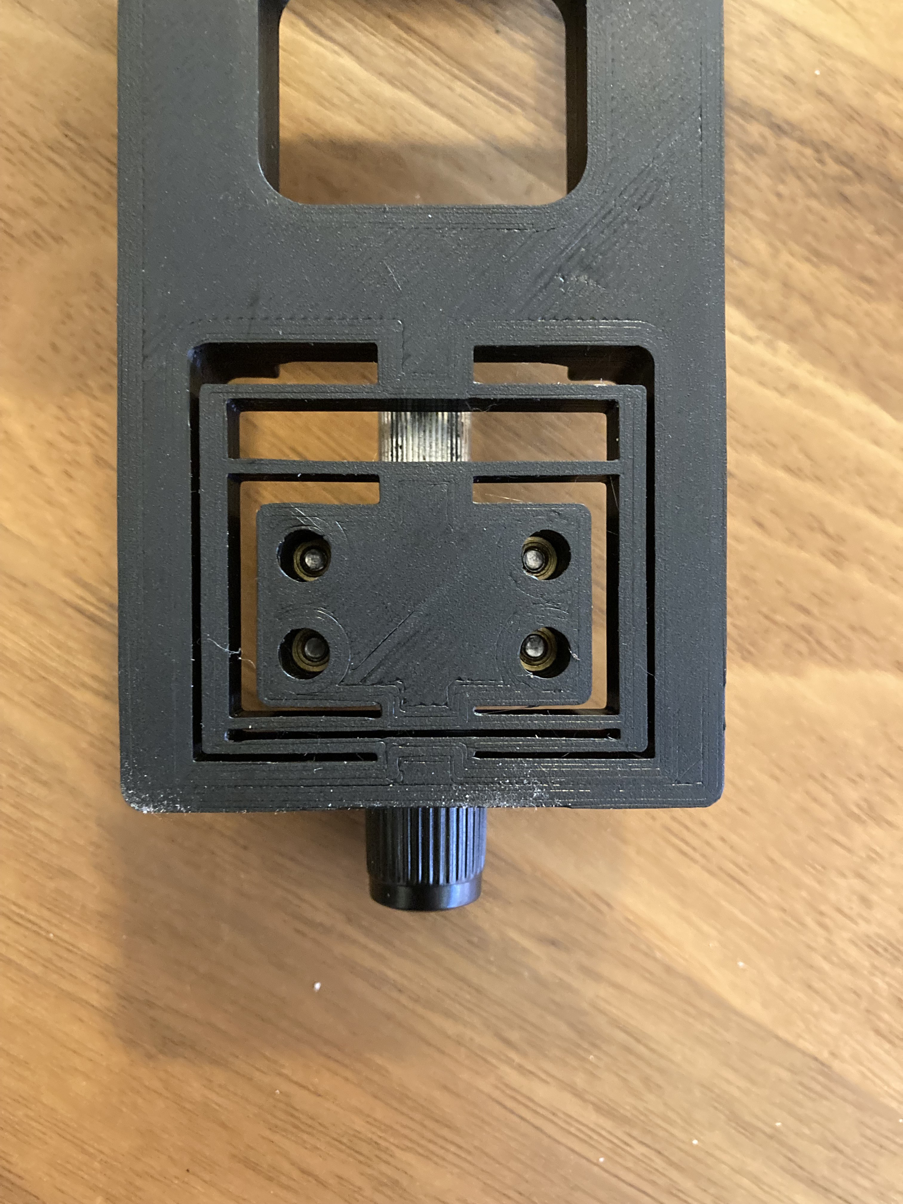
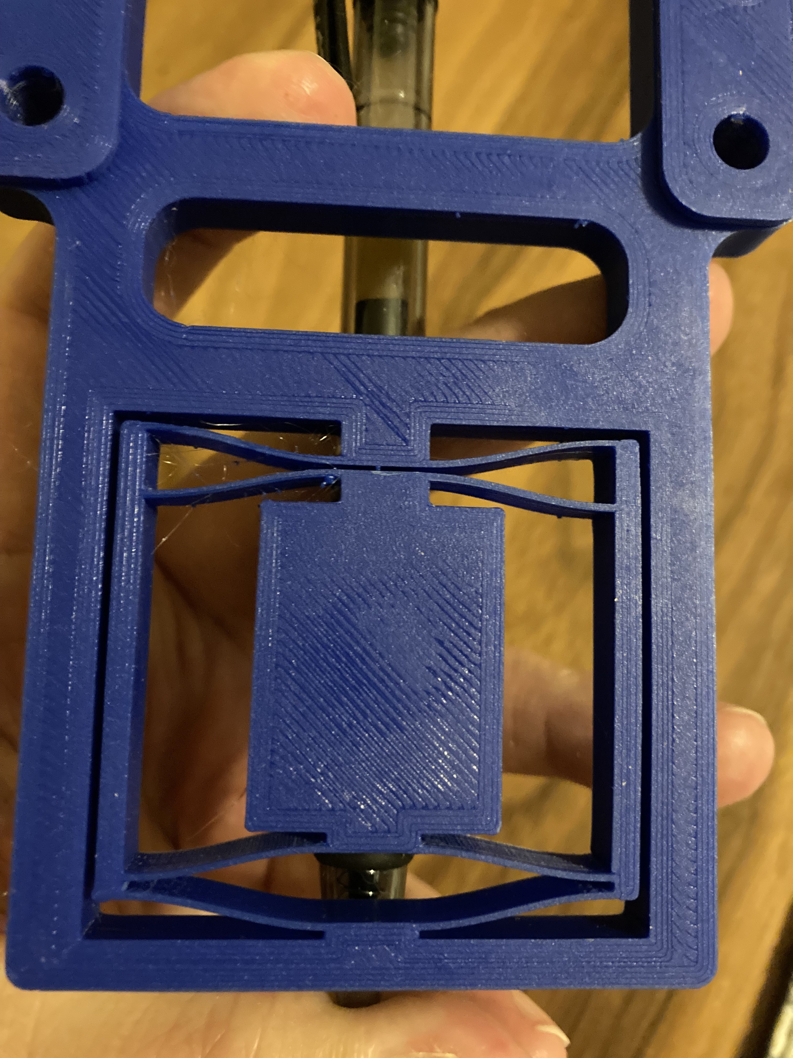
I'm using two 0.4mm walls for the flexure and have doubled up the flexures to allow for a more soft spring without needing to make the whole thing super wide. The flexures only flex in one direction so for the bottom set I was able to print them close together to further save on space. For the drag knife I need everything to be stiff with only a bit of yield in case the knife bottoms out.
You can read more on my drag knife flexure on my MultiBot project.
Anyway there is a whole world of possibilities here, I have only scratched the surface. You can use these for a wide array of precision motion systems. Hopefully this sparks some interest in you.
---
Here are all my notes on my experiments with this drag knife.
https://hackaday.io/project/176110/log/192725-blade-runner
https://hackaday.io/project/176110-multibot-cnc-v2/log/194320-what-a-drag
https://hackaday.io/project/176110/log/194370-slice-it-up
https://hackaday.io/project/176110/log/194505-flexures

 dekutree64
 Elliot
 Kārlis
Thanks for posting! Extremely interesting concept I read and saw so much about already. But haven't tried it yet. Will do now!
Can you provide a file to get started though? A non-STL one preferably? That would be sweet!