Close
0%
0%

Home Button for Keyboards

Use phone's trackpad as a pointing device.

Similar projects worth following

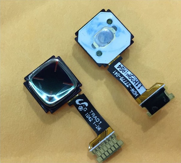
It's a common practice in custom keyboards to include some kind of a pointing device on them, so that we can move the mouse cursor without having to take the hands off the home row. A variety of devices are used: analog joysticks, thinkpad trackpoints, small trackballs. But some phones have a device that would be ideal for this: the "home" button with a built-in optical trackpad.

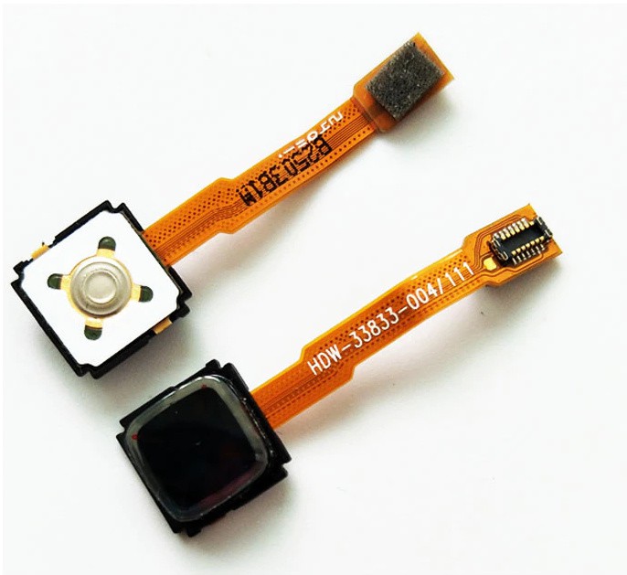
Unfortunately, even though you can easily get those buttons as replacement parts, nobody seems to be using them — and that is probably because there seems to be very little documentation.

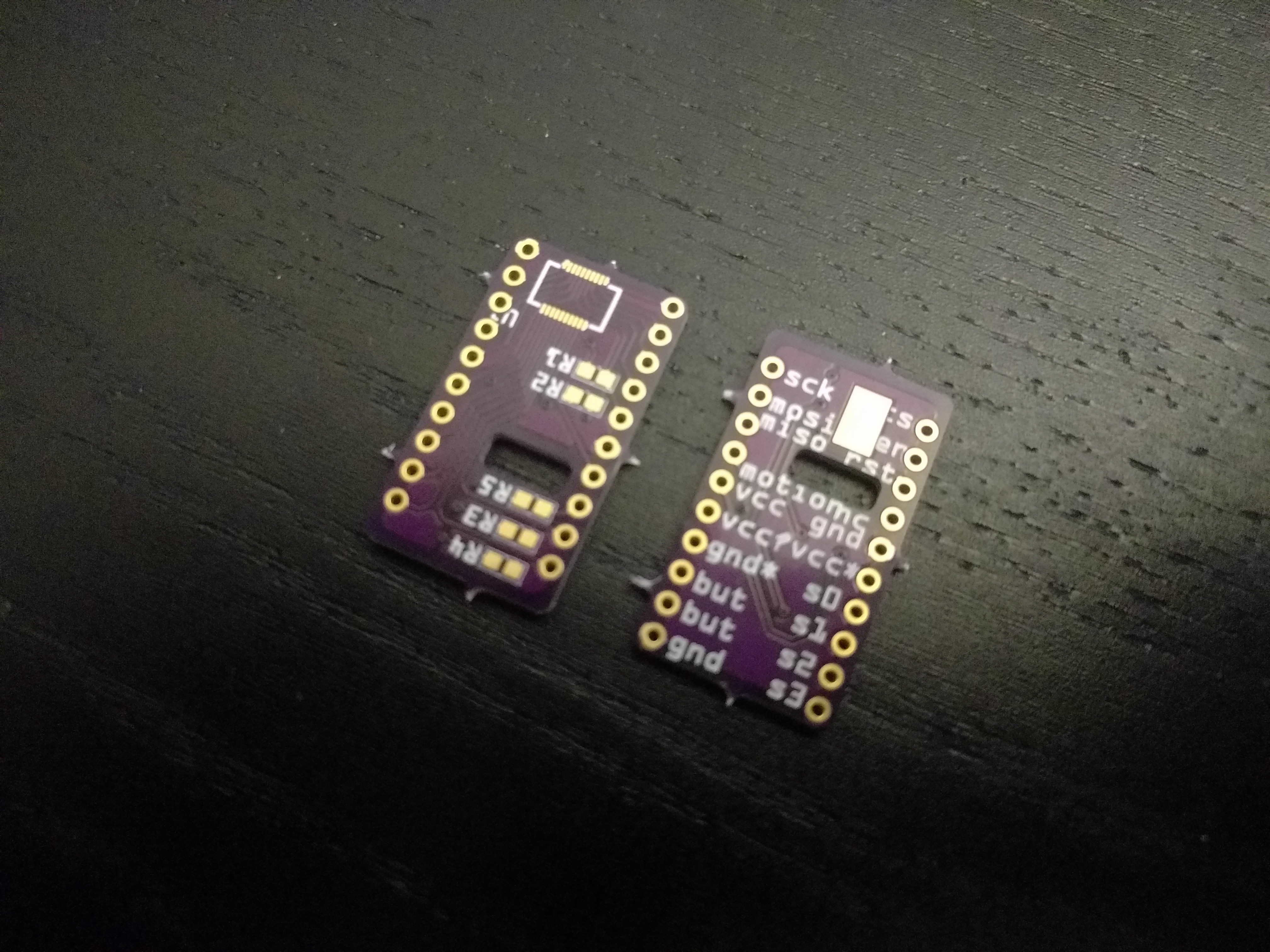
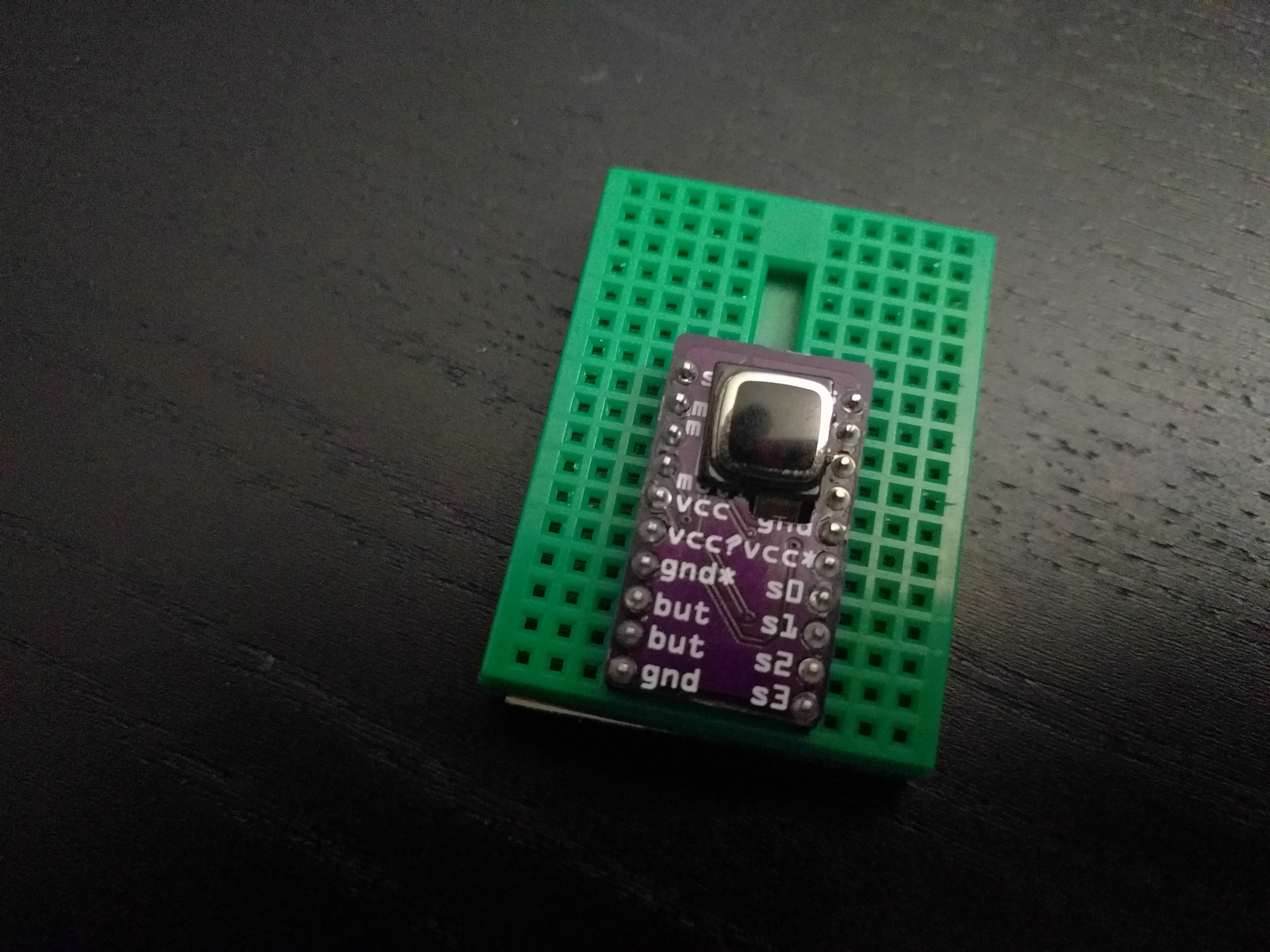
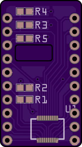
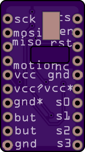
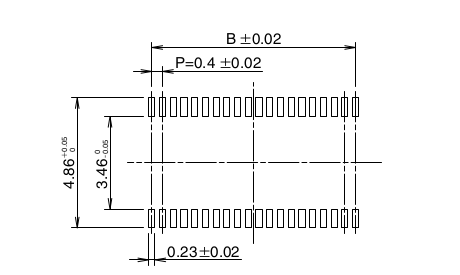
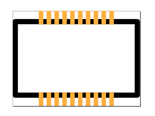
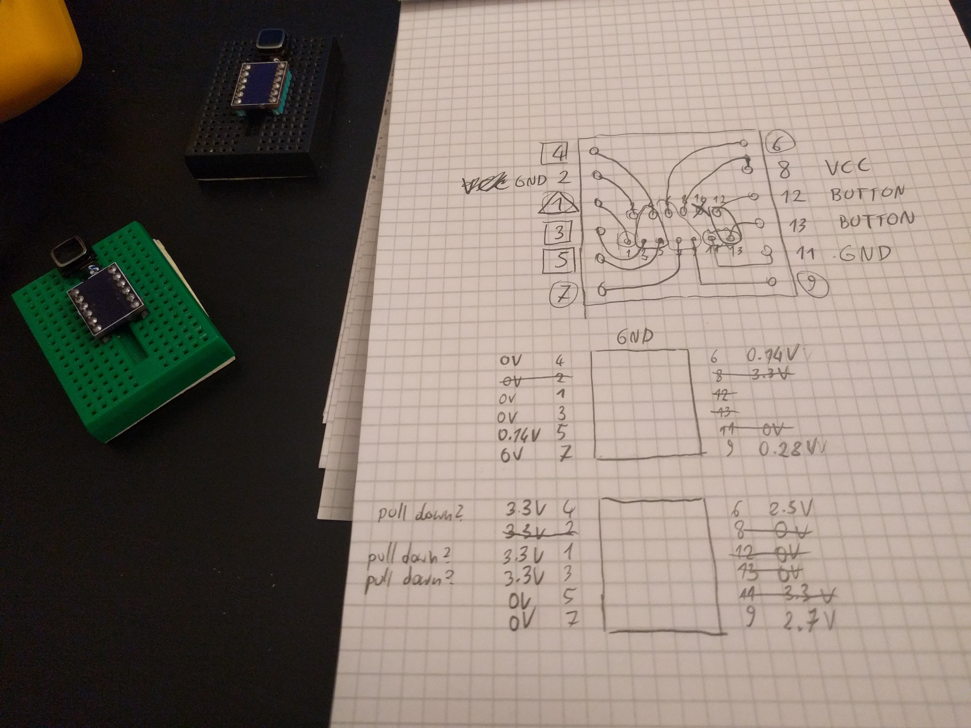
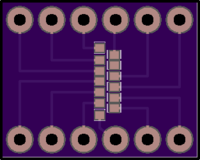
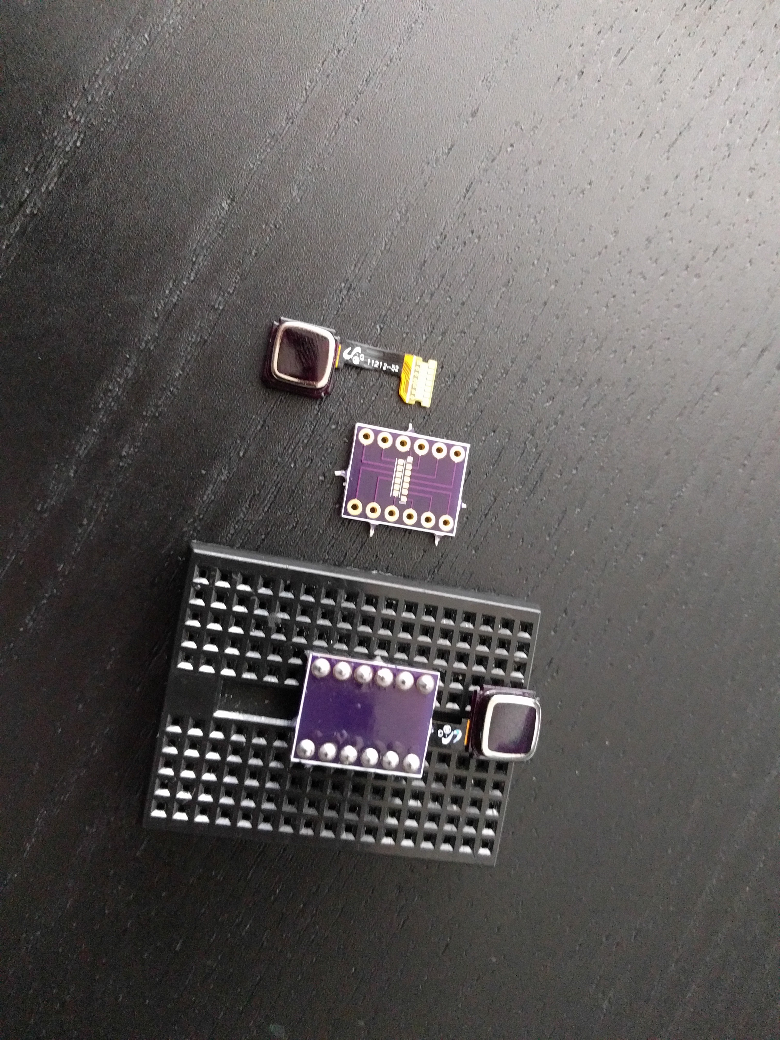
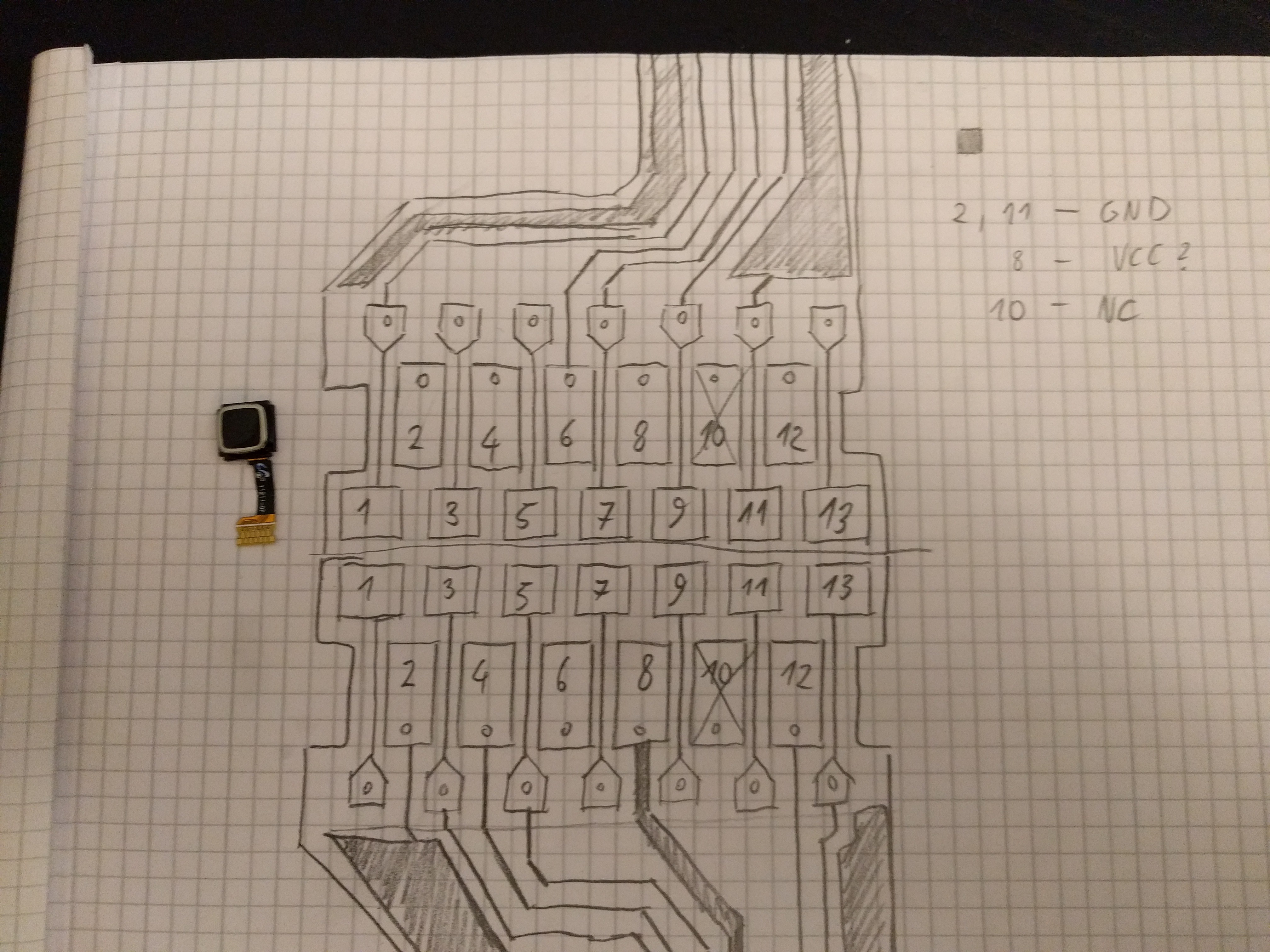
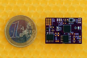
I decided to try and reverse-engineer one particular model of such a button, document it, and use it to build a module for my #Kamina Keyboard.

  • Prior Art

    deʃhipu11/25/2021 at 17:46 0 comments

    Apparently someone had the same idea as me, but also had the skill and energy to pull it off: https://github.com/vlukash/corne-trackpad

    I think I'm going to steal from that project.

    Looking at it, I see that I made a huge fundamental mistake, assuming a 2.8V device will work just fine with 3.3V. Turns out those optic sensors are very particular about their voltages, so time to invest in level shifters.

  • Another Failure

    deʃhipu08/22/2021 at 19:26 0 comments

    I finally had the time to try my new breakout. I was putting it off because deep inside I felt there is no chance it can work with the horribly inconsistent schematic and pinout I based this on. And sure enough, it doesn't. I wrote a very simple program to test it:

    import board
    import digitalio
    import time
    
    rst = digitalio.DigitalInOut(board.A4)
    rst.switch_to_output(value=False)
    
    cs = digitalio.DigitalInOut(board.A5)
    cs.switch_to_output(value=False)
    
    spi = board.SPI()
    
    spi.try_lock()
    
    buffer = bytearray(1)
    while True:
        spi.write(b"\x00")
        spi.readinto(buffer)
        print(buffer)
        time.sleep(1)

    This should, in theory, print a string of \x0d on the screen. But of course all it prints are \x00. I tried some combinations of pulling down or up various pins that were ambiguous in the schematic that was posted, but I didn't manage to make it return anything else than \x00 or \xff.

    I might try some more experimenting with it still, but for now it's a huge disappointment.

  • Second PCB

    deʃhipu07/18/2021 at 22:12 0 comments

    The PCB breakout for the 8350 sensor arrived from @oshpark and as always it looks great:

    Unfortunately I miscalculated the distance between the socket and the slot, not taking into consideration the thickness of the PCB, so I had to use a file to make the slot a bit bigger:

    That is fine, because this breakout is just for experimenting — the final one will have correct dimensions and only the pins that are needed.

    I have everything soldered up and prepared, but I didn't yet have time to actually try this sensor yet — hopefully I can do it tomorrow.

  • Another Breakout

    deʃhipu06/24/2021 at 15:47 0 comments

    I spent a little bit of time today to design another breakout PCB, this time for the Blackberry 8350 button:

    I took the labels from that pinout published it the Arduino forum, but comparing it with the schematic also published there, it seems to be a bit fishy... For example, a pin marked as "gnd" on the pinout is pulled-down to gnd with a 200k

    This is also an experiment with physical layout of the board — there is a cutout in the PCB where the flex cable is going through, and a pad where the button will be, so that I can put a drop of solder there, to provide the necessary raised bump for the tact switch on the back.

    I'm also not sure whether I should add a voltage regulator and some voltage dividers — the forum post says 2.85V, but I don't actually know if it will work with 3.3V as well. The mouse sensors, which are supposed to be similar, run on 3.3V.

  • A New Plan

    deʃhipu06/24/2021 at 09:21 0 comments

    I tried to fix the connection between the flex PCB and the PCB, but it looks hopeless. I ended up ripping the pad off of one of the sensors. I think I need to re-think this.

    At this point, the easiest way forward seems to be to find the correct mezzanine connector for the Blackberry 8520 sensor — after all I even have a ready pinout for it! After some searching, it seems that something called DF30FB-20DS-0.4V should fit. I have ordered it, and we will see.

    In the mean time, I can prepare the footprint for it. The datasheet gives me a recommended pattern:

    Replicating this in Inkscape just takes a few moments:

    Now I just need to quickly design a PCB, and hopefully the connector and the PCB will both arrive at about the same time.

  • Power On

    deʃhipu06/23/2021 at 20:41 0 comments

    I was right about motivation from the updating of the project logs — right after I finished the last log, I decided to continue the exploration. So I took a piece of paper and I figured out which pin is connected to which pad:

    Then I connected the power to the VCC and GND pins, and measured the voltages against GND and against VCC on all pins, hoping that maybe this will give me some insights. The results are a little bit weird, so I decided to also try and measure the resistance between all pins and VCC and GND — of course with the power disconnected.

    The results were even stranger, so I repeated the same procedure with the second module, and got completely different results.

    My suspicion so far is that it's indeed very hard to get those pads soldered properly without shorts and breaks, and that I did a poor job with it.

  • Breakout

    deʃhipu06/23/2021 at 19:33 0 comments

    I quickly designed a very simple PCB breakout for the sensor — just the 12 pads that are connected to something, in random order. I made the pads slightly smaller than the ones on the flex PCB, to give myself some wiggle room. Then I ordered it from my go-to place for small boards: @oshpark.

    A few weeks later the boards arrived, and I soldered the sensors up. Turns out that soldering the flex PCB to a regular PCB is not so easy either — not as easy as drag-soldering displays, anyways. But I managed somehow:

    It even fits nicely on the mini-breadboard's flat part, so I can press the button! Next up is connecting all the wires and figuring out which is which. But here, my laziness backfired on me.

    You notice I didn't add any labels to the pins, and that they are broken out in a rather random order — whatever was easiest to route. I didn't have much energy back then, and I wanted to order those PCBs fast, so they would arrive earlier. I was hoping I will have more energy when the PCBs arrived, and can work around all the corners I cut.

    That didn't happen. I still need to glue a piece of paper to this board, label the pins, and try connecting them. Motivation is a fickle beast, and when I'm facing the prospect of a boring chore, such as trying out all possible pin combinations in the hope that one of them will finally work, my energy levels drop dramatically. I should have foreseen that, but the future always looks so good from back there.

    I decided to document this project and write those logs in the hope that it will motivate me to continue this. Will it? Well, we will see shortly, I suppose.

  • My Way

    deʃhipu06/23/2021 at 19:21 0 comments

    I decided that the sensor from a Blackberry 8520 has too fancy a connector, which would be difficult to source and to solder (with a 0.4mm pitch), so I looked at other similar sensors, and picked one from a Blackberry 9300. Originally it no doubt uses even fancier connector, but the sensor-side is just a piece of flex PCB with a bunch of pads on it — something that should be easy enough to solder directly to a PCB.

    So I got a pair of those, and got to work on them. The initial probing yielded me this:

    GND was easy to find, because it is connected with the ground fill on the flex PCB. The VCC was easy too, because it's the only track that is thicker than all the others. And finally pin 10 is not connected, which was easy to figure out by visual inspection — there are no traces going to it!

    Next, I got out an ohmmeter and found that pins 12 and 13 are connected to the tact switch on the bottom of the sensor. That is 6 out of 13 pins out of the way, 7 more left to go.

    Those remaining pins should be, if this sensor is similar to the other one, CS, SCK, MISO, MOSI, RESET, SHUTDOWN, and INTERRUPT (aka MOVEMENT). There are lots of possible combinations here, but if you look carefully at the traces, you will note that they are in fact bundled in two distinct groups.  My bet is that one of those groups is going to be all the SPI pins, and the other — the rest.

    Well, we won't know until we try. So the next step was soldering some wires to those pads, to connect them to a microcontroller and try sending some signals. Unfortunately, it turns out that the pads are way to small to do that, and soldering to a flex PCB is way too hard. After a few failed attempts, I decided to make a custom PCB with a footprint matching those pads. That delays the project a little bit.

  • Prior Art

    deʃhipu06/22/2021 at 17:46 0 comments

    There is one other attempt at using this kind of sensors that I know of. It's an old post on the Arduino forum, together with a YouTube video with the demonstration, and a few missing images: https://forum.arduino.cc/t/blackberry-joystick-navigation-key-hack/61454/12

    In this case a button from Blackberry 8520 was used, which has a very fancy connector, similar to those used sometimes for displays. The sensor itself seems to use SPI protocol and registers very similar to mouse sensors — which makes a lot of sense, since it is basically the same sensor as in an optical mouse, only with different optics and physical shape.

View all 9 project logs

Enjoy this project?

Share

Discussions

lsit2590 wrote 02/04/2022 at 11:13 point

What a wonderful idea and I would like to suggest you the option of best topre keyboards you can click here and learn about this keyboard.

  Are you sure? yes | no

deʃhipu wrote 09/18/2021 at 14:48 point

Thank you, that looks much cleaner to what I have found so far. I will give it another try.

  Are you sure? yes | no

agilum wrote 09/18/2021 at 17:06 point

I am sure You will succeed…

  Are you sure? yes | no

Falkenad wrote 06/22/2021 at 19:21 point

The 8520 sensor appears to be the same sensor that the fellow who made the Thumbmouse project (previously documented here) eventually used. There seems to be some work in Zephyr for an SPI driver, but not sure if it went anywhere and that project wasn't exactly well documented - whoever I know that guy is also on the various Discords so maybe he'd have some input if needed regarding making an SPI driver for it work as the ZMK folks seem to have picked up on it. 

  Are you sure? yes | no

deʃhipu wrote 06/22/2021 at 19:55 point

The SPI driver shouldn't be a problem — as I mentioned, the registers are the same as in mouse sensors. The main problem I have, as I will write more about soon, is the pinout of the sensor I want to use — one from Blackberry 9300 — because it should be much easier to solder to a PCB.

  Are you sure? yes | no

Falkenad wrote 06/22/2021 at 20:00 point

Is that a FPC connector, or would you solder directly to the board? If the latter, a mezzanine connector seems like it would still be a little easier to use.

  Are you sure? yes | no

deʃhipu wrote 06/22/2021 at 20:21 point

Easier for sure, but hard to source.

  Are you sure? yes | no

deʃhipu wrote 06/24/2021 at 09:12 point

Looks like you were right about the connectors, I need a new plan now.

  Are you sure? yes | no

Similar Projects

Does this project spark your interest?

Become a member to follow this project and never miss any updates