 agp.cooper
CP/M Boot Logic
One the things about CP/M is that upon reset the system boot from ROM. The ROM loads the CP/M operating system. For the i8085, reset starts at address 0x0000. In normal operation CP/M expects everything to be RAM. The zero page (0x0000 to 0x00FF) is used by CP/M and programs are loaded from 0x0100 up. And CP/M lives at the TOP of RAM.
Therefore some logic is needed to move the boot system ROM address to 0x0000 on system reset. After boot/reset the address logic needs to be set for access to normal RAM.
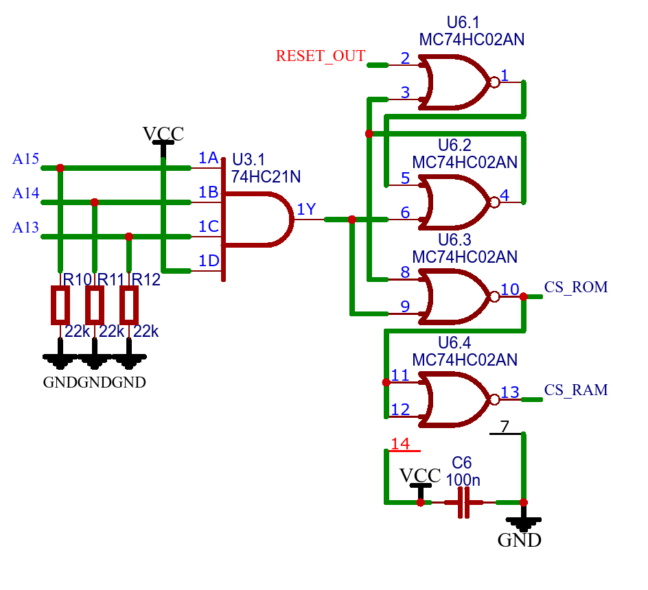
This can be done with a Set/Reset Latch using IC3 and IC6. On system reset, RESET_OUT set the latch, and A15, A14 and A13 reset the latch. Normally, the address of CS_ROM is 0xF800 to 0xFFFF (8kb) and the address of CS_RAM is 0x0000 to 0XF7FF (56kb). On system reset the latch is set and CS_ROM is set/locked low and CS_RAM is set/locked high. A high address (0xF800 to 0xFFFF) reset the latch to normal use.
One of the advantages of the system is that 8kb the ROM is visible above memory. This makes access to ROM fast. The down side is less RAM.
Other methods
Grant Searle uses I/O to set and reset the boot ROM. After boot he access the harddisk via I/O. Therefore his system has 64kb or RAM.
I am leaning towards Grant's banked memory approach, and using "port" (i.e. I/O or memory mapped) to access hardware.
I have already decoded 4x4 ports starting at 0x0040 (e.g. the UART).
But let us use baby sets!
AlanX
Discussions
Become a Hackaday.io Member
Create an account to leave a comment. Already have an account? Log In.