 Florian Baumgartner
Concept and Hardware-Design
Power supply with very low quiescent current
The main challenge was to design a power supply, that guarantees a long-lasting battery life, as well being enough powerful to light up all 31 RGB-LEDs at once.
A single AAA-Battery has a nominal voltage of around 1.5V. While discharging, the voltage drops under 0.9V at the end of its capacity. The SK6805, however, needs at least 4.3V to work properly (the datasheet recommends at least 3.5V, but then the colors shift to reddish quite significantly). One LED fully powered on (white) draws ca. 22mA, thus all LEDs together would consume around 650mA which is a lot of current!
To boost up the battery voltage to the desired 4.3V the TPS61200 has been used. The Low Input Voltage Synchronous Boost Converter is perfectly suited for this application. It can deliver up to 1.3A, although not very efficiently.
However, the rest of the cuiritry does not need such a "high" operating voltage. In Low-Power applications, the lower the operating voltage is, the smaller gets the power consumption of the device which results in a longer battery life. Therefore, operating voltages of 1.8V and below became a standard in the industry.
But there is a drawback at those low voltages. Maintaining high clock speeds of integrated circuits is getting substantially harder. Specially for older technologies like the AVR architecture used in the ATtiny-Family.
As you can see in the graph below (datasheet, p. 163), the maximum clock speed of the ATtiny45 is kind of linear to the operating voltage.
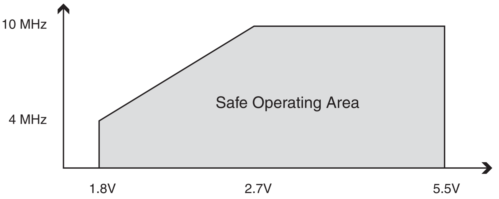
For generating the signals for the NeoPixels, a clock speed of at least 8 MHz is necessary. Thus, the ATtiny must be powered with at least 2.5V. While testing, I've noticed that sometimes the ATtiny has some difficulties to start up. As a result of this, I've increased the operating voltage to around 2.9V which didn't effect the power consumption significantly. To generate this specific voltage, a different DC-DC boost converter, has been used, with a very low quiescent current of only 5.5μA, namely the TPS61220.
This voltage rail is always powered on, if a battery is connected. That's why it's really important to put everything in sleep/power-down mode, when the device is not in use. Specifically the microcontroller and the temperature sensor which is a TMP116 (High-Accuracy, Low-Power and I²C-Compatible). The second DC-DC converter for the LEDs is turned off by the ATtiny to save even more power if nothing gets displayed.
I have measured a total current consumption in sleep mode of only 20μA at room temperature. This leads to a theoretical battery life of up to 6 years, considering a fully charged AAA Alkaline battery with a typical capacity of 1200mAh.
Reverse polarity protection for a single 1.5V Alkaline battery
As it might happen, someone puts in the battery the wrong direction which would result in potentially killing the entire electronics. To prevent this, a reverse polarity protection has been built in. A simple diode-circuit wouldn't be sufficient due to its substantial voltage drop. Thus, a more complex solution has to be found. This paper by Texas Instruments had some really useful information how to achieve this. E.g. this example schematic:
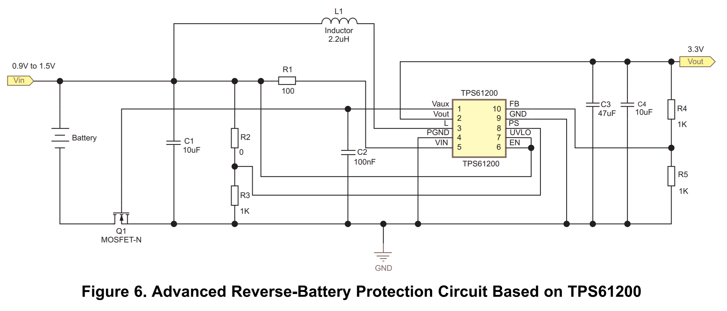
For this project, the circuit above has been modified slightly. For driving the gate of the MOSFET (FS8205), the internal 2.9V supply has been used. An additional low voltage schottky diode has been placed in parallel to the MOSFET, to help starting up the DC-DC converter.
Shock/Vibration sensor
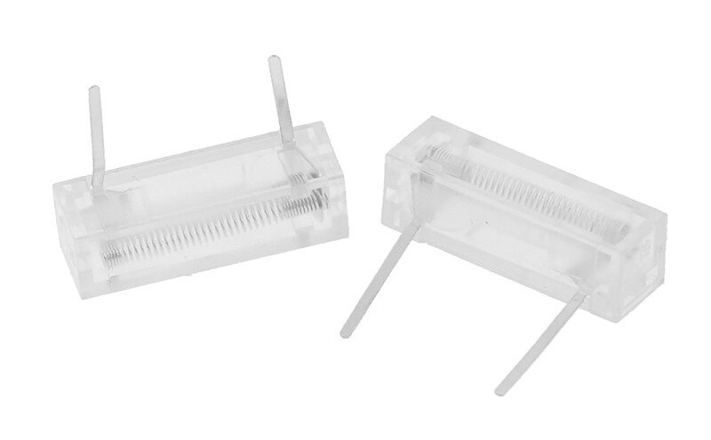
As a sensor that can be triggered by shaking the device, a cheap unbranded type has been used. It can be found by the part name: XXW-5818. I couldn't find any datasheet of it, but it really works great! Most importantly, it must be a "normally open" type, that guarantees no leakage current, when it's untriggered.
PCB-Design and Manufacturing
All SMD components are placed on top side of the PCB. This makes the manufacturing process much easier and fulfills the requirements of the JLC-PCB assembly service, which has been used in this project.
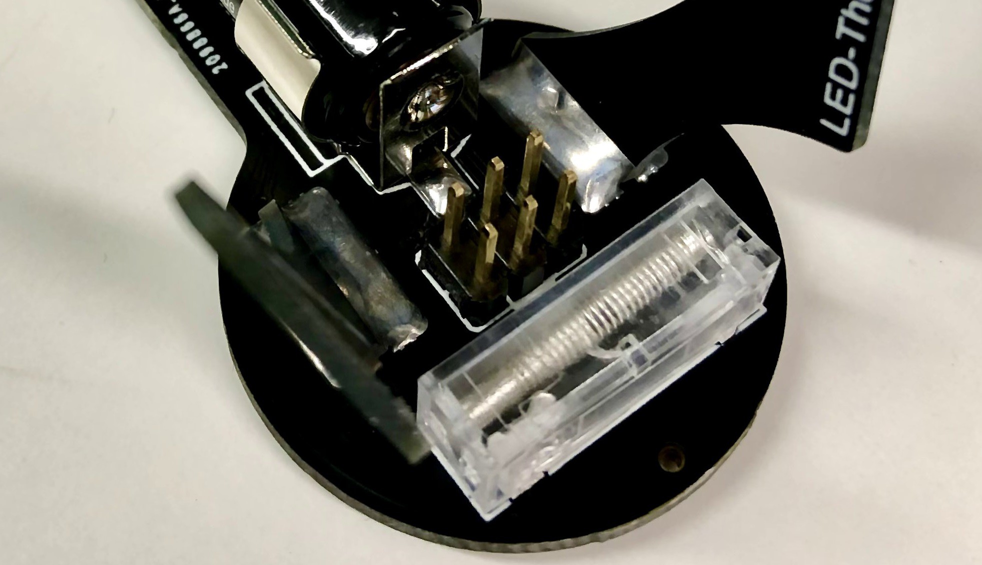
Only the vibration sensor and the pin header for connecting the ICSP AVR-Programmer ar through hole components and are mounted on the back side of the PCB. The Battery connectors are SMD as well, but have been hand soldered to the rear of the board.
As a stand, two small PCBs are used as feets. The have exposed pads on both sides and can be soldered to the back of the main PCB.
The main PCB has a thickness of 1.6mm and the feets are 1.2mm thick.
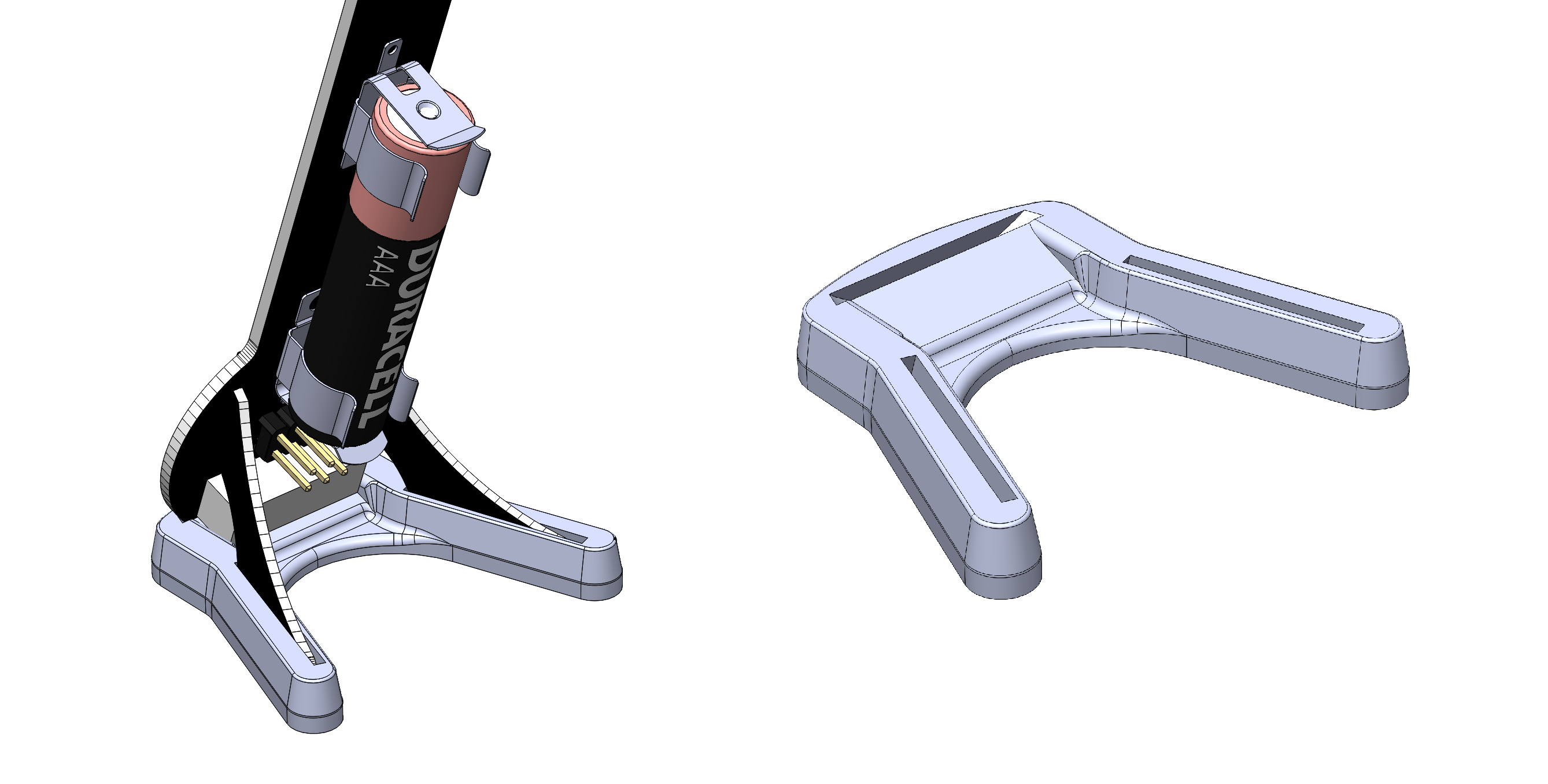
For getting the mounting angle right and ensure a correct placement, a 3D-Printed adapter socket has been made as you can see in the picture below.
A bit of flux helps soldering those pads. After cleaning and a bath in the ultrasonic cleaner they look quite pretty:
Firmware
The firmware has been made in the Arduino IDE with the ATtiny boards package installed. The core libraries can be downloaded from here. The sketch is not very optimized and uses therefore mostly of the program space on the ATtiny. No bootloader has been used to save some extra space.
The functionality is quite simple. If you shake the thermometer, the microcontroller wakes up and measures the temperature. Then it ramps up the LED bar in a designated color pattern to the current temperature in degree celsius. After 3.5s the bar ramps back down and the thermometer goes in sleep mode again. This linear ramping animation has a delay of 4ms between each LED.
Color Pattern Generator
For easier creating the look-up-table of color values used by the microcontroller, I've wrote a simple Python script. By assigning each color (red, green and blue) a mathematical function of the LED index, different kinds of color fades can be established. After some experimenting, I found a combination that looks best to me. The maximal brightness has been set to 22 (of max 255). The Python script can be downloaded below.
This script generates then a C/C++ style array that can be copied directly in the firmware code:
const uint8_t lut [LED_COUNT * 3] PROGMEM =
{
  0x00, 0x00, 0x16,
  0x00, 0x01, 0x13,
  0x00, 0x02, 0x11,
  0x00, 0x04, 0x0F,
  0x00, 0x05, 0x0C,
  0x00, 0x07, 0x0A,
  0x00, 0x08, 0x07,
  0x00, 0x0A, 0x05,
  0x00, 0x0B, 0x02,
  0x00, 0x0D, 0x00,
  0x00, 0x0E, 0x00,
  0x00, 0x10, 0x00,
  0x02, 0x11, 0x00,
  0x03, 0x12, 0x00,
  0x04, 0x14, 0x00,
  0x06, 0x16, 0x00,
  0x07, 0x14, 0x00,
  0x09, 0x12, 0x00,
  0x0A, 0x11, 0x00,
  0x0C, 0x10, 0x00,
  0x0D, 0x0E, 0x00,
  0x0E, 0x0D, 0x00,
  0x10, 0x0B, 0x00,
  0x11, 0x0A, 0x00,
  0x13, 0x08, 0x00,
  0x14, 0x07, 0x00,
  0x16, 0x05, 0x00,
  0x16, 0x04, 0x00,
  0x16, 0x02, 0x00,
  0x16, 0x01, 0x00,
  0x16, 0x00, 0x00,
};