 Open Green Energy
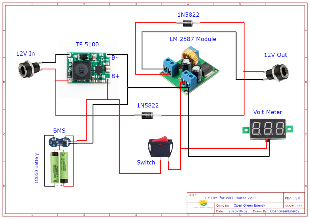
How the Circuit Work?
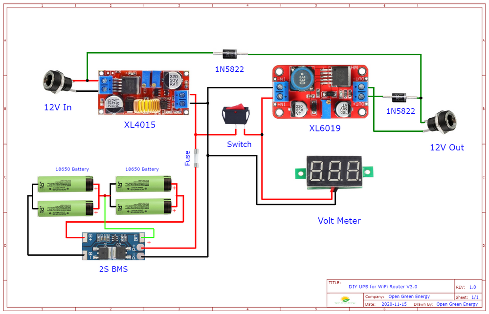
The working of the circuit is very simple, in normal condition, power from the mains is drawn by a 12V DC adapter to charge the 2x 18650 batteries and to provide power to the router. When the mains power fails, the stored energy in the battery is used to power up the router. The voltmeter display is used to display the battery voltage level. The two diodes 1N5822 are used to block the reverse current flow.
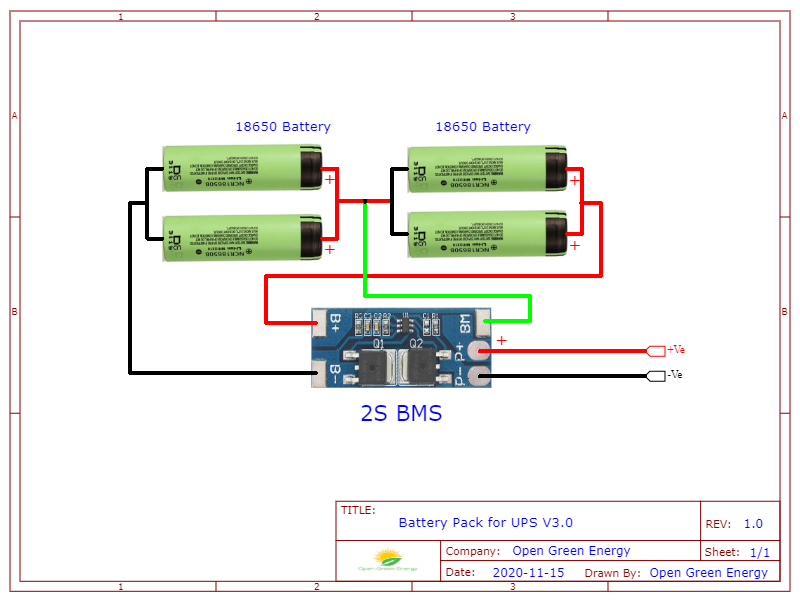
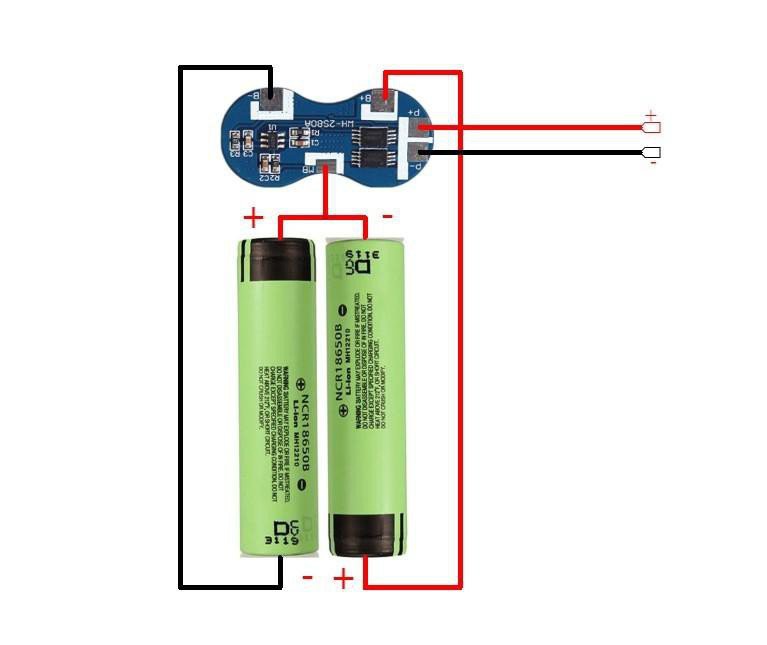
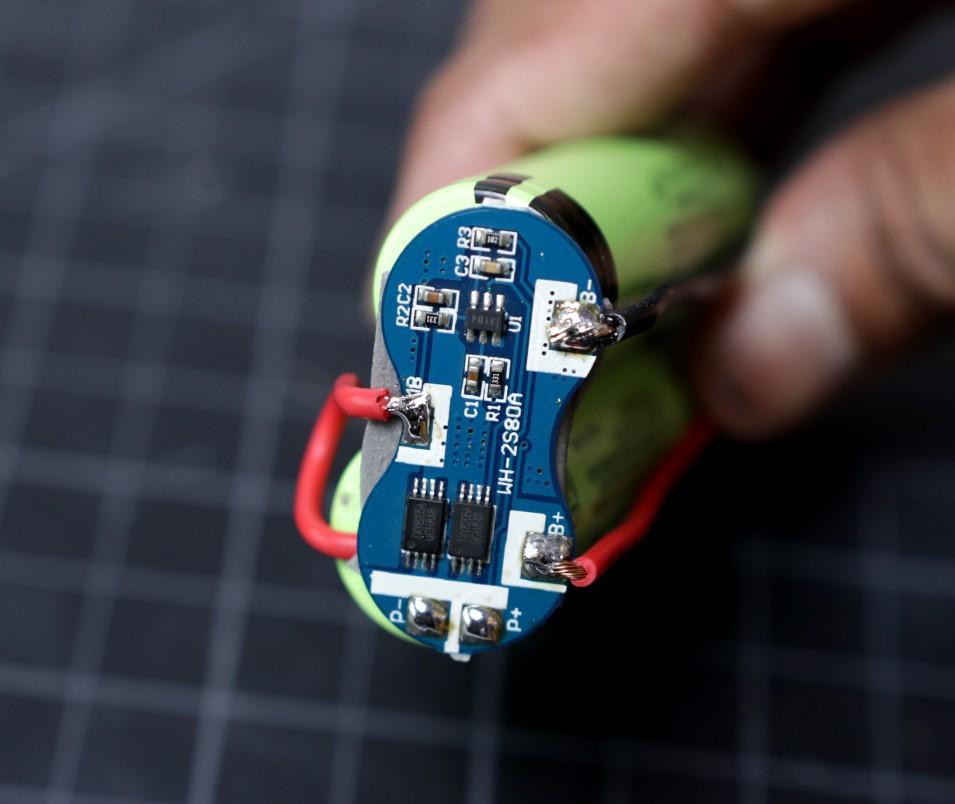
In the schematic diagram, the two18650 batteries are connected in series and then they are connected to a 2S BMS board for protection during the charging and discharging.
The positive terminal input DC jack is connected to the positive terminal of the output DC jack through a Schottky diode ( 1N5822 ).
The 12V input power from the DC adapter is connected to the input terminal of the TP5100 module through a 5.5mm DC Jack. The output terminal of the TP5100 charging module is connected to the battery pack.
The battery positive terminal is connected to the boost converter LM2587 IN+ terminal through a rocker switch and the negative terminal is directly connected to the boost converter IN- terminal.
The boost converter LM2587 Out+ terminal is connected to the positive terminal of the output DC Jack through a Schottky diode ( 1N5822 ) and the Out- terminal is connected directly to the negative terminal of the DC jack.
The voltmeter positive terminal is connected to boost converter IN+ and the negative terminal is connected to IN-.
Disclaimer: Please note that you are working on a Li-Ion battery which is potentially very hazardous. I cannot be held responsible for any loss of property, damage, or loss of life if it comes to that. This tutorial is written for those who have ample knowledge of rechargeable lithium-ion technology. Please do not attempt this if you are a novice. Stay Safe.


 Enki
Enki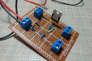
 Taste The Code
 Jack Steiger
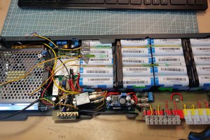
Hi there, living in South Africa, daily power outages (called "Load Shedding") is a part of life.
Would adding a 2nd 12V output (1 x Mikrotik Router & 1 x Huawei ONT) affect the duration it will last?