First of all: this project aims to achieve a simple, cheap and easy to build HF RTX. It is not about performance. It is a great way to experiment current day MCUs, and their toolchains.
Nonetheless it is quite good for receiving SSB, AM and CW on the ham bands, broadcast stations and HF services, all of this with an MCU, two bipolar transistors and a few passive components. Transmitting, 4 W CW only, requires one IC and two power MOSFETS .
Disclaimer: in most of the countries a ham license is required for transmitting, and there are limitations for RX too. Output signal quality, like harmonic content and spurious signal, was never tested. So please comply with the norms of your country. You are on your own, I am not a lawyer. There is also some chance of damage to the USB connected phone. You have been warned, I take no responsibility for anything.
I don’t possess the instruments needed to provide some numbers about the performance. The trade-offs that are implicit in this simple architecture will be shown.
The core of the RTX is the I2PHD’s receiver that you can find, modified for an open toolchain, in my github page. As always, have a look at the original PDF for ARM Radio at weaksignals.com.
Since the original receiver, ARM M4 based, new MCUs based on the M7 architecture appeared.
In particular, STM32H750 sports ADCs that can achieve about 9.5 Msps, and can be overclocked up to 600 MHz. At least in the three samples I tested. YMMV but I feel all of them are stable at this clock speed, at least within common temperature and power supply conditions.
This project started during the first wave of the pandemic, when I had more time than now. The idea was to have a first version of the PCB, to test different design choices, then design a final PCB. As you have already imagined, I’m still at the first release, partly because of the components shortage.
This is what I have right now:
- Power supply: everybody has a mobile phone and power is drawn from its USB connector. For transmitting, I measured 4W output power, but the USB cable from the phone is not enough. A second USB cable, connected to a power bank or a power supply, is used. Of course it is possible to use a computer instead of the phone, and use two of its USB ports. The PCB can be populated with the voltage regulators needed in case power does not come from USB but from a 12 or 24V power supply. This is required to obtain a higher output power.
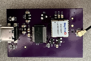
- Human interface: the phone, or PC, runs a serial terminal emulator. A minimal interface runs on the MCU. It shows frequency, signal strength, mode, etc. An ASCII art band scope is provided, cool but not particularly useful. There is a simple CW decoder. Radio can be controlled by the serial terminal’s keyboard, there is a rotary encoder for frequency selection, it is not strictly required. USB communication is done by the MCU acting as a Communication Class Device. No FTDI chips, USB goes straight to the MCU. Beware, the current PCB has the USB connector too far from the edge of the board and it is necessary to trim the cable connector.
- Most of the MCU’s pins are brought to through hole pads. It is a passable breakout board.
- There are several STM MCUs that share the same pinout but differ in Flash an RAM size. Now I’m using a STM32H750, the cheaper one. It was about 5 euros in quantity 1, when it was stocked. There are also newer components, like STM32H730, that are compatible , are faster and have a CORDIC peripheral that could be useful for LO generation.
- Two different RX topologies can be tested. The cheaper one is a quite typical direct sampling SDR. ADCs are limited to 9 MSPS and reception over 4.5 MHz is achieved by undersampling the signal. This means, for example, that a strong 3 MHz signal can be heard at 7.5 MHz, since the input band pass filter does not provide enough off band attenuation. One could mitigate this problem by having two selectable...
Read more »
 Stefan Wagner
 Marsupilami
 Nick Sayer
 rbtsco