 Jonathan
The Purpose of the MycoBox
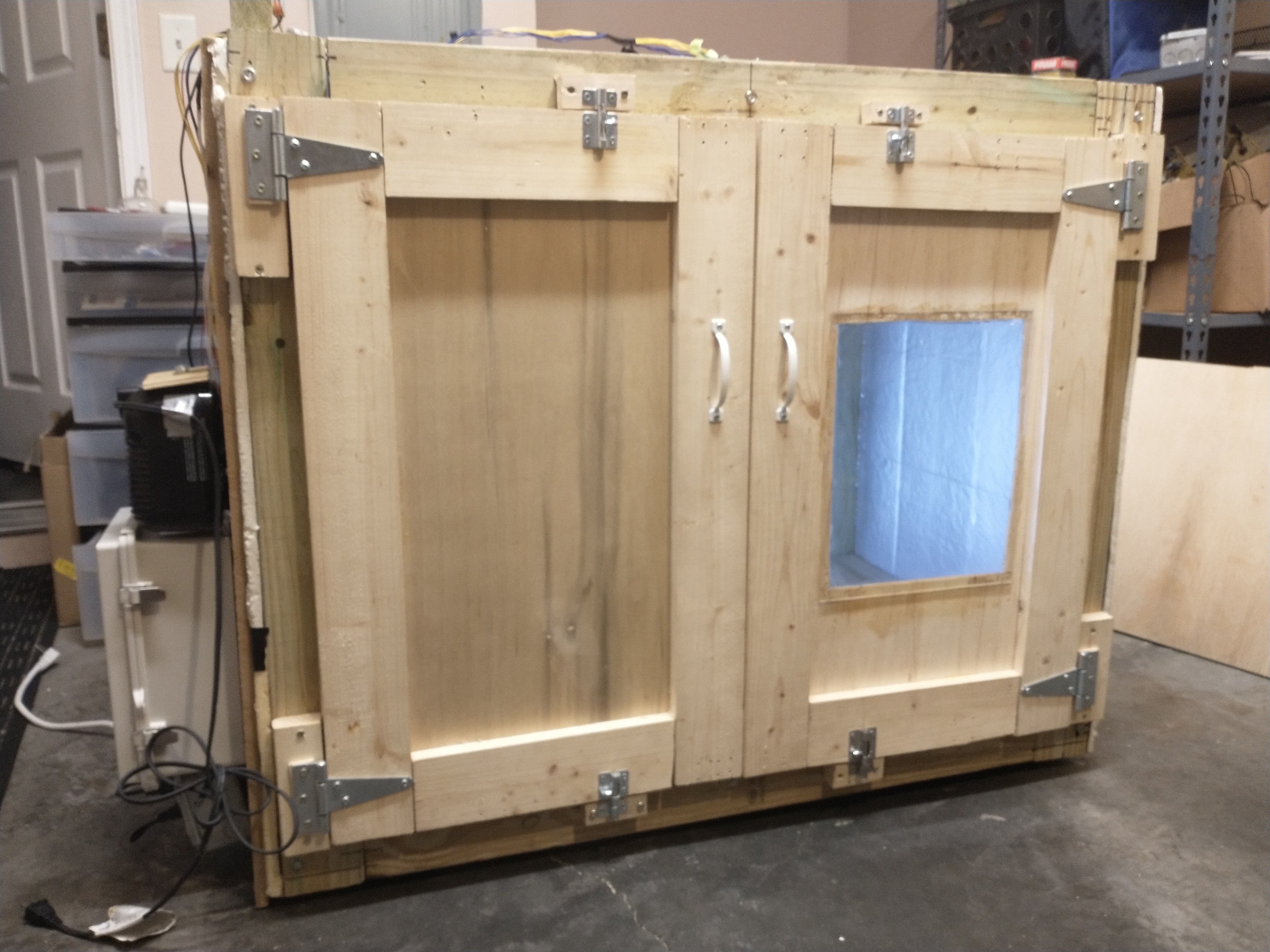
MycoBox is intended to be a software controlled chamber for taking the guesswork and manual maintenance out of growing mycelium and mushrooms. Growing mushrooms is a surprisingly common hobby around the world, partly because it can be done with very low-tech techniques and the results are often worth the effort. However, most people who have tried also know that it can be an extremely error prone and frustrating endeavor.
There are many factors to cultivating mushrooms, and “of the many factors...for producing successful crops, the misapplication of only one can result in poor fruiting or absolute failure” (Stamets 391 - 392). Furthermore, each stage of mushroom growth requires its own unique ideal environment; spawn running, primordia formation, and fruiting. As a cultivator goes through the process they must be adept at recognizing when and how to modify the environment for the continued healthy growth of their crop. This is a delicate game of balance, “as each factor is changed, secondary effects are seen. The skill of a mushroom cultivator is measured by the ability to compensate for fluctuations in this complex mosaic of variables” (Stamets 392).
This is where the MycoBox steps in, it is equipped with sensors and programmatic logic to handle this mosaic of variables, enabling it to become the skilled cultivator on behalf of the user. This opens the door for more people to become effective citizen mycologists, which I think is pretty important.
The Software:
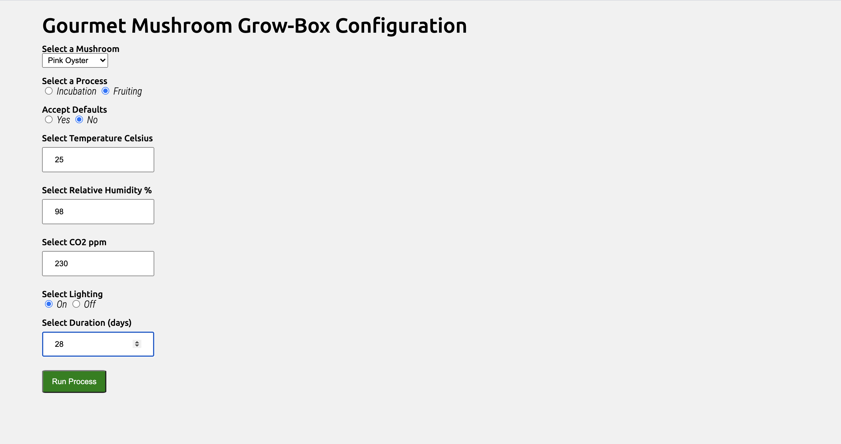
The above is an image of an early concept of the configuration page for starting a MycoBox session. The first field is a drop-down menu for selecting which mushroom will be grown during the session, and the second is an option to accept or reject the default configuration for the selected mushroom. This way, instead of manually deciding the environment configuration a beginner can select a default to get started. However, a more advanced user has the option to opt-out of the default configuration and define the variables for the environment that they would like to be maintained throughout the session.
This early concept is too limited in detail and doesn’t enable the level of control that I intend for the final version. First of all, this configuration confines a session to only incubation or fruiting, instead of allowing a user to define how the environment will progress with the mycelium through all three stages of growth; spawn running (incubation), primordia formation, and fruiting. The configuration is like the road map, or flight plan for the mycelium, and it is carried out by the environment manager (EM); which is the core program that physically reads and sets the environment via the sensors and actuators in the MycoBox. The environment manager is what makes the MycoBox a skilled cultivator, it automatically compensates for fluctuations in the variables defined by the configuration as it moves through the critical shift points of the three stages of growth. To illustrate what the configuration and environment manager must account for, I will walk through how the environmental variables must shift for each stage of growth.
Spawn Running
Spawn running is the period in which the vegetative mycelium hyphae branch out and grow throughout the substrate to form a very dense network that eventually engulfs all of the available resources.
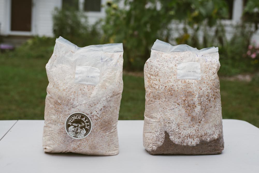
^ this is just an illustrative photo I found on the internet
This is the vegetative period of growth in which the hyphae release exoenzymes to digest and then ingest the available nutrients from the substrate. Moisture, carbon dioxide, and temperature are the most important variables for this period of growth. According to Paul Stamets’ book, Growing Gourmet and Medicinal Mushrooms, the moisture of the substrate at this stage should be between 60 to 75% for “strong and quick spawn running of mycelium” (Stamets 392); this can be maintained...
Read more »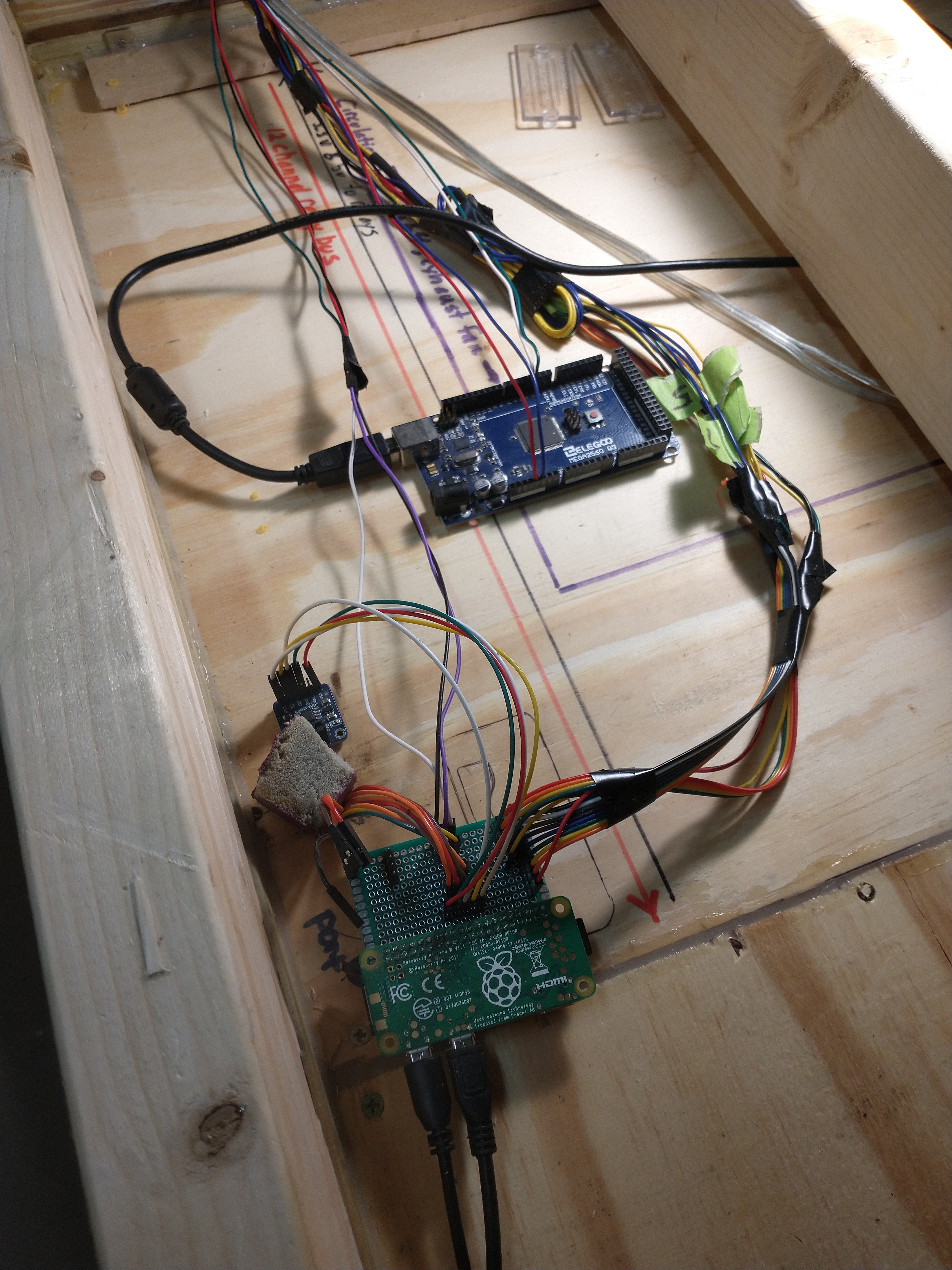


 Mild Lee Interested
 Jeff Thomas
 land-boards.com
 Andrew Shevchuk
Nice! I did something very similar with Arduino some years ago.