 Jonathan
Humidifier Test: 100% RH
Controlling Fan Speed:
To control the humidity, the humidifier fan throttles up or down to reduce or increase the amount of humidity released into the chamber. The Fan speed is controlled by a single channel AC phase control module (Dimmer), the dimmer is connected to an Arduino Mega2560 that receives serial commands from the Raspberry pi zero W. The phase control module uses a zero-point cross detector and a triac gate to track every single wave of the 60Hz AC entering the device. For each half of an AC wave the Arduino Mega sends a value indicating how long the triac gate should wait till allowing current to pass through to the device. The longer the wait the less power is output, if there's no wait at all the device will be running at full power.
In the below video I'm running the fan at a medium, low, and then high speed by changing the value returned from the Arduino Mega. The Humidity PID controller will send higher or lower command values to the humidifier fan as the process dynamically responds and eventually settles into the set-point (target) humidity. The medium command was 250, low was 300, and faster was 175; so you can see a smaller wait time correlates to more current and a faster fan.
To communicate with the dimmer module it was necessary to increase the amount of GPIO available to my Raspberry PI, So I have attached an Arduino Mega2560 via usb for serial communication. (The usb cable is wrapping around out of the picture)
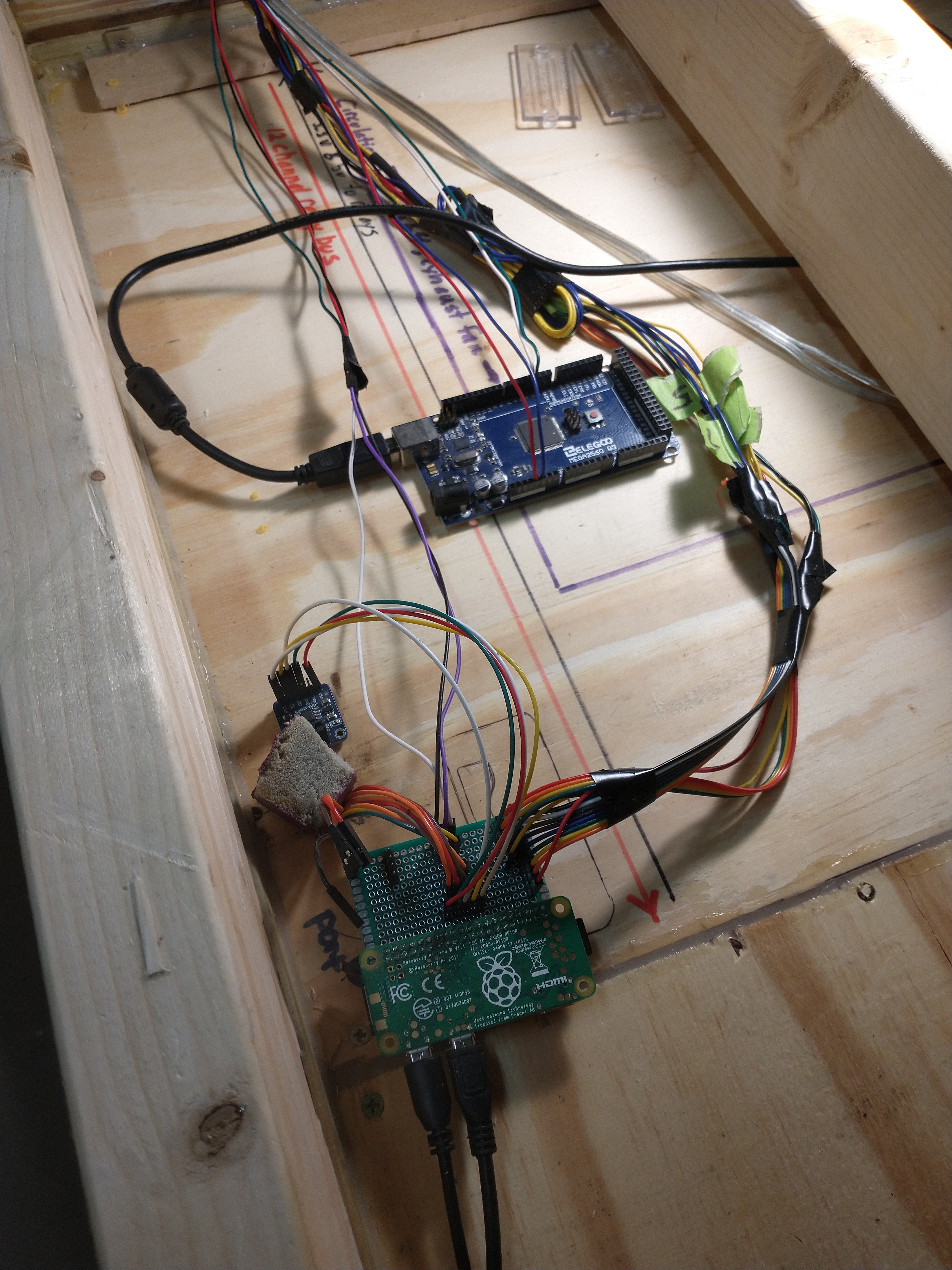
The raspberry pi will send serial commands to the Arduino Mega that correlate to each PID controller; e.g. "H 105", "I 200", "E 175", "CB 105", "CT 105". Each letter indicates which controller the command value is for; H = Humidifier, I = Intake Fan, E = Exhaust Fan, CB = Circulation Bottom Fan, CT = Circulation Top Fan. The value corresponds to how much current is being delivered to the actuator. I am considering also migrating all 4 of the sensors to the Arduino Mega as well, in hindsight I should have been using the raspberry pi to command the Arduino Mega for it's more expansive GPIO capabilities from the start. I will make another breakout board for the Arduino Mega, this way all of the sensors and AC phase controllers will be neatly on one board. I will leave the relay control tied directly to the Raspberry Pi, I've already built that and that feels like an appropriate use of the Raspberry Pi's GPIO.
Adding the AC Phase Controller to the Relay
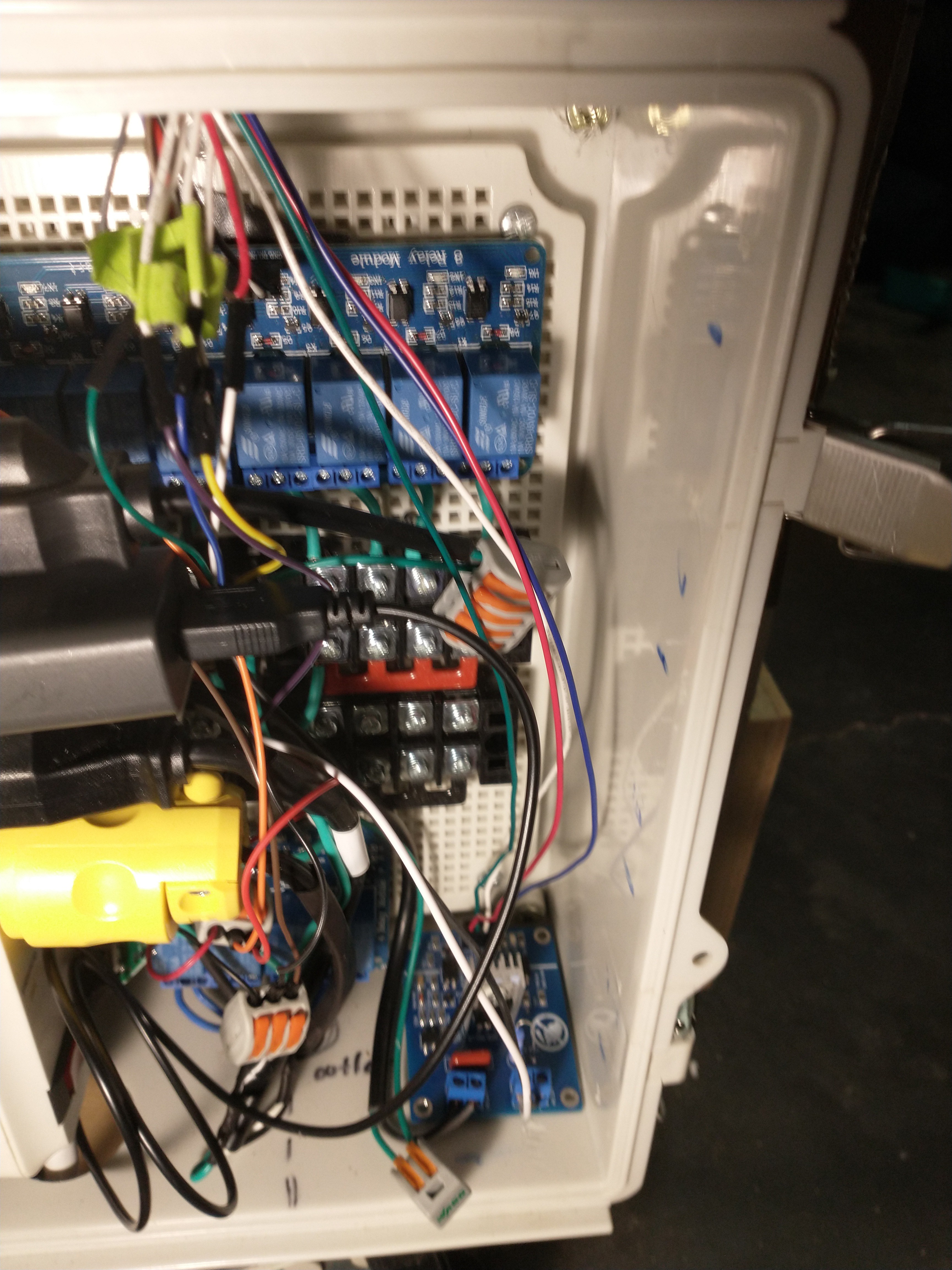
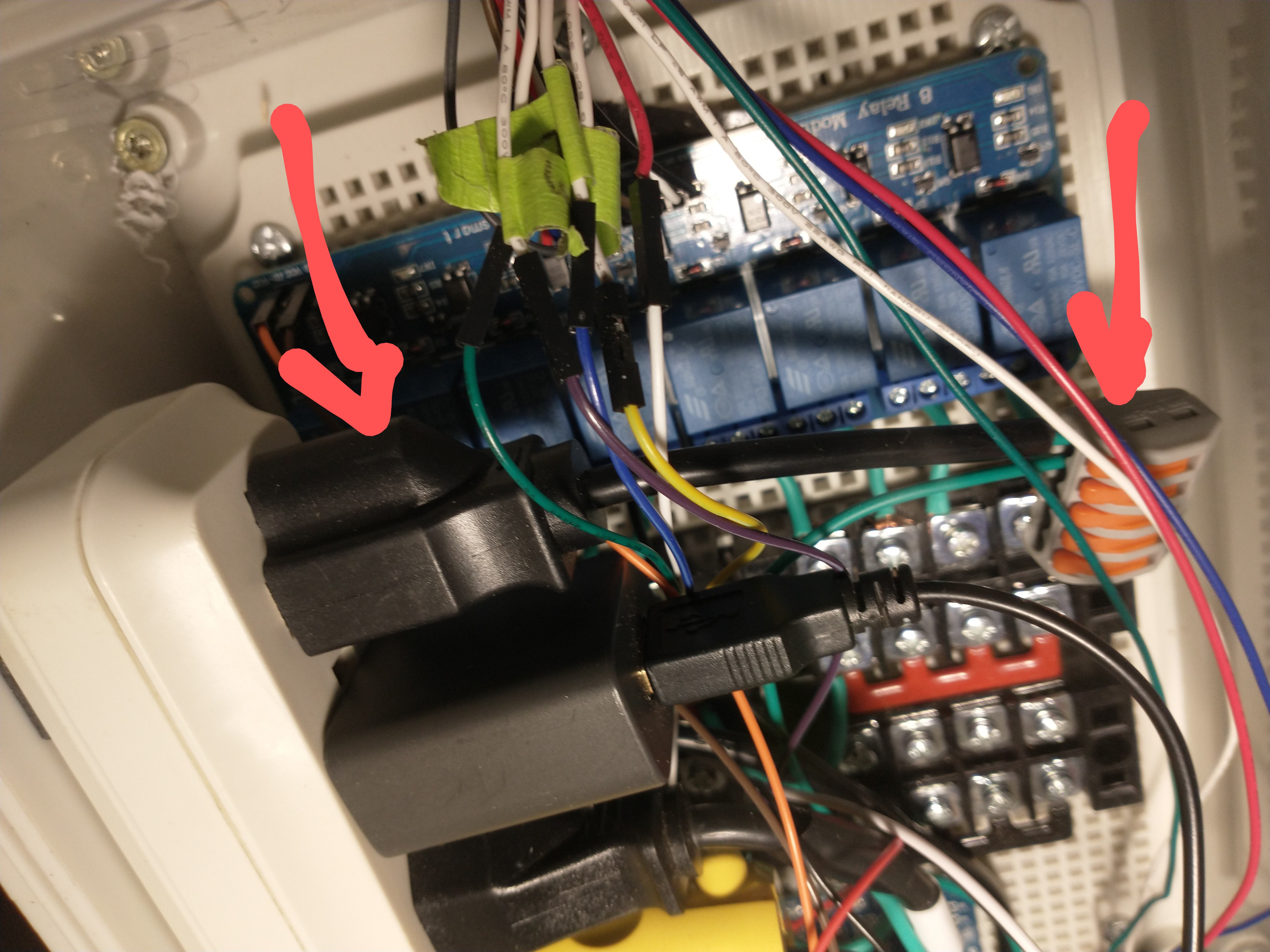
The blue board in the bottom right corner of the relay box is the controller I'm using for now. If you look at the right side of the box you'll see little blue markings where I was planning on including more of these modules. However I found a better option, an 8 channel AC Dimmer module, which is a single board and much cheaper and space efficient (however, before I found this amazing board on amazon I already regrettably ordered 6 boards from Ebay that are taking forever to get here and I can't cancel ). The red, white, blue, and green wires leading to the board are the digital control and power wires connected to the Arduino Mega.
Because The Fan has a ground cable, I used a lever connector to rejoin it and then passed it to another 5 channel lever connector attached to ground. You can see in the below photo the outlet with only it's ground connected to a 5 channel lever connector. I will attach the ground of any other AC phase controlled device to this grounding level connector as well.
The Humidifier Port
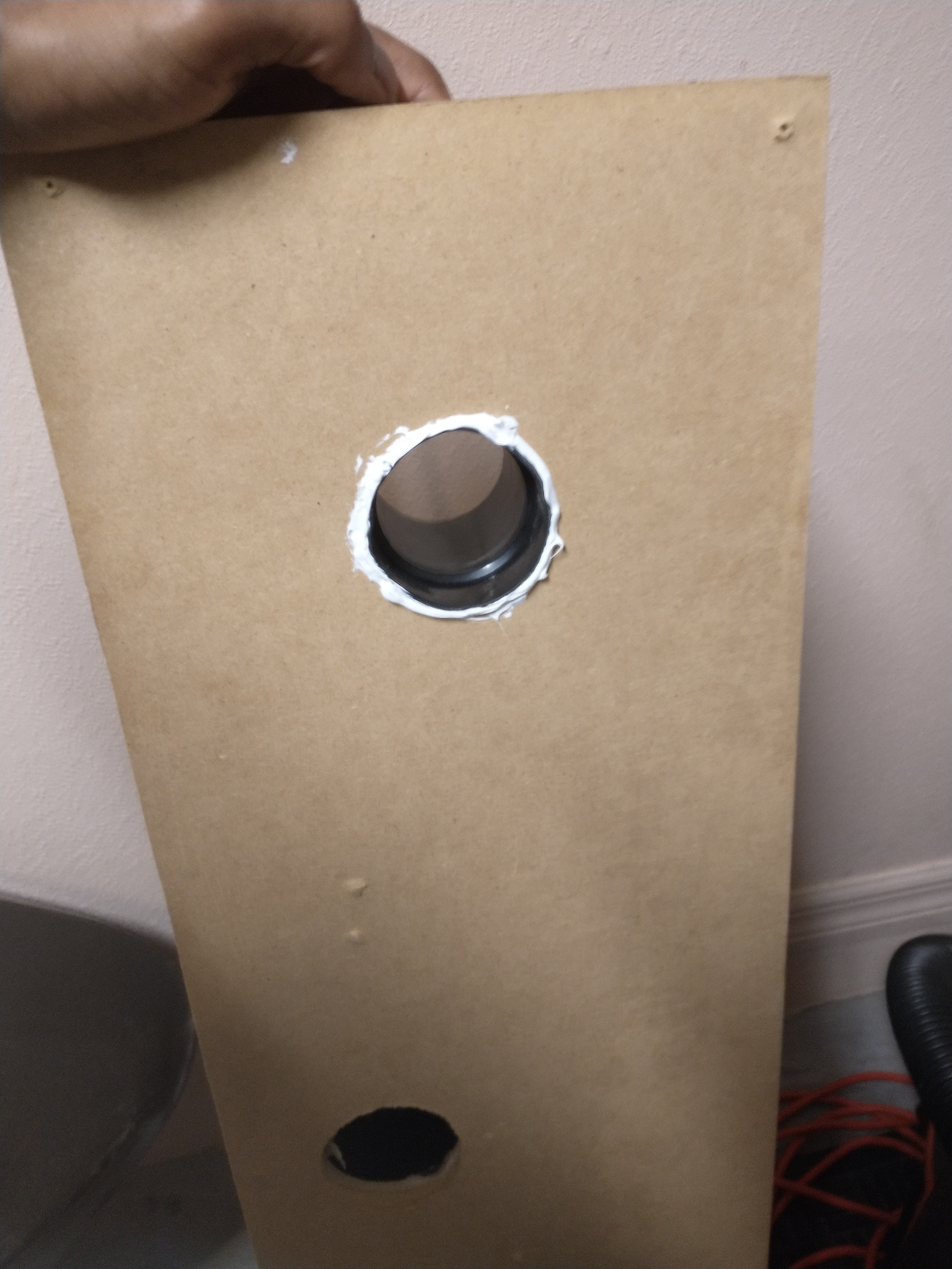
Fashioning a port for the Humidifier was simple enough, I cut a hole with my largest circular saw drill bit and then widened it a little bit more to fit a shop vacuum attachment. The humidifier hose is a shop vac hose that is secured to the bucket lid and clips on/off to the vacuum attachment. This way the humidifier can be attached or detached when needed. You can see the steps I took to creating the port below.
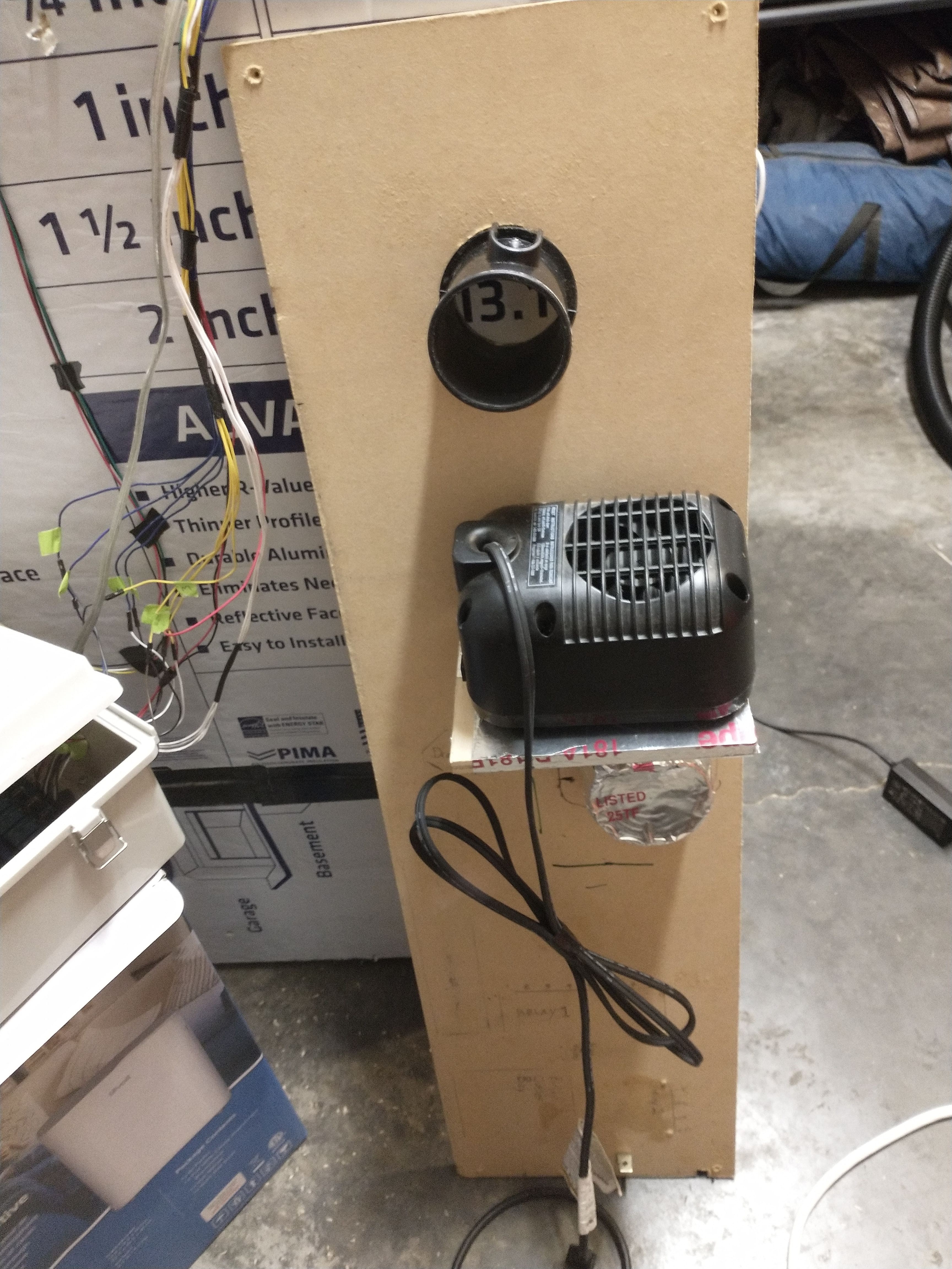
Here I've removed the wooden relay panel from the side of the mycobox to drill a hole for the humidifier port above the heater.
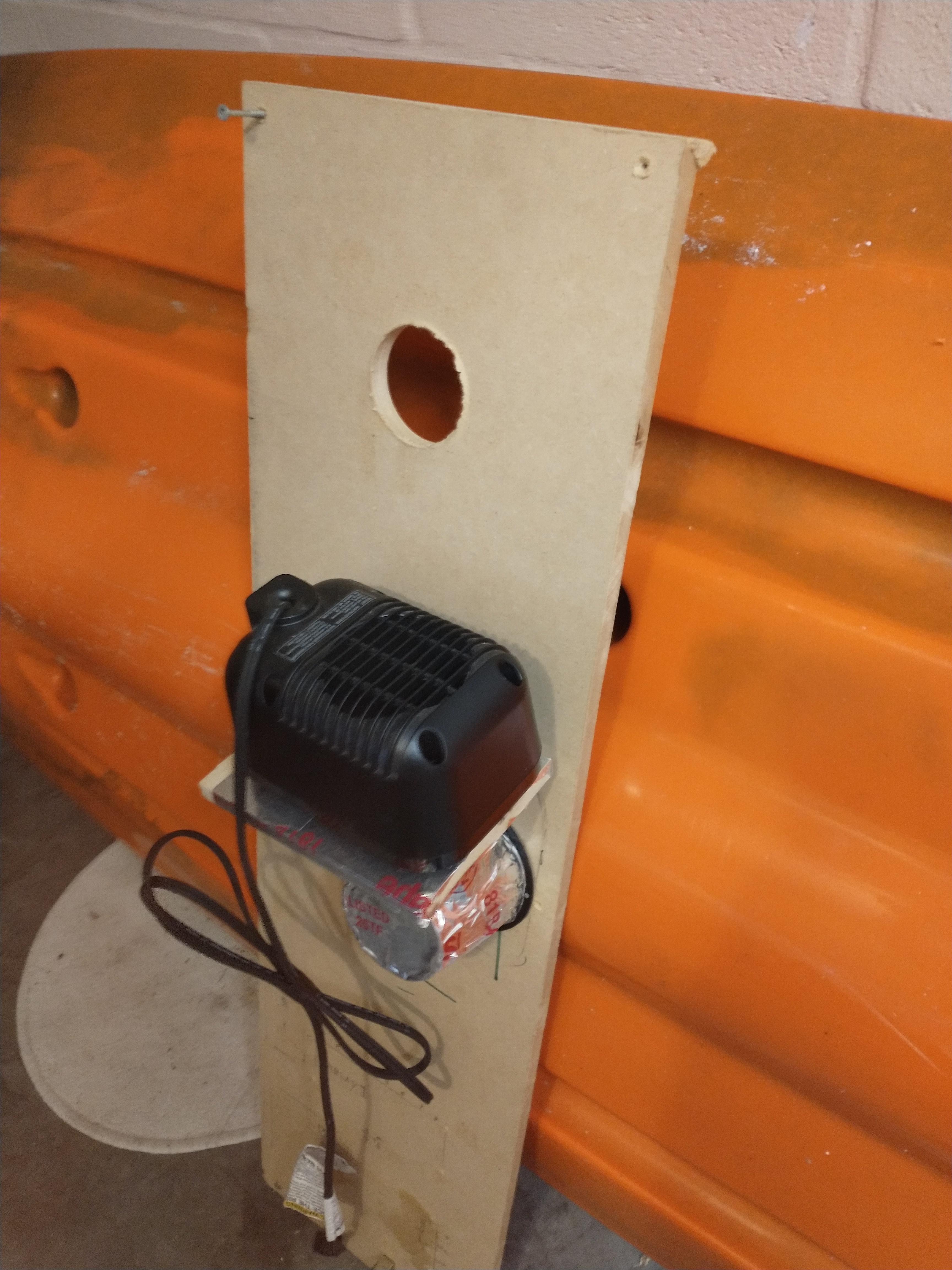
I expanded the hole a little bit more with a hand saw and then jammed this shop vac attachment into the hole to make a port. I sealed it with silicone caulk for a tight seal.
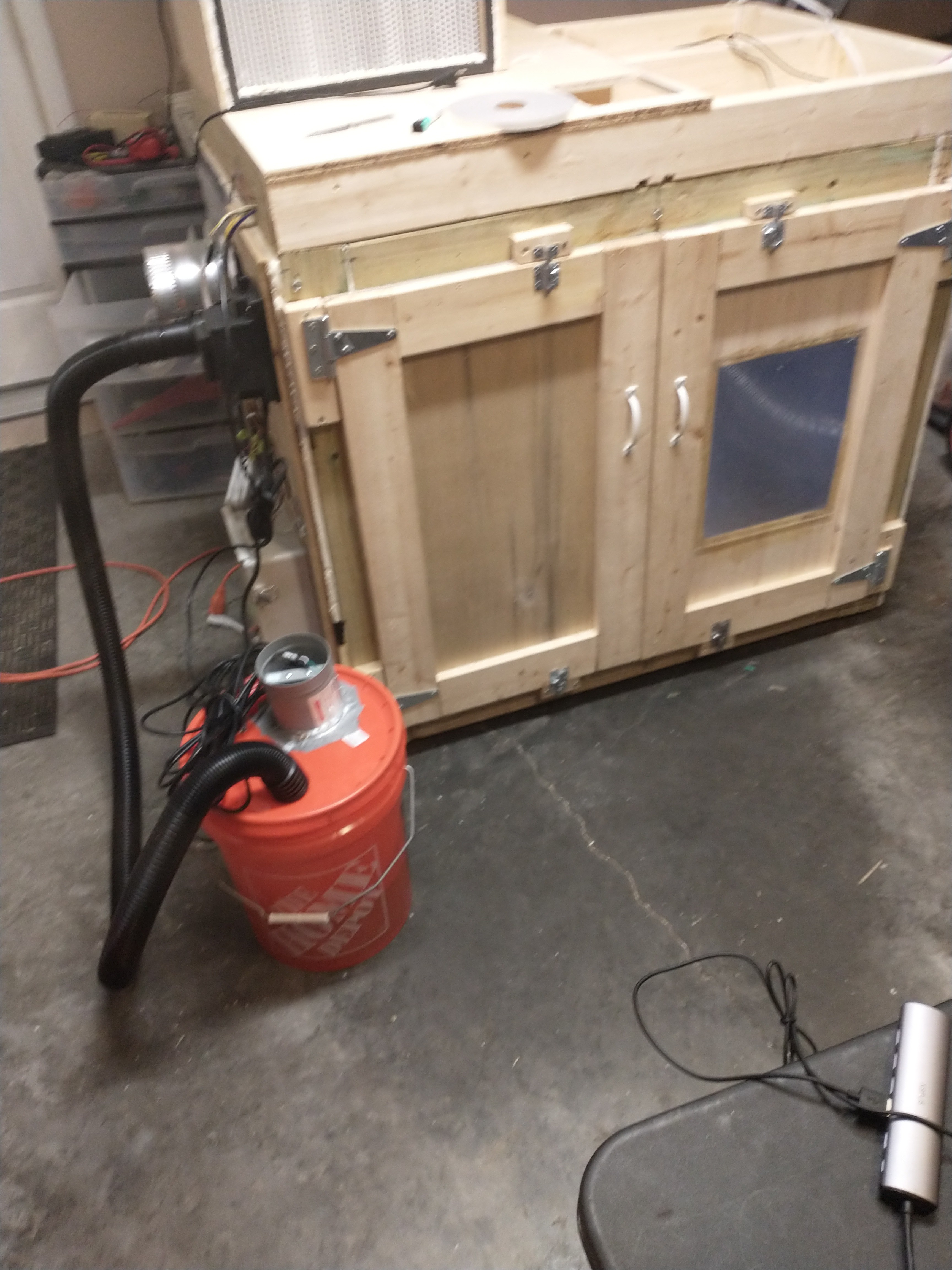
Making a Humidifier from a 5 Gallon Home Depot Bucket

You can see I've simply attached a booster fan pointing downwards to the lid of the bucket with a very secure mix of duct-tape and foil-tape 😅, this is the fan controlled by the AC phase controller. The shop vac hose fit like it was designed to snap into the lid after I cut a whole slightly smaller than the hose's diameter. And there is a tiny hole for the power cable to the mister leading out of the bucket (humidifier) as well. Soon I'll also be adding a water level sensor to the bucket, which will alert the user that the bucket needs more water; this is to protect the humidifier from damage.
There are a few other programatic safety thresholds in place for the humidifier, such as cutting off the mister or reducing its power when permissible to save power and prevent the mister from over heating.
Chamber View of the Running Humidifier
Next Steps:
The Humidifier hardware and circuit is set up and ready to be controlled by a PID controller, and in order to tune the controller correctly I will be running step tests, and bump tests today to form a First Order Plus Dead Time model that closely models the dynamic process of increasing and decreasing humidity in the chamber. I have attached a few scans of my notes on how I'm going about this modeling and design process. This website offers a very good breakdown, with details, of how to design and tune a custom PID controller, https://controlguru.com/.
Discussions
Become a Hackaday.io Member
Create an account to leave a comment. Already have an account? Log In.