 Alexander Williams
In v.2 I added M3 mounting holes to screw the ADXL directly to the PCB.
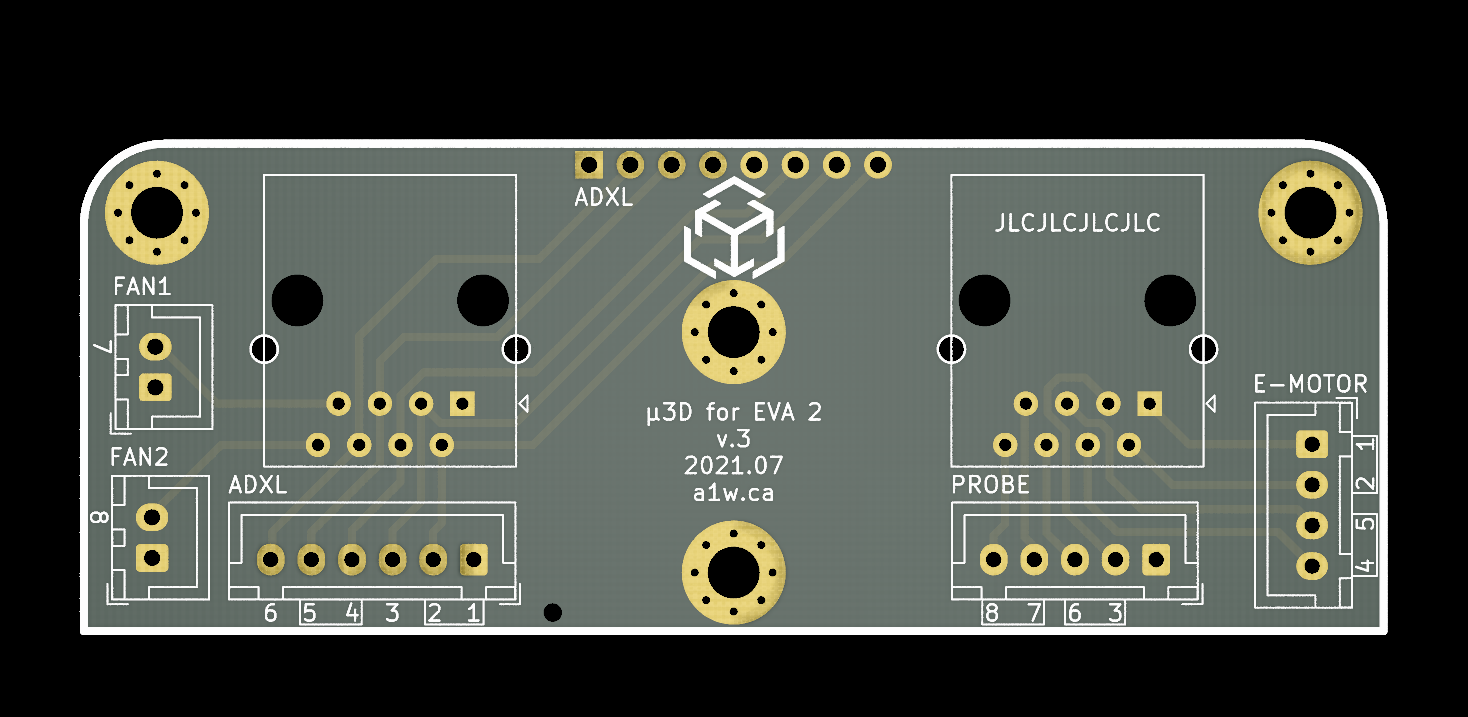
In v.3 I replaced those mounting holes with 8-pin 2.54mm header holes at the top of the PCB.
This would make it possible to either:
- solder the ADXL with 8-pin headers directly to the PCB, or
- solder an 8-pin socket and then simply slide the ADXL (with pin headers) into the socket
The pin assignments on the 8-pin headers is identical to the ADXL board, and would use the twisted pairs 1-2 for GND/SCL, 3-6 for SDA/VCC, 4-5 for SDO/CS. The INT1 and INT2 would remain unconnected in this case.
Personally I don't really like v.3 because it's not flexible and forces you to use specific twisted pairs for the pins. In v.1 and v.2, you can choose which pairs to use and easily add your own decoupling capacitors if needed.
I guess I can leave it to the community for suggestions on which board is better.
Discussions
Become a Hackaday.io Member
Create an account to leave a comment. Already have an account? Log In.