 Jithin Sanal
Story
This Uploader eliminates the need to remove the Arduino board from the PCB or circuit board. A USB cable is not even required to upload the code. Simply wirelessly upload the code whenever you like using a laptop or a desktop.

OTA Code Upload or Over the Air Code Upload is what this is called.
TLDR Here is a Complete Video Tutorial
Details for Bluetooth Module HC05
Bluetooth module HC-05 is used in this project. In addition to being inexpensive, it is also one of the most commonly used modules in many other projects. You should be able to obtain one from Amazon or eBay.com with little difficulty.
A wireless code uploader for Arduino: How did I make it?
This project will be divided into two stages.
- The Bluetooth module must be configured as the first step in the process.
- Wireless code upload is the second step.
The circuit of the first and second parts differs by a small amount. If you use the PCB I designed, you can easily change the connection using jumpers on the PCB itself. Using jumper cables is an easy way to set this up if you are using breadboards.
Making the Wireless Programmer Shield – Behind the Scenes
Circuit Design
I have designed a circuit that will allow us to connect the Arduino and Bluetooth module and do the configuration and wireless code upload without having to disconnect the Arduino and Bluetooth module.

For circuit design and PCB layout, I used Altium Designer. You can design and create your own PCBs for your project, as well as complex and multi-layer PCBs for industrial use, with this powerful tool. In the description, I’ll include a link to the free version. Check it out!
Actually, this PCB will serve as a shield for the nano-based Arduino. The Bluetooth module can be attached to the shield. Almost all of the digital and analog pins have headers, so you can use this board for your projects as is.
All you have to do to switch it from configuration mode to wireless programming mode is move the Jumper.Battery, adapter or USB data cable, and power bank are all options for powering this board.

Then, using Altium, I designed a compact PCB on which I could neatly mount all of the components. Here, you can see that the board has routing on both sides, which means it’s a dual-layer PCB. All that’s left to do is export the Gerber file to your computer.
Setting up the PCB
PCBWay provided me with a PCB that I ordered. In addition to PCB prototyping, PCBWay specializes in PCB assembly and neat and tidy PCB assembly.
The PCBWay website has an instant order form that you can use to place an order. On the next page, you’ll be taken to a form where you can provide more detailed information about the board. The PCB specification screen allows you to update your board’s information. You should be able to upload your Gerber file and submit it for review on the next screen. As soon as the review is complete, you can add the PCBs to your shopping cart, pay for them and wait for them to arrive.
Soldering the components and the PCB together is the next step. Verify the polarity of the components before soldering them on the board.
Step 1 – Upload Baud Rate
In this case, the HC05 module is supposed to upload a code to Arduino when it receives a code from our laptop. For this, we must ensure that both the Arduino board and the Bluetooth module have the same baud rate. Each board has its own baud rate at which programmes are uploaded. Arduino Nano with Atmega328 operates at 57600 baud, while the Arduino Nano with Atmega168 operates at 19200 baud.
We send AT commands to the Bluetooth module in order to configure it. There are a number of ways to accomplish this. I decided to configure the Bluetooth module with an Arduino.
Step 2 – The Circuit
This is the circuit for configuration.

- HC05 GND to Arduino GND Pin
- HC05 5V to Arduino 5V
- HC05 TX to Arduino Digital Pin 10 (soft RX)
- HC05 RX to Arduino Digital Pin11 (soft TX)
If you are using this...
Read more »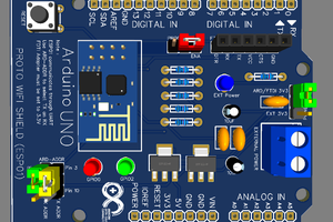
 Mrinnovative
 Lithium ION
 Sagar 001
 ElectroBoy