 Subir Bhaduri
So its all about the optical mouse's superb built-in camera and the way it detects movements. You can see some detailed explanation in this article here. The built in camera takes about 3k+ images per second of a small region directly beneath the mouse. And then it subtracts each image from the previous to identify if the image has shifted due to a shift in the mouse's position. This shift is detected and that is what is reported to a computer.
If you have used a camera, how difficult is it to keep it steady when the object is too far? Similarly how difficult it is to keep steady if its a macro shot of small objects, right? When one goes towards higher and higher magnifications in a microscopy setup, you can see that its harder and harder to keep the image still, because of 2 reasons, A) Seismic vibrations are everywhere and B) The magnification also magnifies the vibrations on the formed image by the same amount. So a 1000x microscope will magnify a feeble ground vibration 1000 times in a formed image (interesting article here on this subject). Just the touch of your hand on the device can disturb the image. So while microscopes are rigidly constructed to prevent vibrations from causing a shift between the object and the imaging system, and labs invest tons of money to keep their microscopy apparatus on vibration free platforms, we on the contrary want to make a 'flimsy' microscopy platform which is very susceptible to vibrations. The image sensor is our optical mouse which tries to find if the image has moved and by how much, while the remaining part of the 'flimsy' microscope amplifies any vibrations on a non-rigidly coupled object plane.
A (long) video explanation of this trick (our innovative contribution to frugal seismography) can be found here:
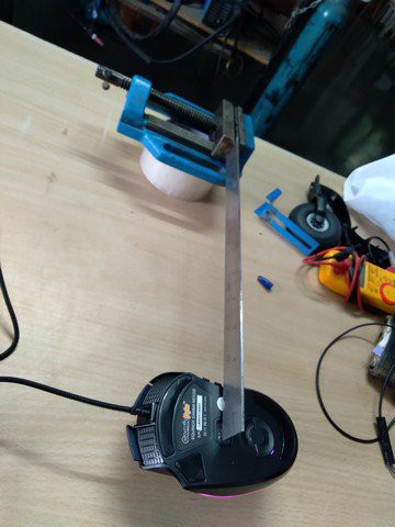
We made many models and experiments before settling in on a design where the ease of making was an essential feature. This conscious decision is driven by the idea of frugal science where the components as well as the methods and skills needed to make something are carefully oriented towards simplicity. The first successful prototype we had built is explained in the video below.
In the first proto, the magnification was small and the construction was complicated. The lens used was from a 'Foldscope' microscope, the 1$ microscope developed and promoted by Stanford University's Manu Prakash. The design of the seismometer was of the Lehman type, or 'garden gate' type.
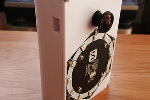
The second prototype modifies many aspects of the first, prominent being simplifying the construction of the system as well as lengthening the system to increase the magnification. Additionally, I removed the lens of the mouse itself and placed it as far as possible (limited by the illumination of the laser on the image chip). The focal length of that lens is about 1 mm or so. So keeping any brightly illuminated piece of plastic (with some surface features) right in front of the mouse lens at 1mm distance, will form an amazingly large image on the mouse sensor. If this plastic piece moves due to vibrations, then the image on the mouse moves.
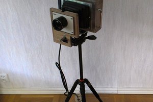
Second prototype :
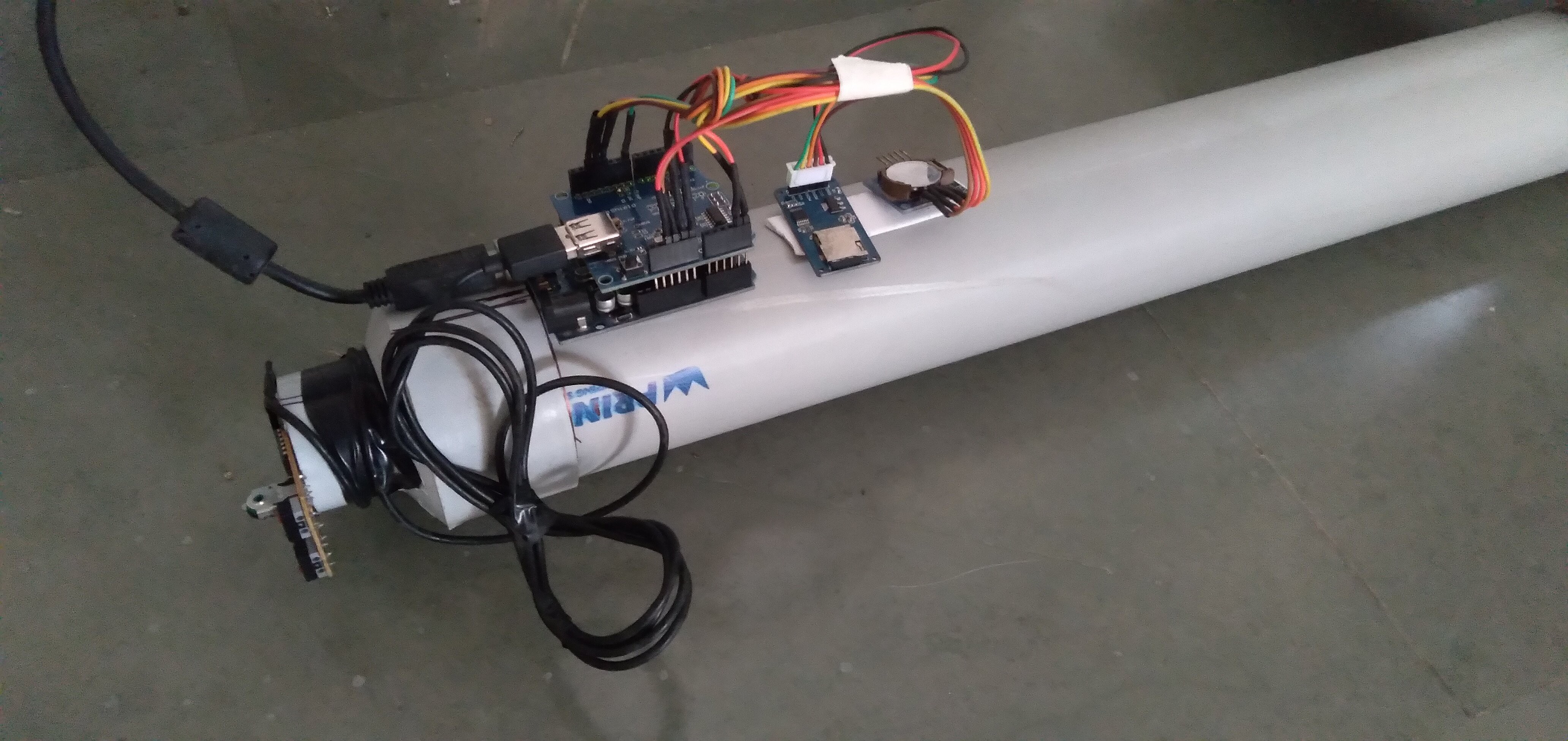
In the above prototypes, the mouse connected directly to a computer. However for long term recording we need something which is not dependent on another costly computer. Hence, in this version the mouse was connected to an Arduino Uno and its USB shield, a SD card module to store the data, and an RTC module to know the precise UTC time during recording. The whole device is powered by a 5V wall plug connected to the Arduino's main power input jack. The data read can be stored on an SD card and analyzed later.
The code to run on the Arduino can be availed here. It is still a work in progress and many issues need to be addressed.
Next?
While this project works, there is much stuff to do.
- Try to update the device with a high DPI gaming mouse (see project logs for info).
- Record lots of data and see if this device is actually...


 AIRPOCKET
 Dan Schneider
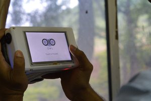
 jimmy.c.alzen
Oh, by all means use the mouse image comparison system - I was thinking more in terms of not needing the whole mouse, and using a consistent chip that you can order in bulk.
Some of the high-end gaming mice use chips that have insane resolution and speed - 9k dots per inch or so, and have updates of 1000 samples per second.
As an example, I have a library online that will interface to the ADNS9800 chips, which has a frame rate of 12000 frames/sec and has a built-in laser, and another driver that interfaces to the ADNS2600 series.
That chip's a little pricey, but the driver can be trivially tweaked to interface to just about any other mouse chip.
The mouse sensors with builtin lasers are what quadcopters use for position sensing, and you can get these separately. I found one on eBay got $10US that includes the laser and focusing optics. The lens focuses the laser at infinity, so if you were to use this part you wouldn't need your own laser. Just point the lens at the vibrating film.
https://www.ebay.com/itm/401076976913?hash=item5d620cfd11:g:LYcAAOSwg3Nal6mE
I *believe* that chip has built-in motion sensing as a pin output, so you could put the arduino to sleep and have it wake up when motion is detected.
At any rate, your project looks really interesting and I just wanted to point out some options. I think the hard part will be the signal processing, but the hardware should be simpler.