 Open Green Energy
In the reference circuit diagram, the configuration is powerful enough to drive a white LED. But if you connect an RGB LED, instead of white you will notice that the RGB LED lights up however it doesn’t cycle through red green blue color.
The circuit is not working because the output from the circuit is not a steady DC output rather it is a high-frequency pulsating signal. In my breadboard prototype with only one LED, the configuration oscillates near 184.5KHz (see the image).
How to fix this Issue?
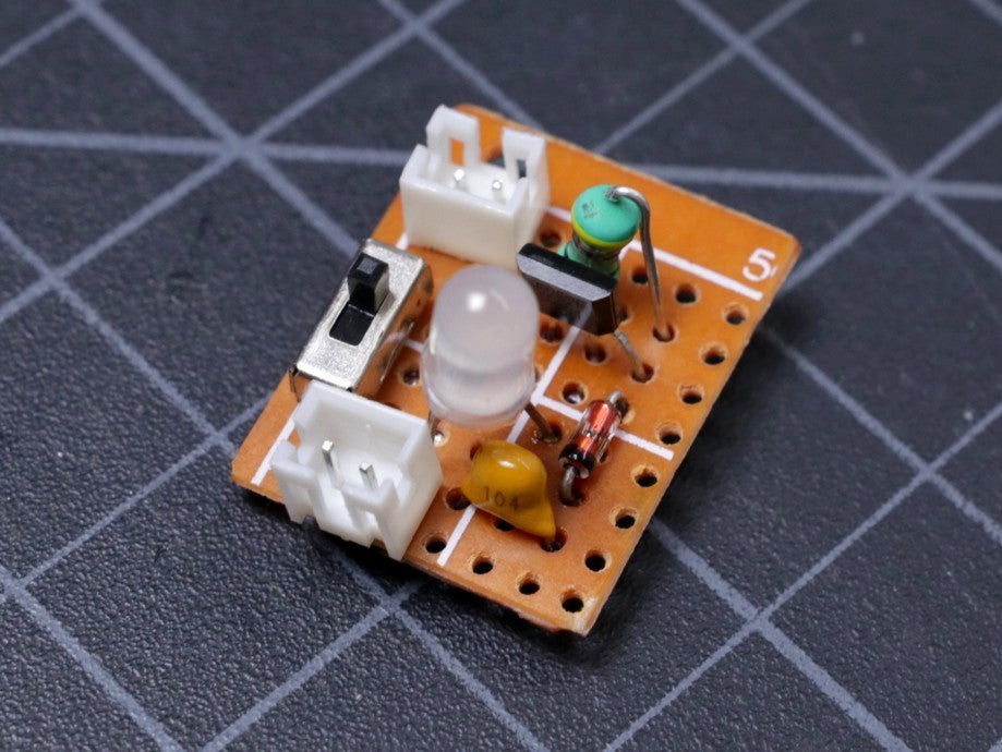
To fix this you need to add a buffer circuit at the output.
The buffer circuit is just a diode ( 1N4148 ) and a capacitor (10nF ) at the output before connecting the LED. The diode keeps the capacitor charged when the pulsating signal goes to 0 volts.
After adding the buffer circuit, you can notice that the RGB LED cycles through all 7 colors. Now you connect the oscilloscope at the LED terminal, the output is DC current with a little amount of ripple signal which is adequate for driving the RGB LED.
Discussions
Become a Hackaday.io Member
Create an account to leave a comment. Already have an account? Log In.