0%
0%
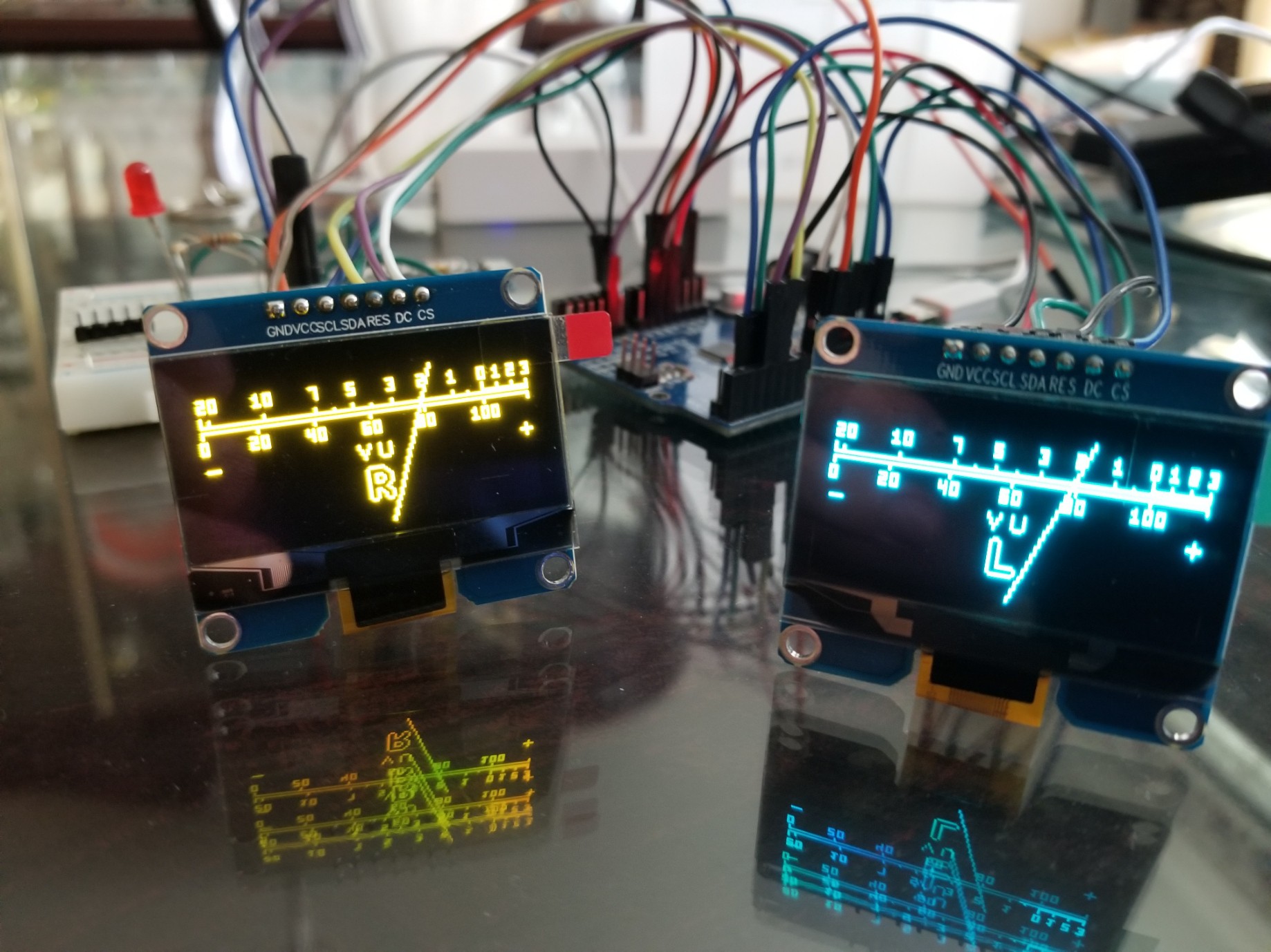
Digital VU Meter with Analog Physics
A digital VU meter that looks and moves like an analog needle with mass and spring oscillations
 sjm4306
Become a Hackaday.io member
Already have an account? Log in.
Just one more thing
To make the experience fit your profile, pick a username and tell us what interests you.
Pick an awesome username
hackaday.io/
Your profile's URL: hackaday.io/username. Max 25 alphanumeric characters.
Pick a few interests
Projects that share your interests
People that share your interests


 David H. Bronke
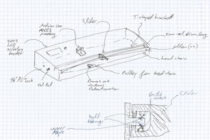
 uri.shani

 Bill Smith
Здраствуйте !!!! Проект полностью готов?