 shane.snipe
Top 3 struggles I have with robots and how this project solved them.
1) Cost too much. Mostly because of expensive servos and high end processors.
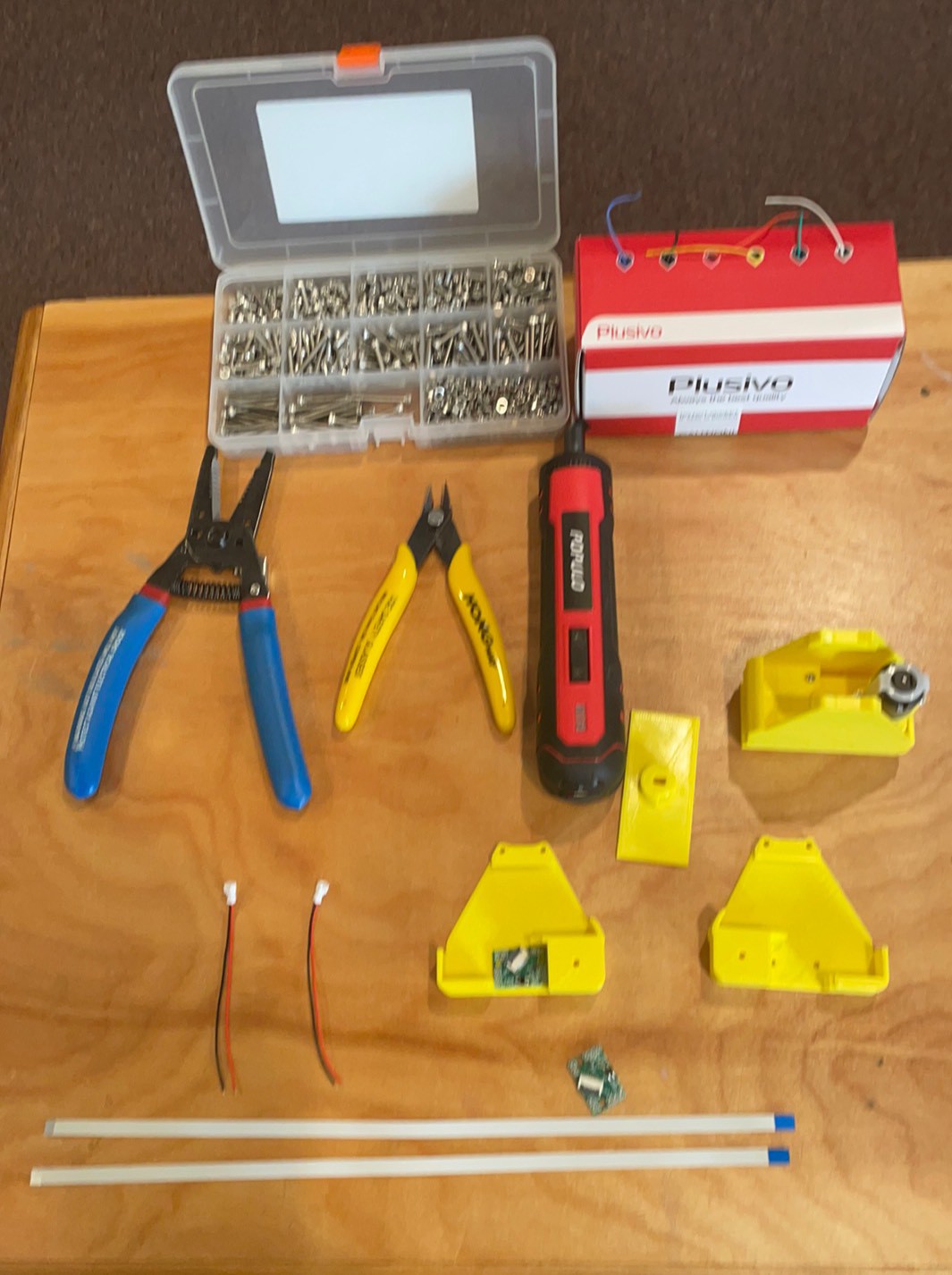
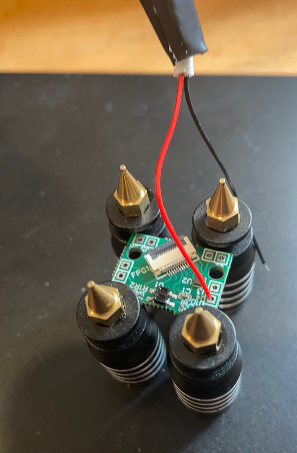
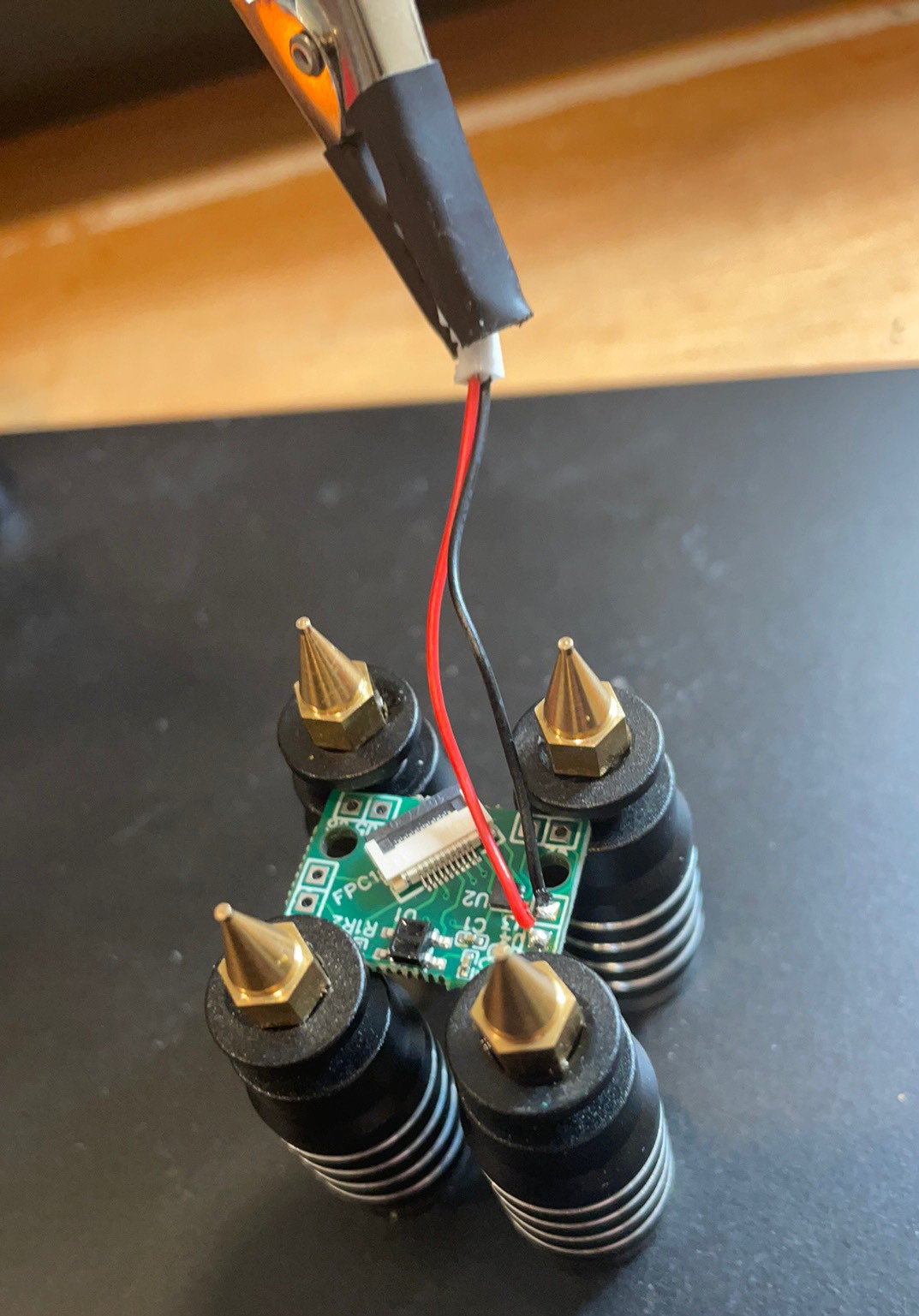
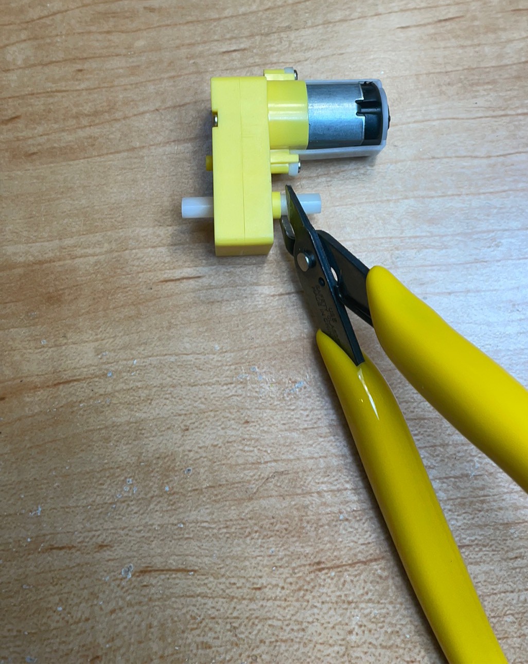
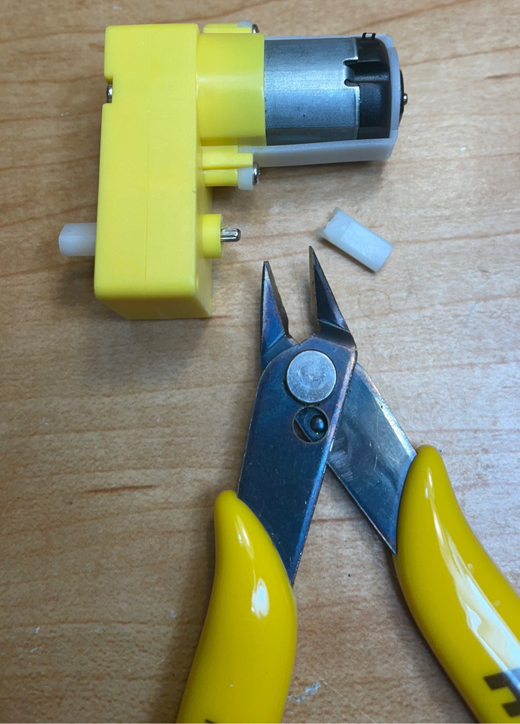
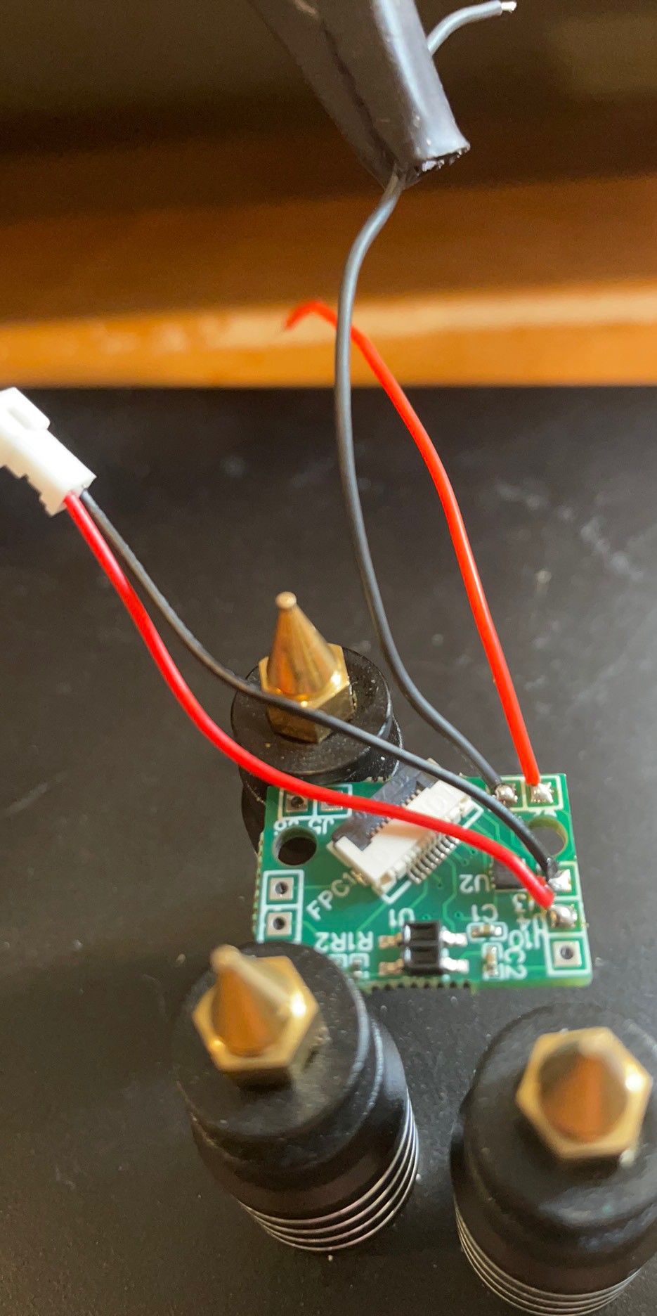
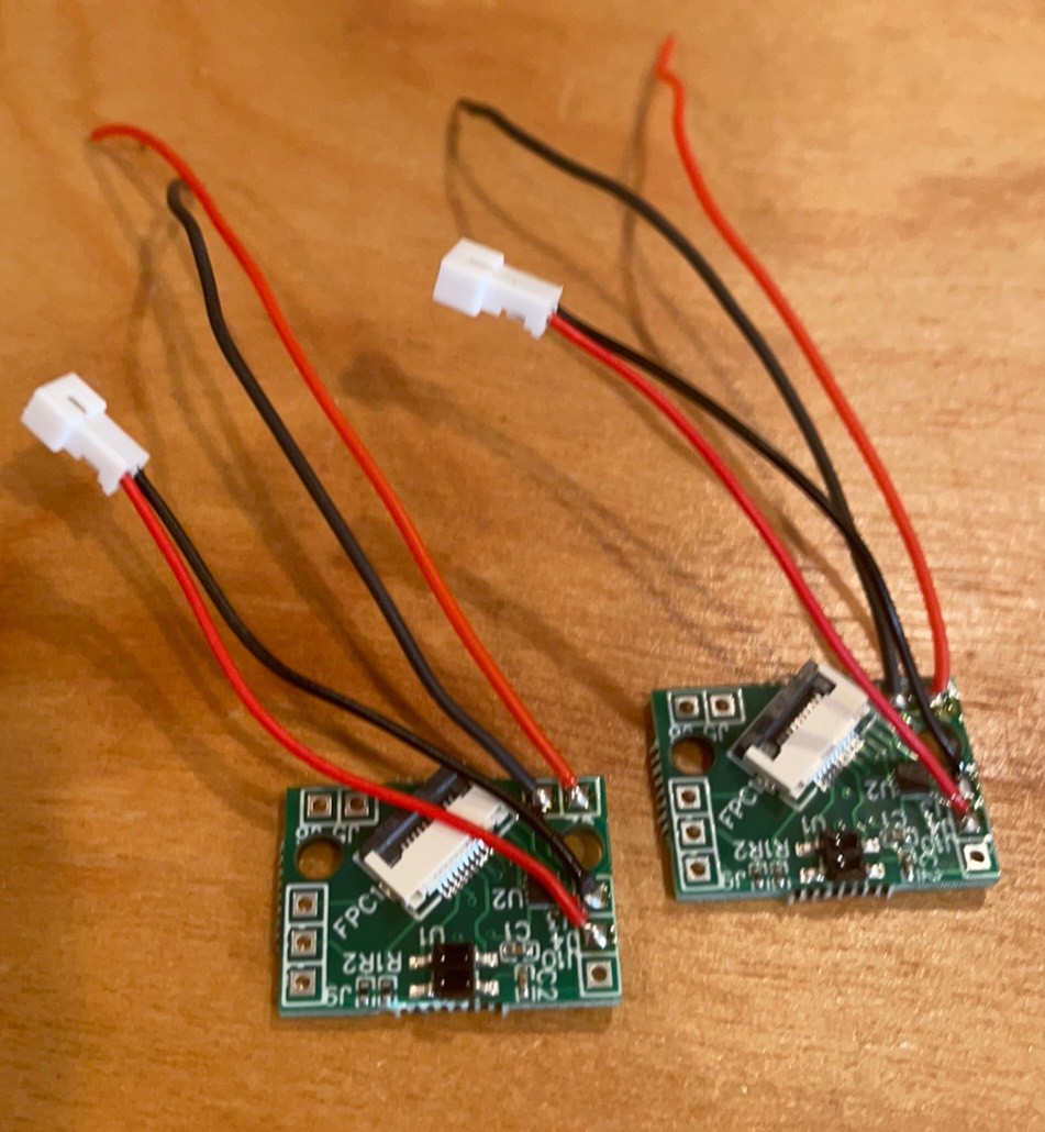
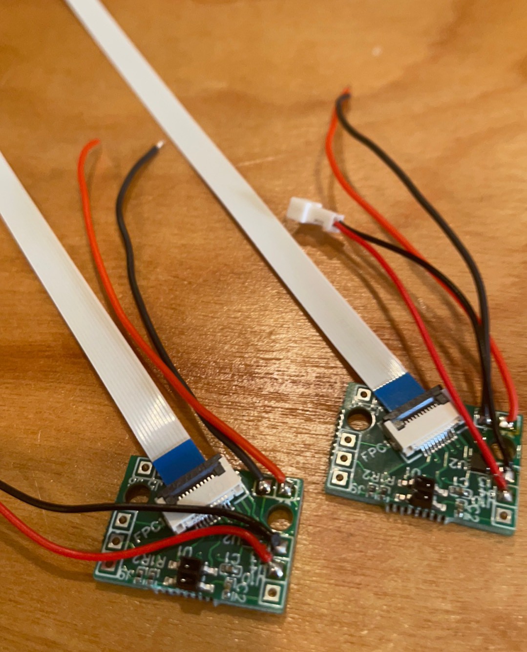
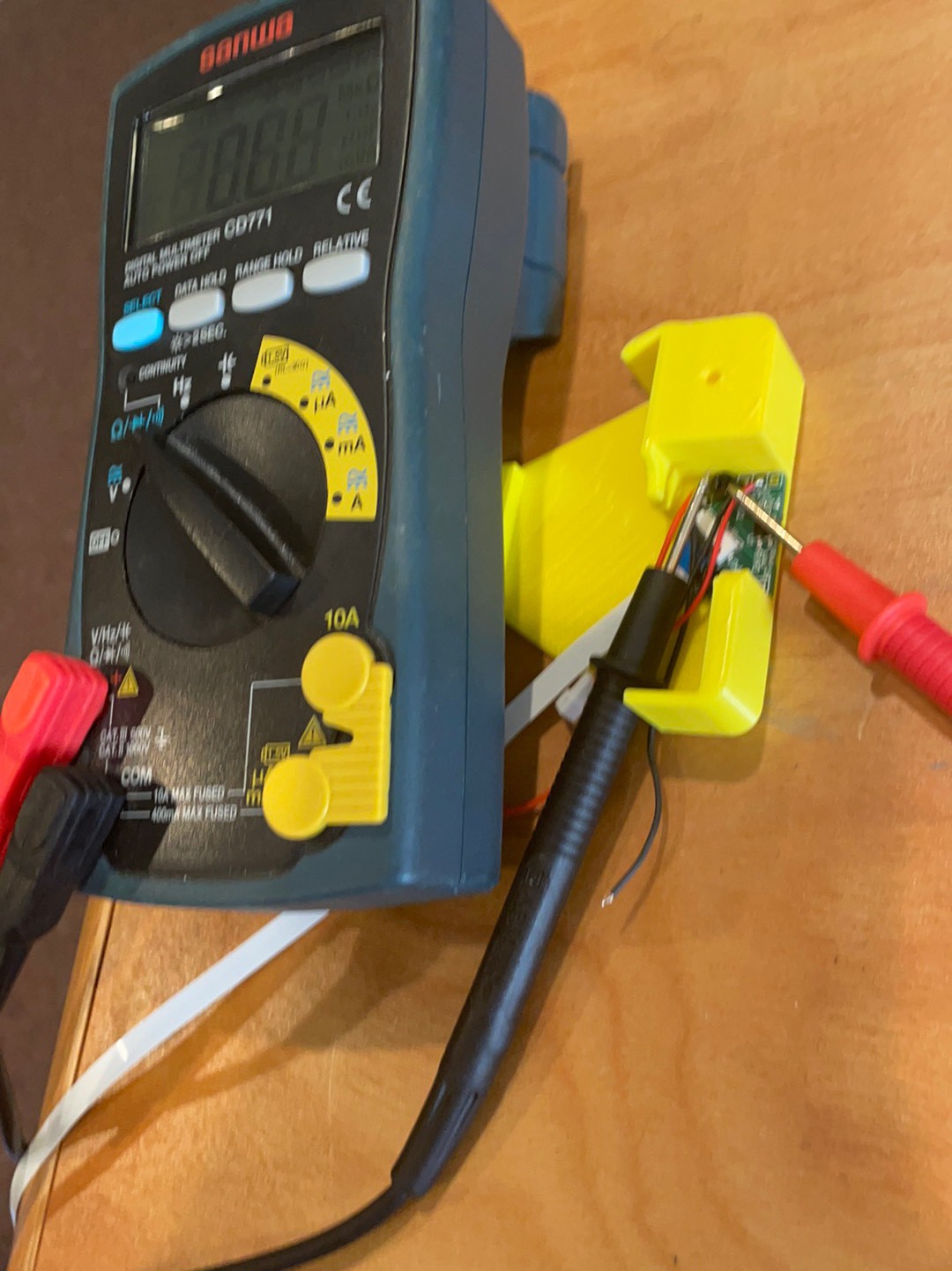
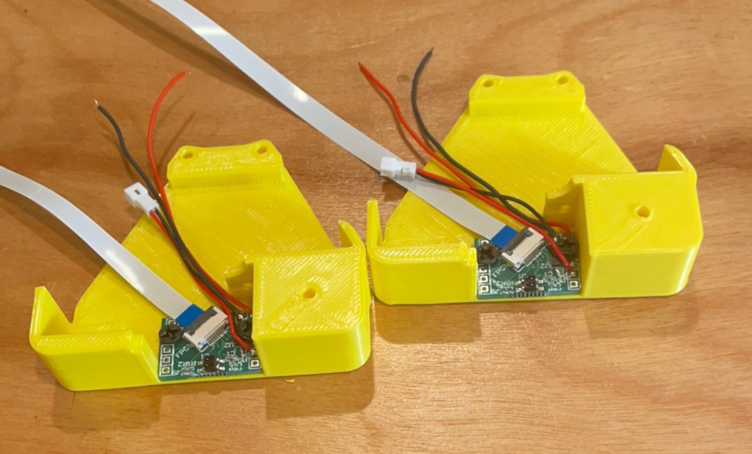
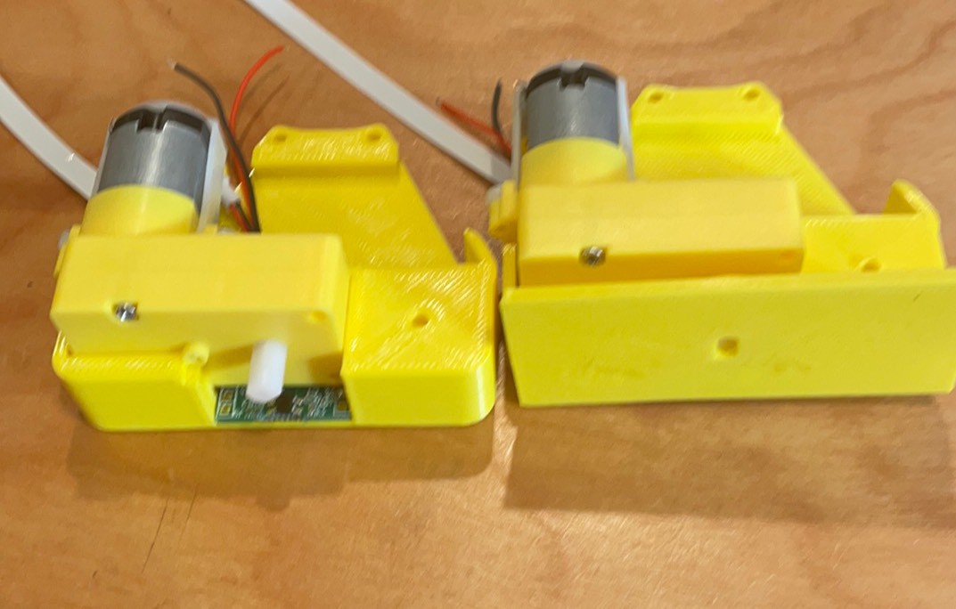
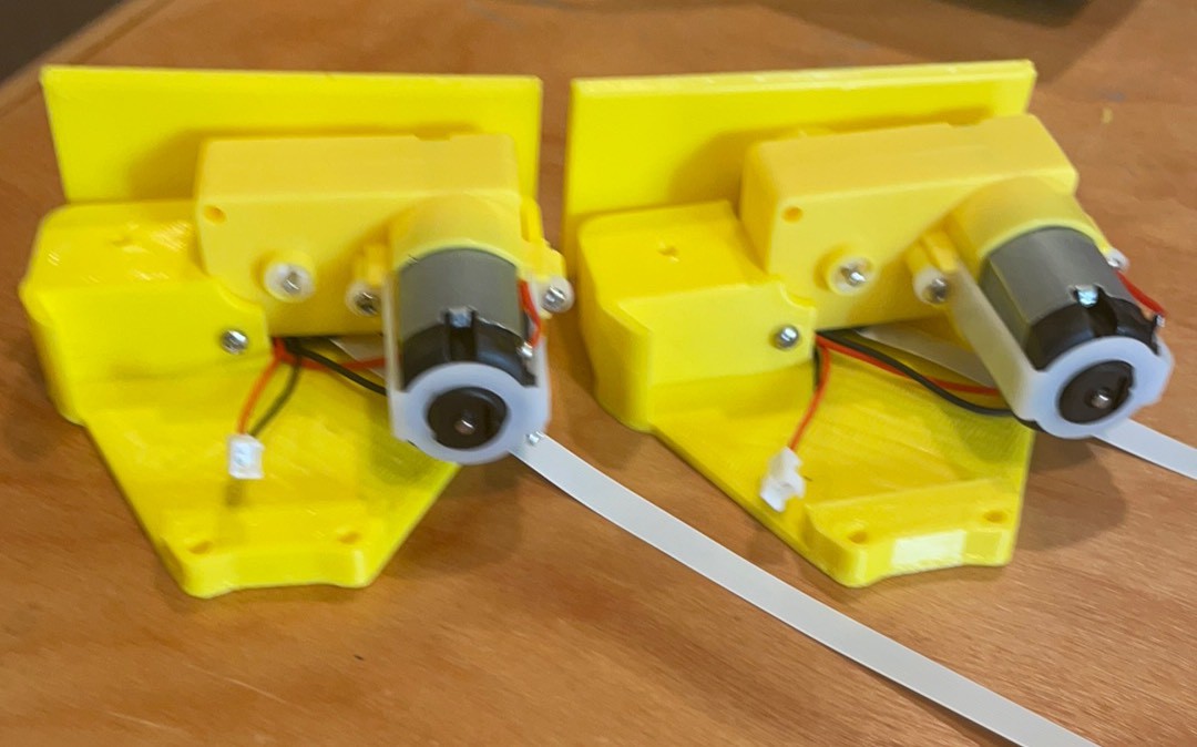
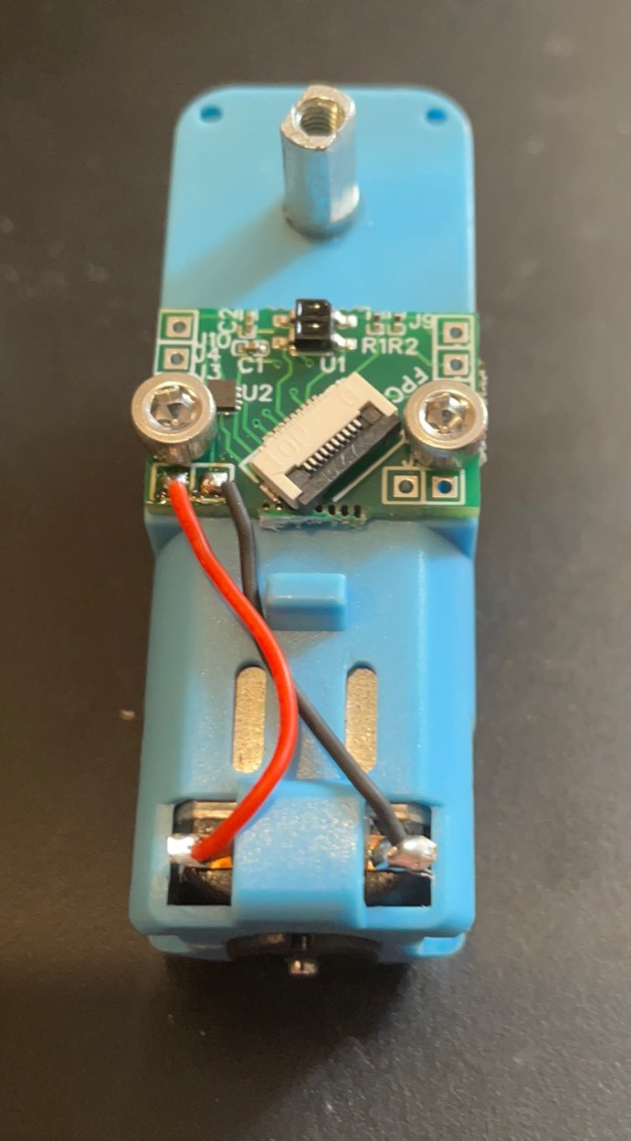
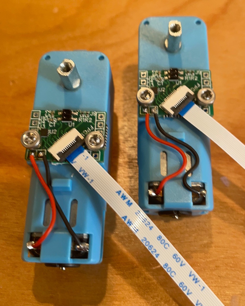
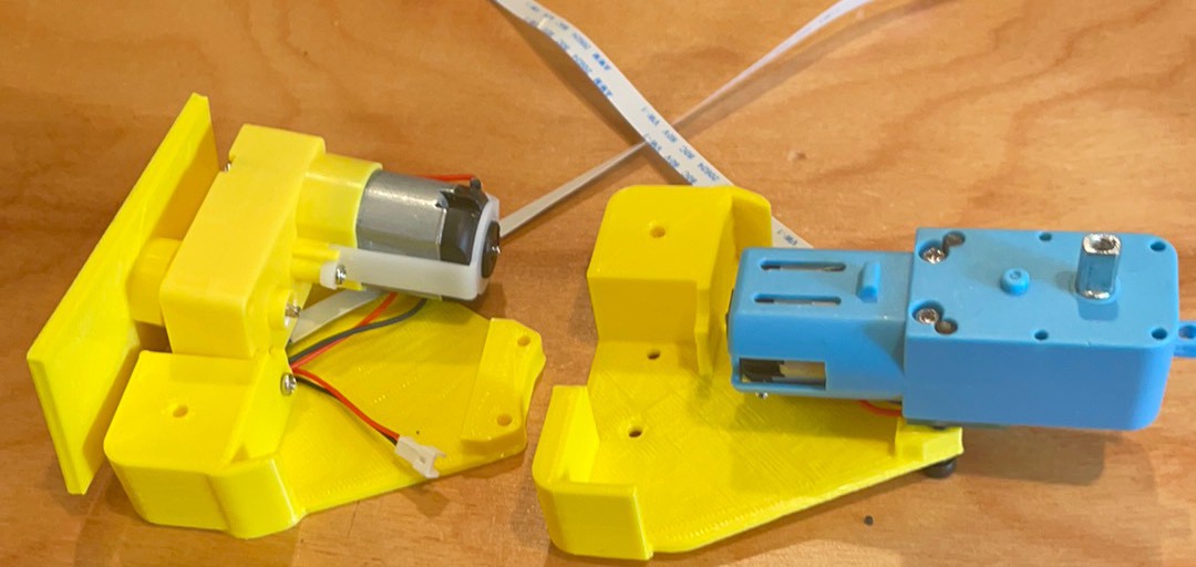
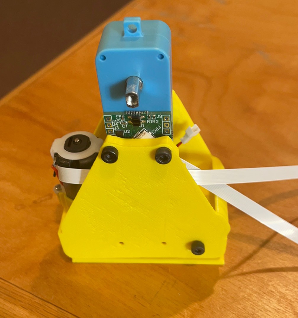
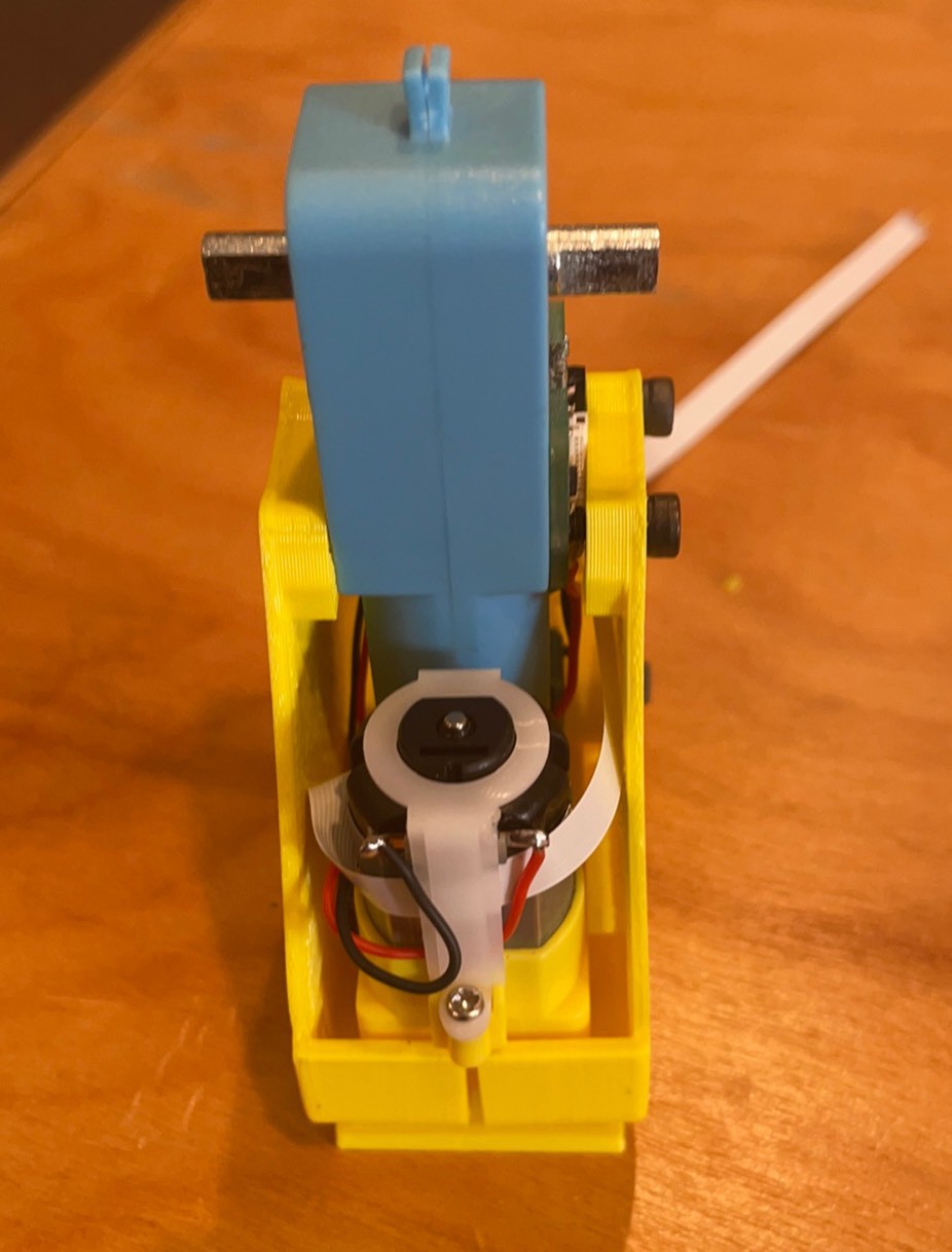
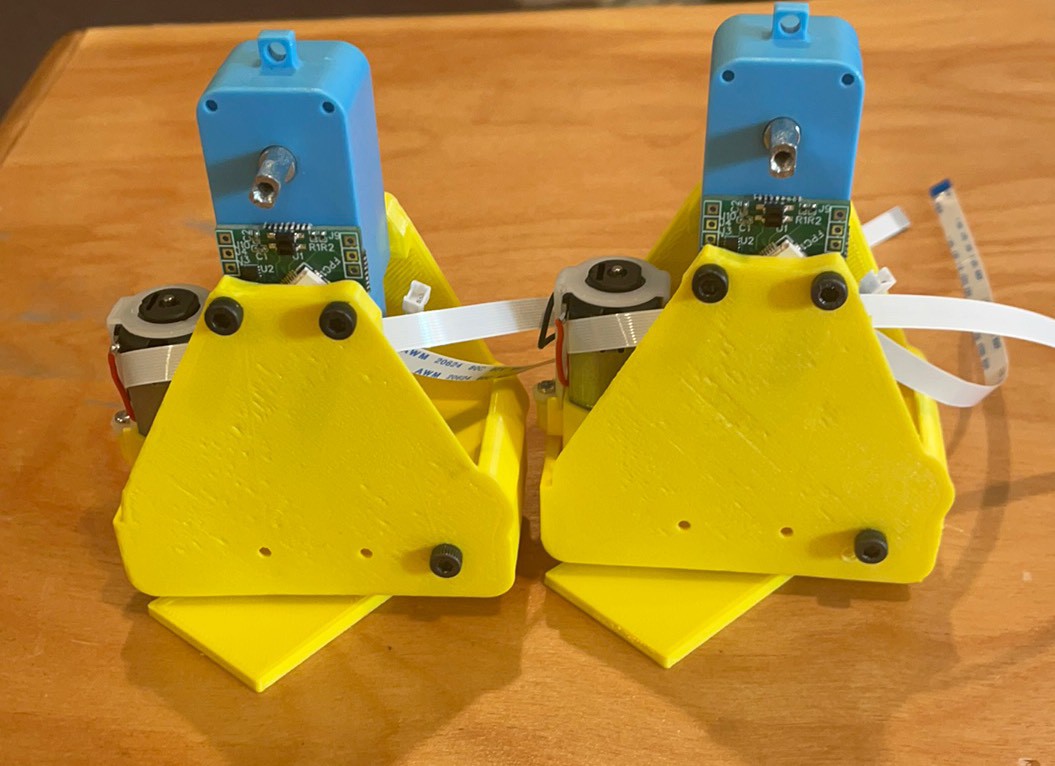
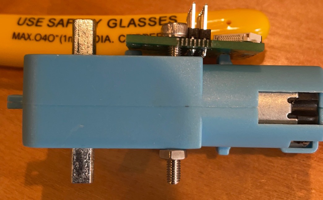
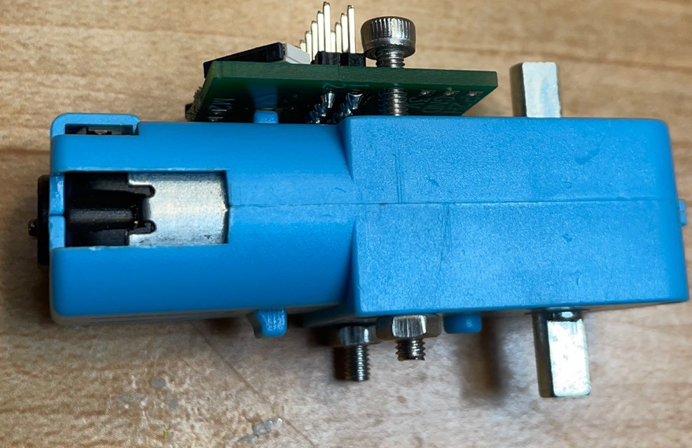
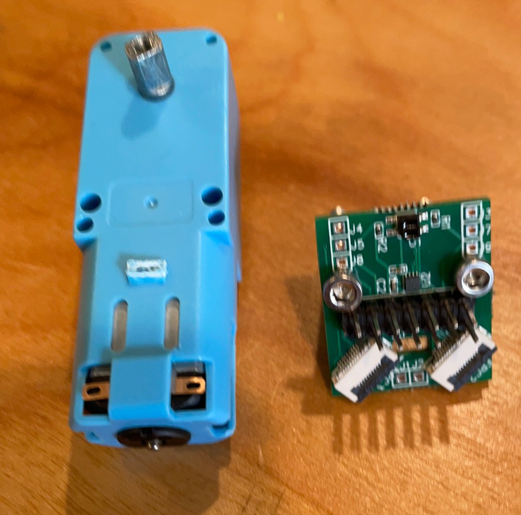
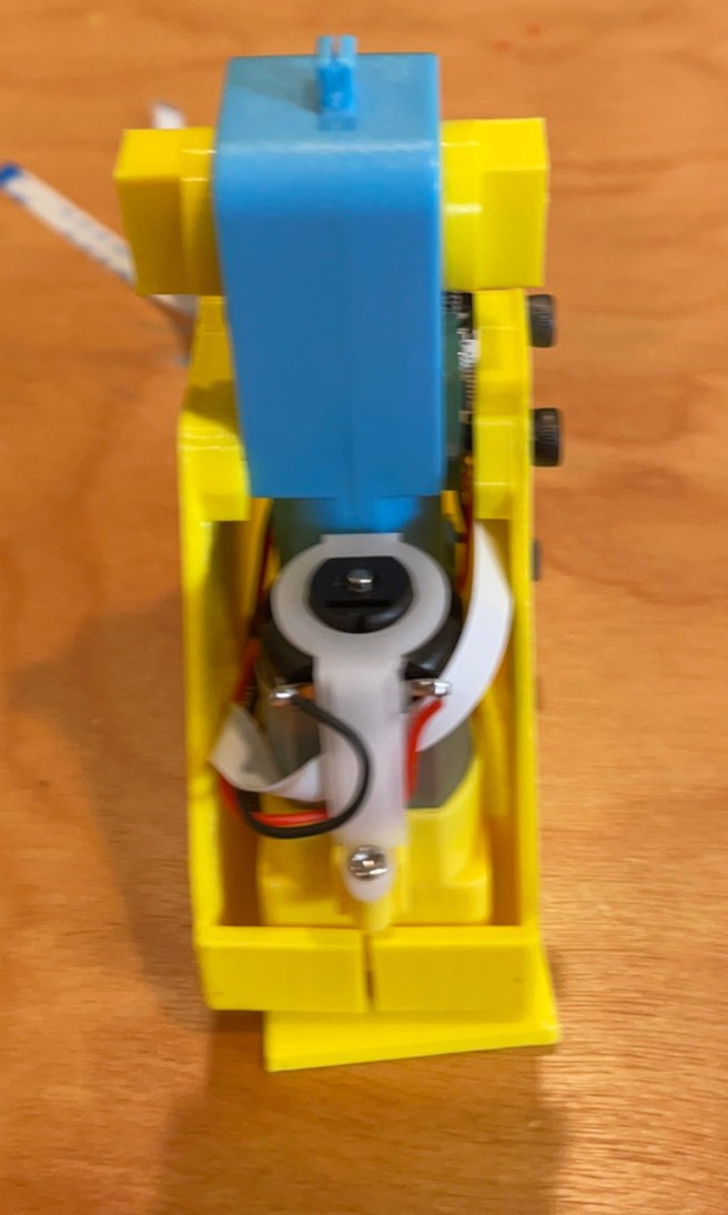
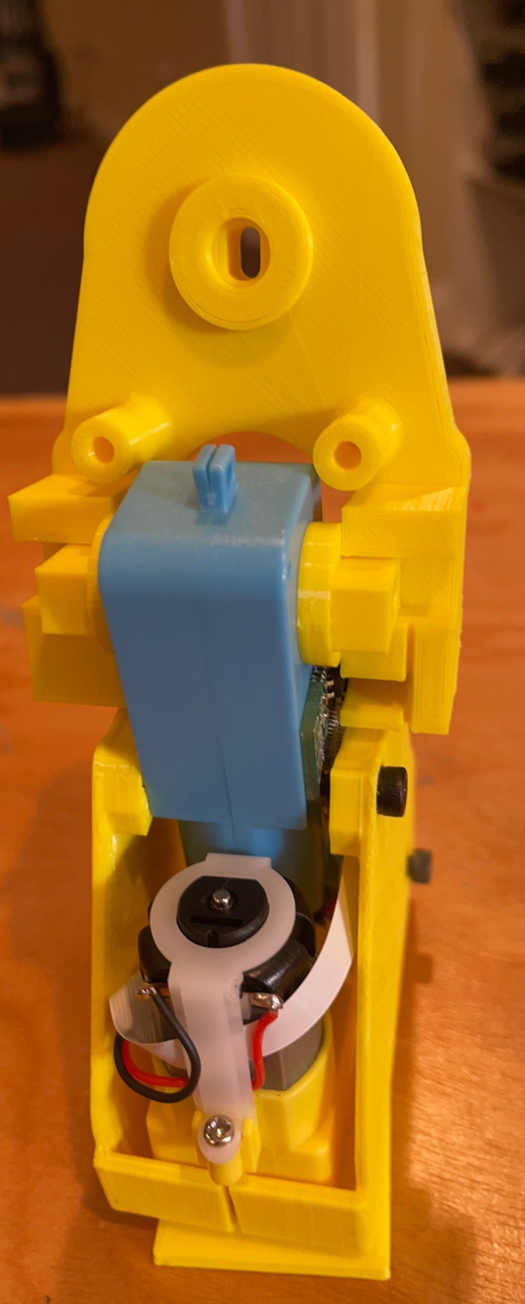
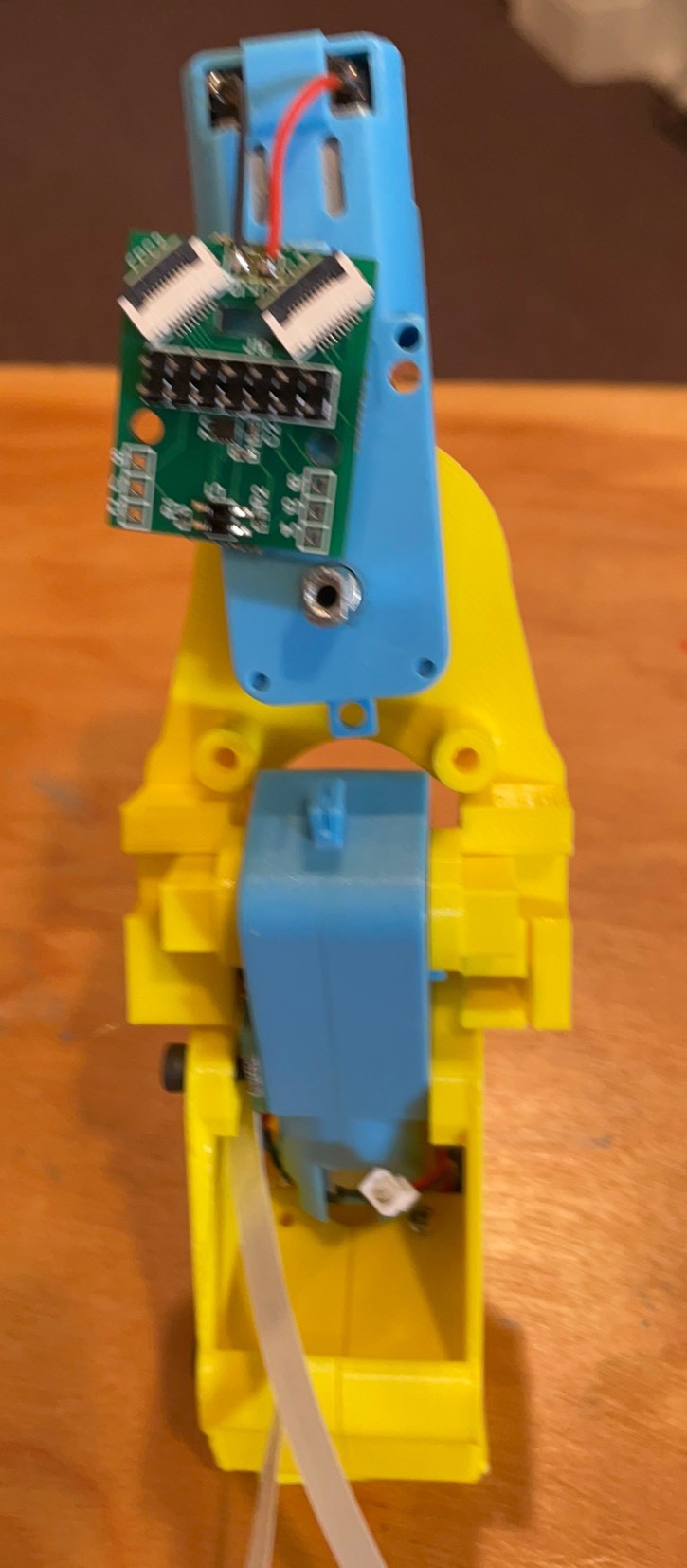
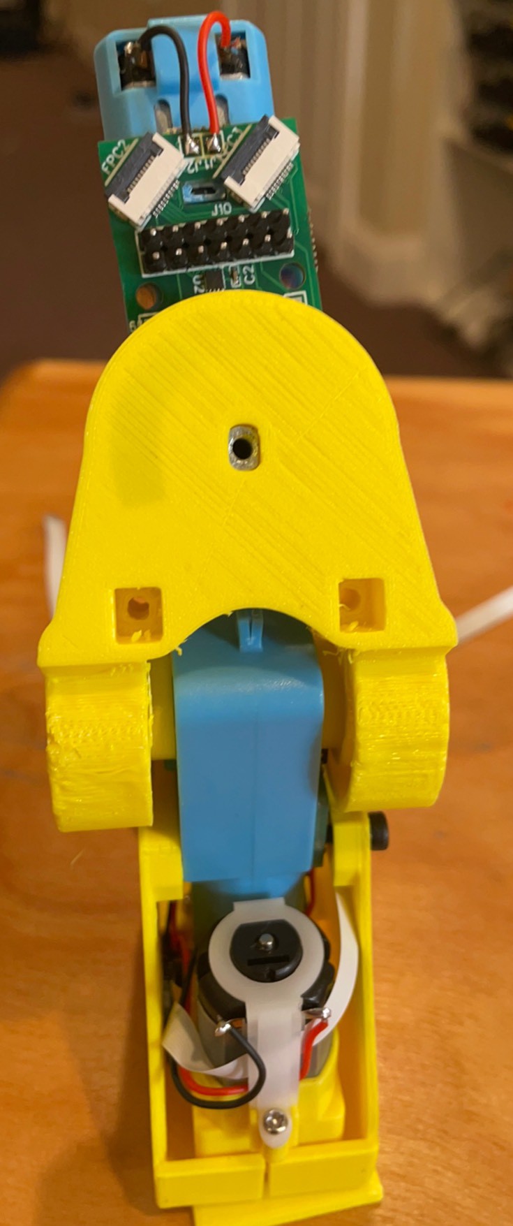
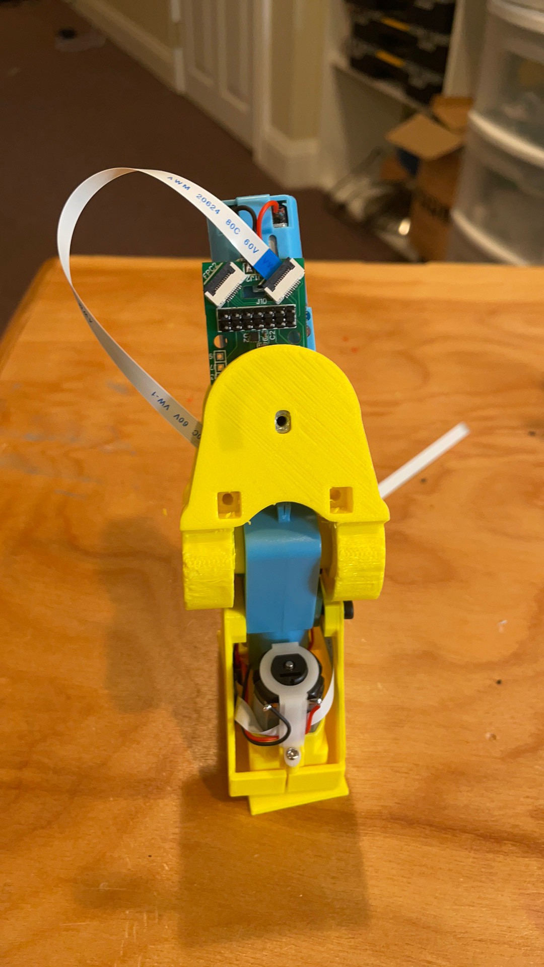
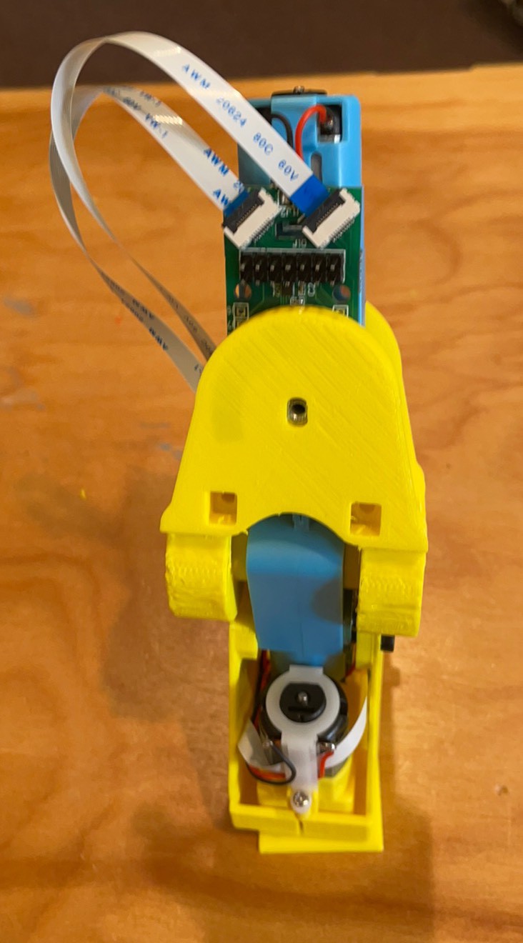
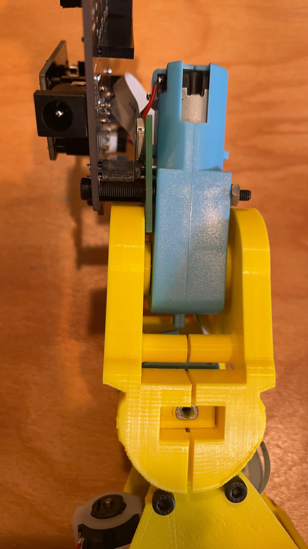
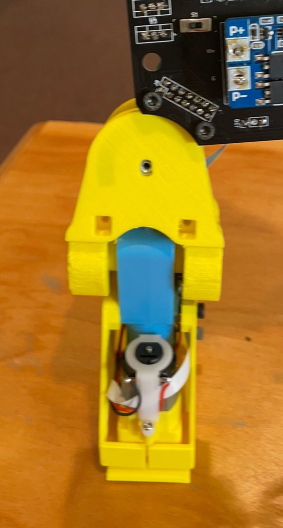
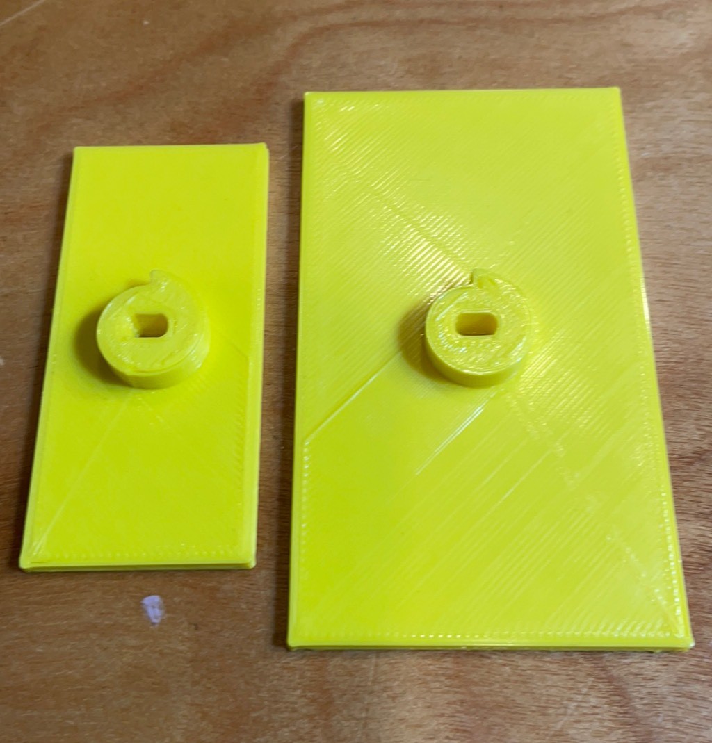
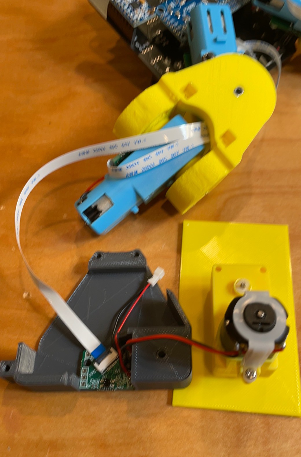
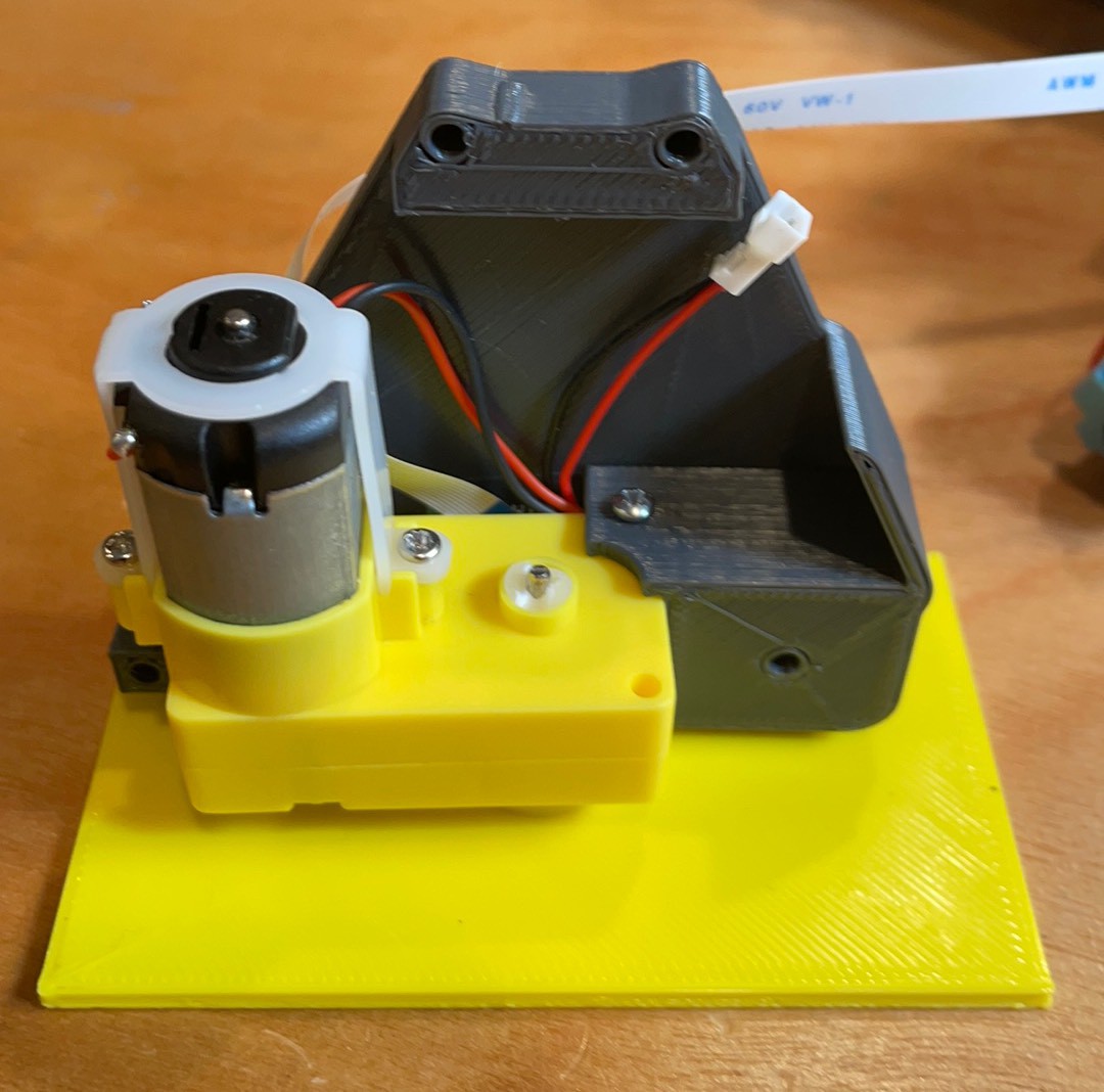
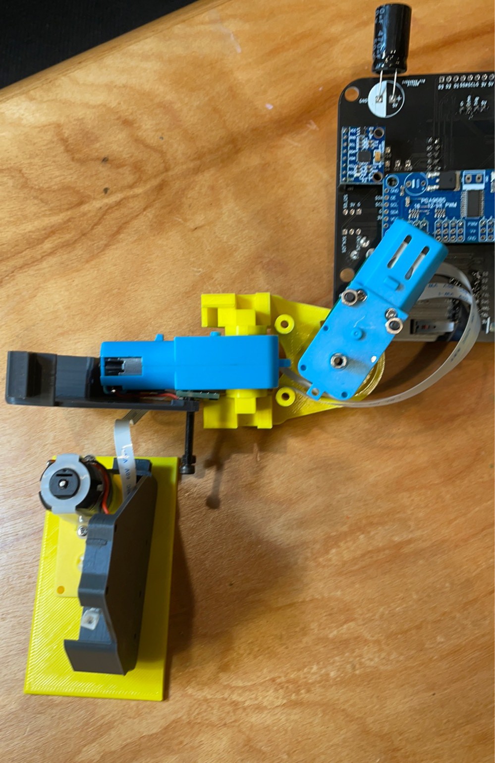
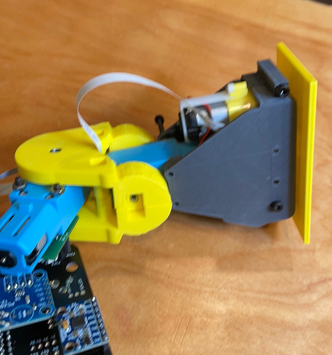
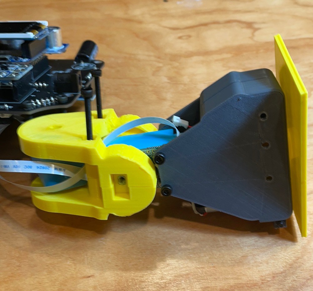
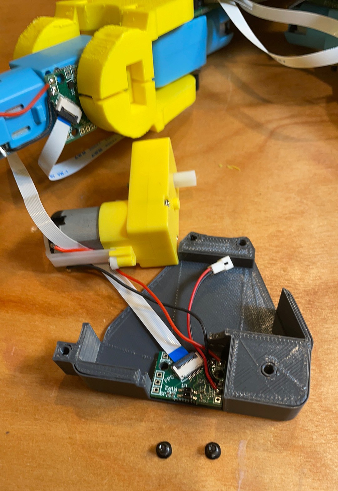
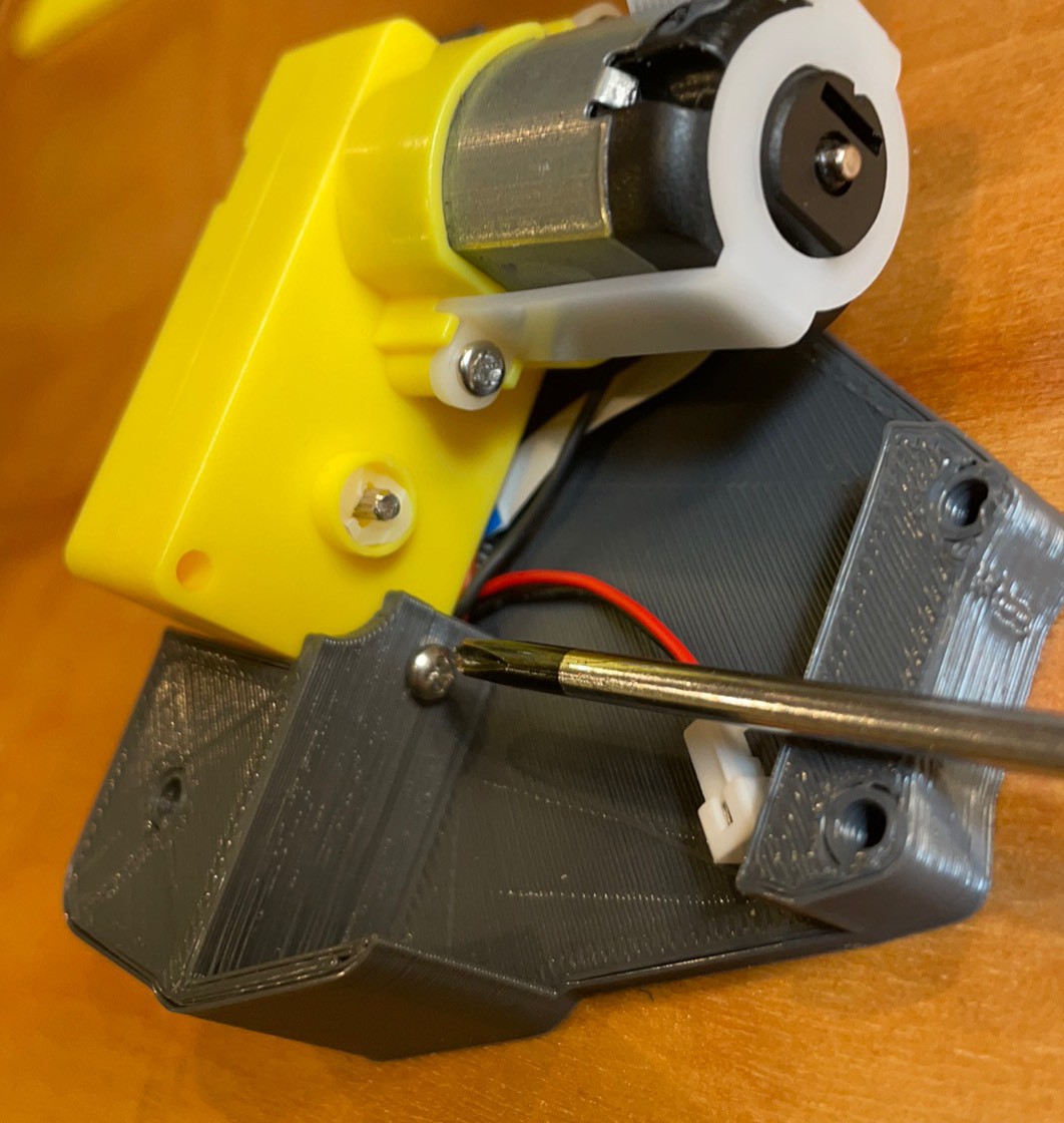
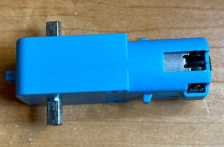
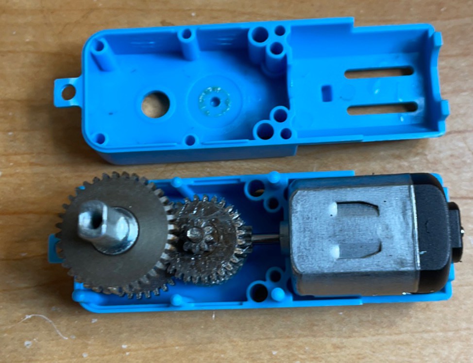
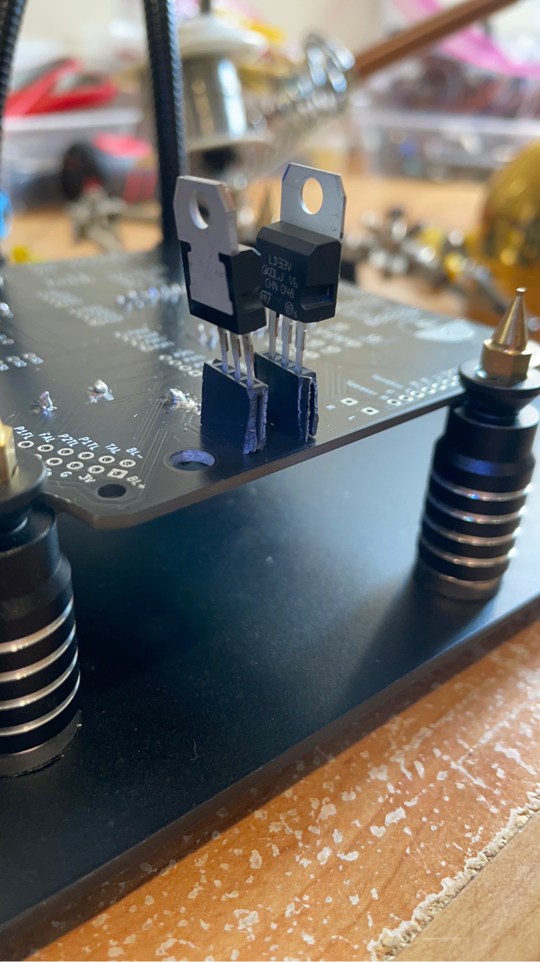
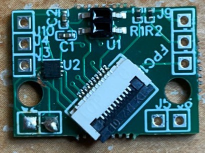
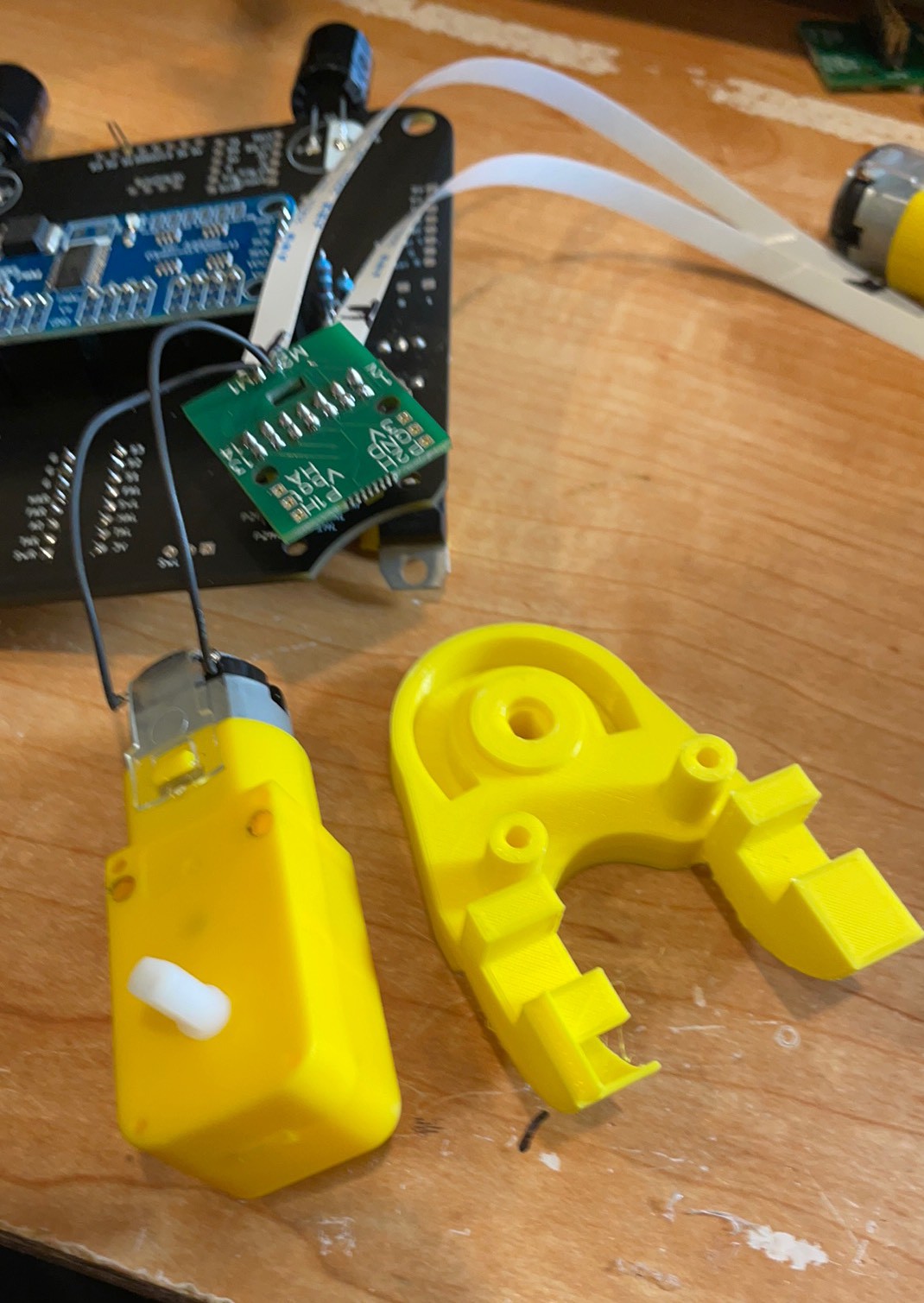
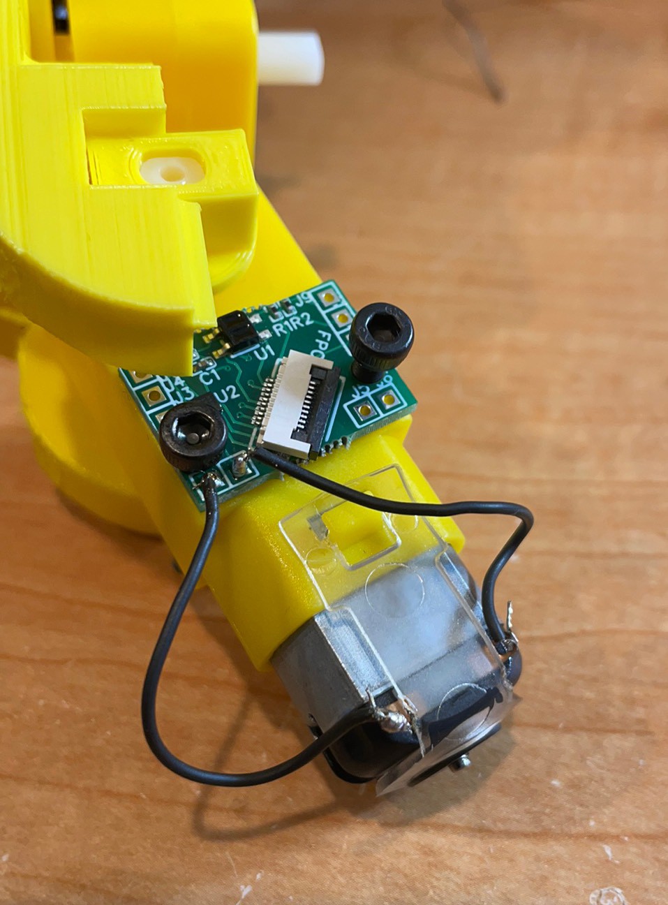
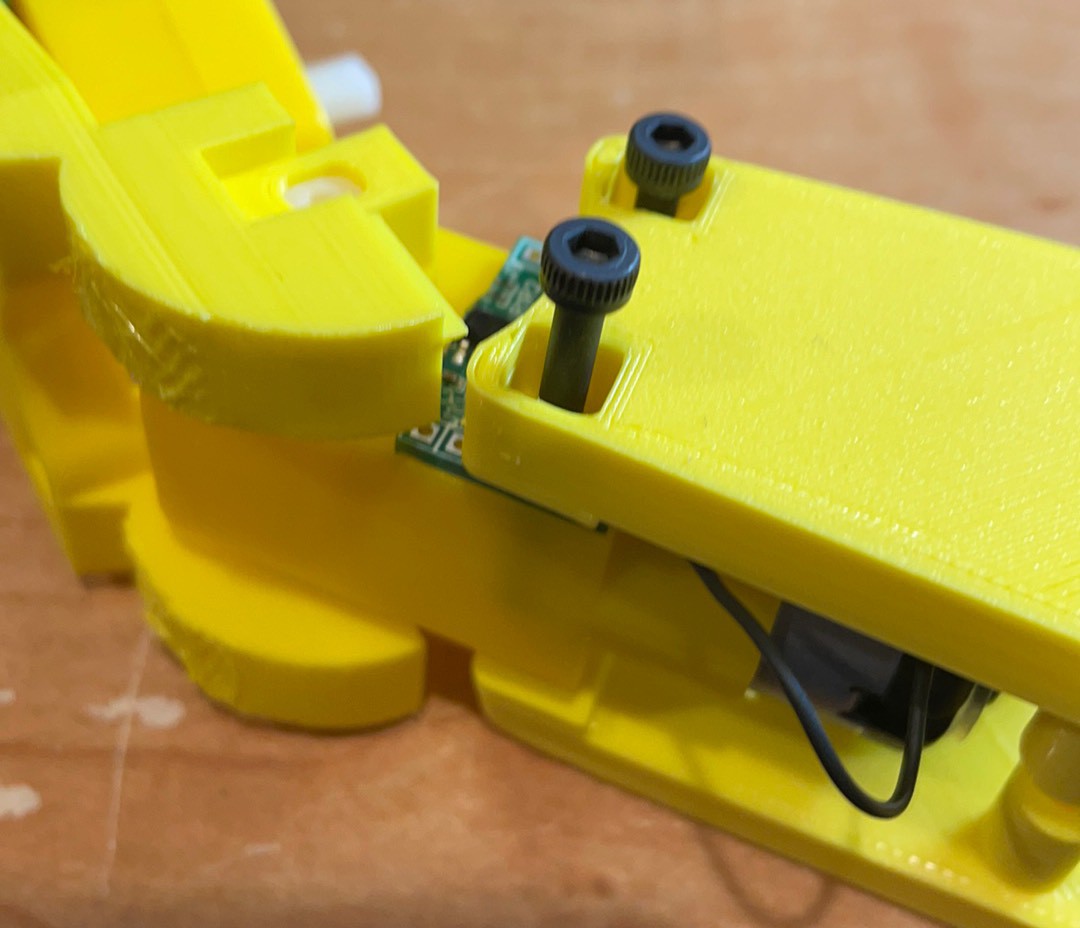
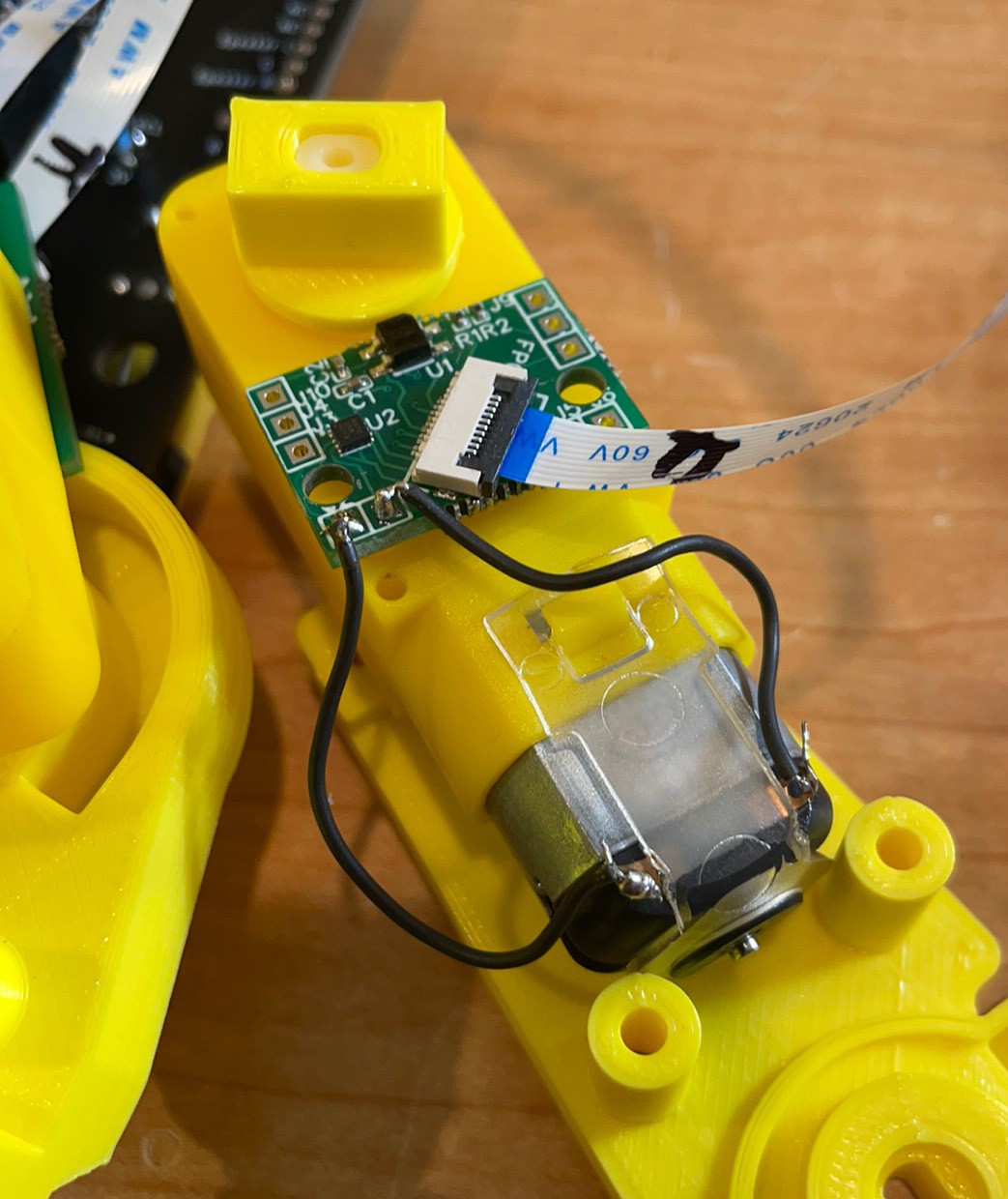
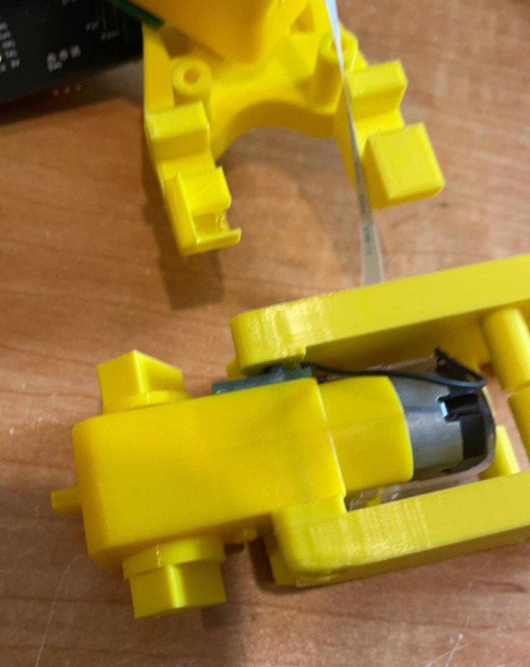
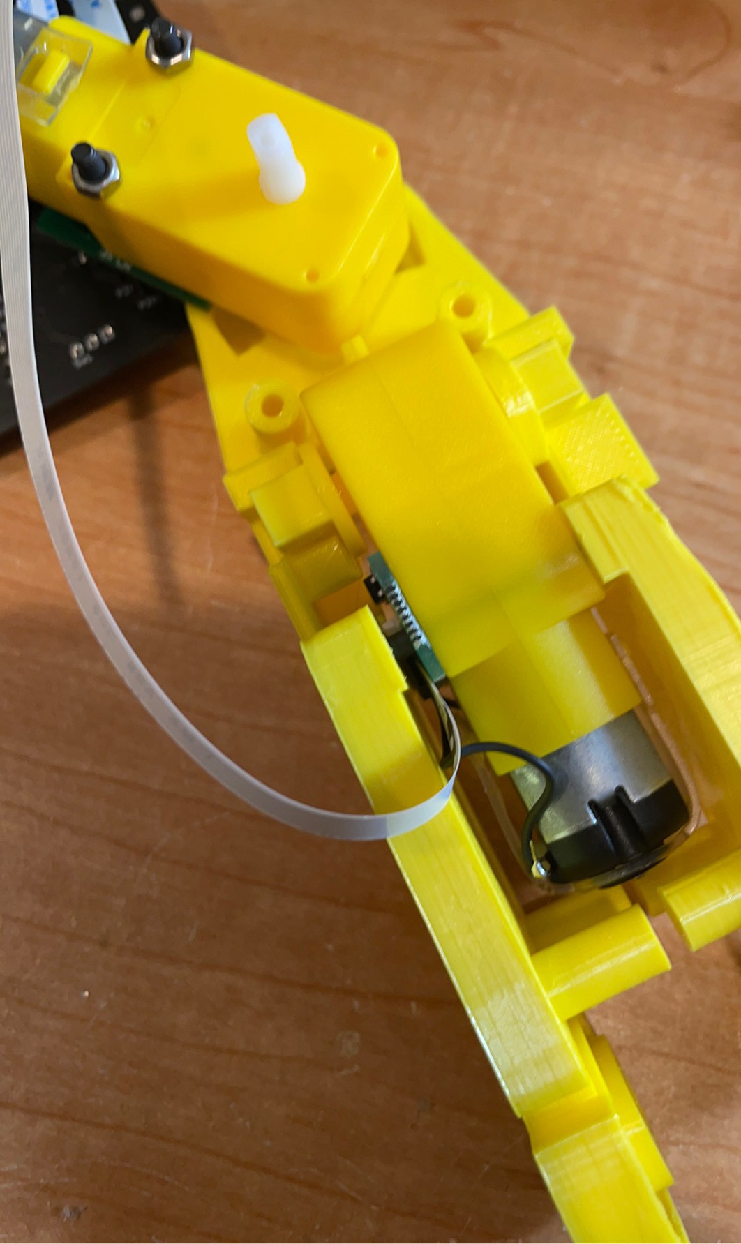
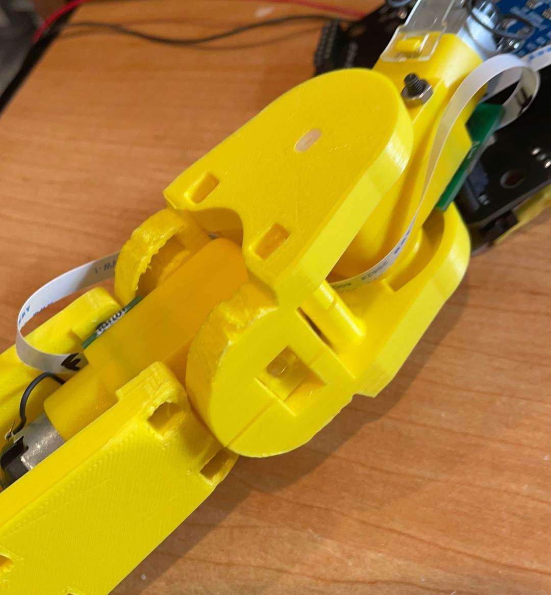
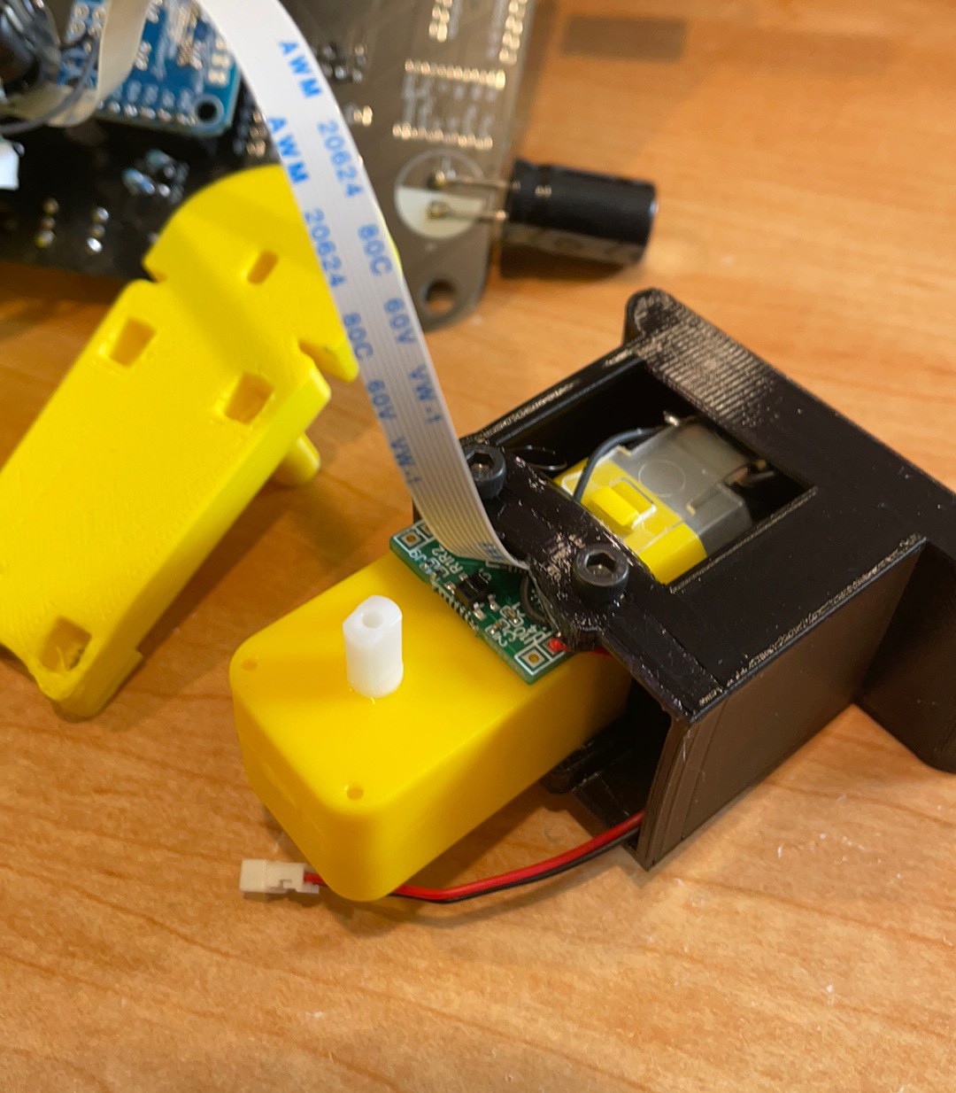
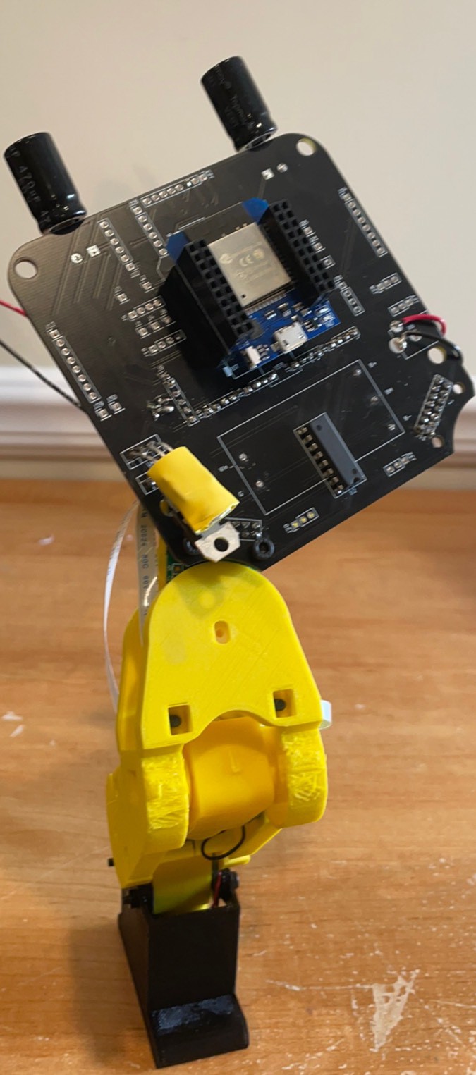
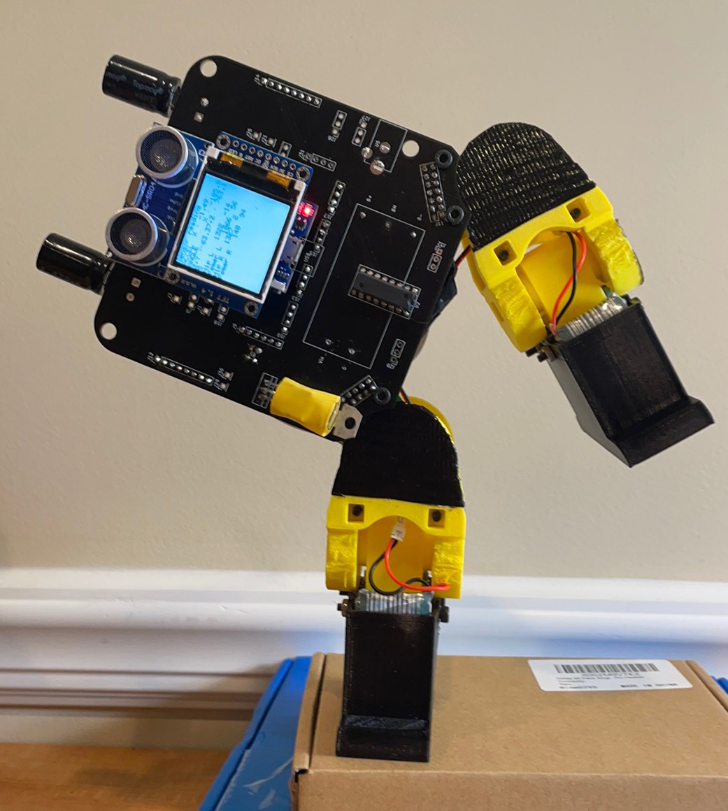
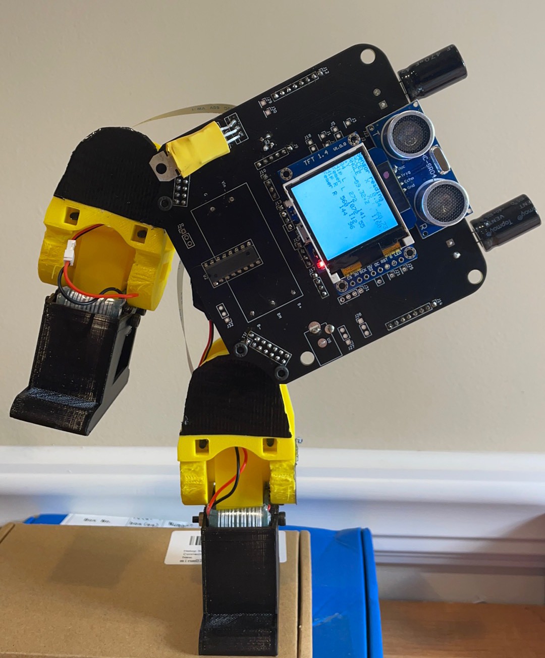
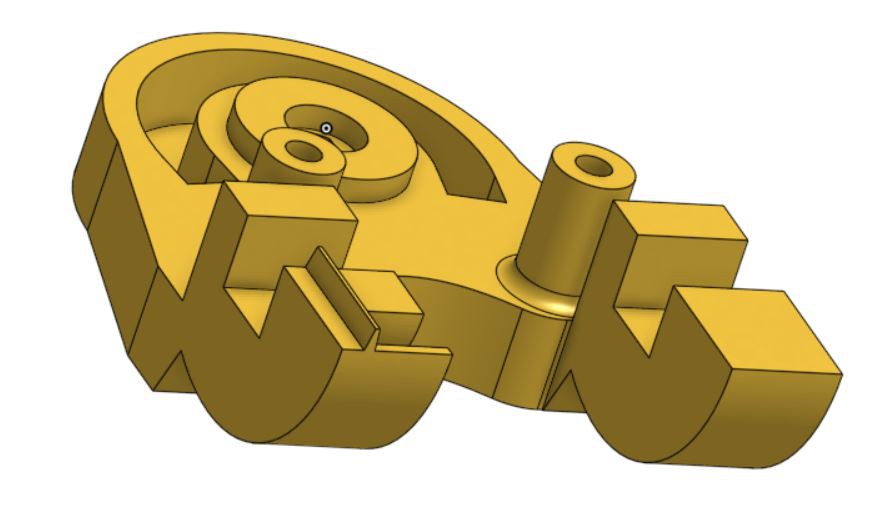
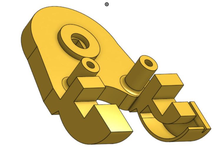
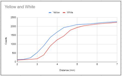
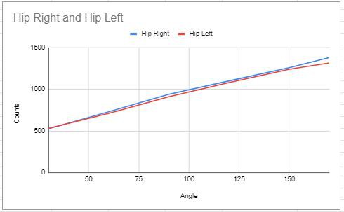
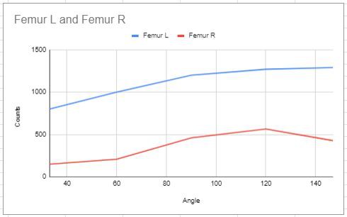
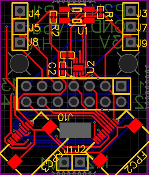
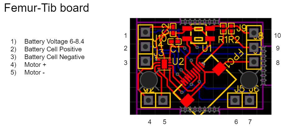
- Designed a cheap driver/sensor board to read the absolute angle of the motor joint and run the motor. Designed a 3D printed connection that use the motors as structural members and use the 3D printed ramps to change the distance from the optical sensor with rotation. Used the worlds most ubiquitous yellow gear motor found in inexpensive projects everywhere. Using extremely common FFC cables to link the legs and the boards for one robot cost 15 dollars and can arrive on your doorstep in 8 days! The boards also have what would normally be the guts of a servo motor, but now are more accessible to the processor which can access the position of the joint at any time.
2) Processor creep. Robots eat IO pins for breakfast.
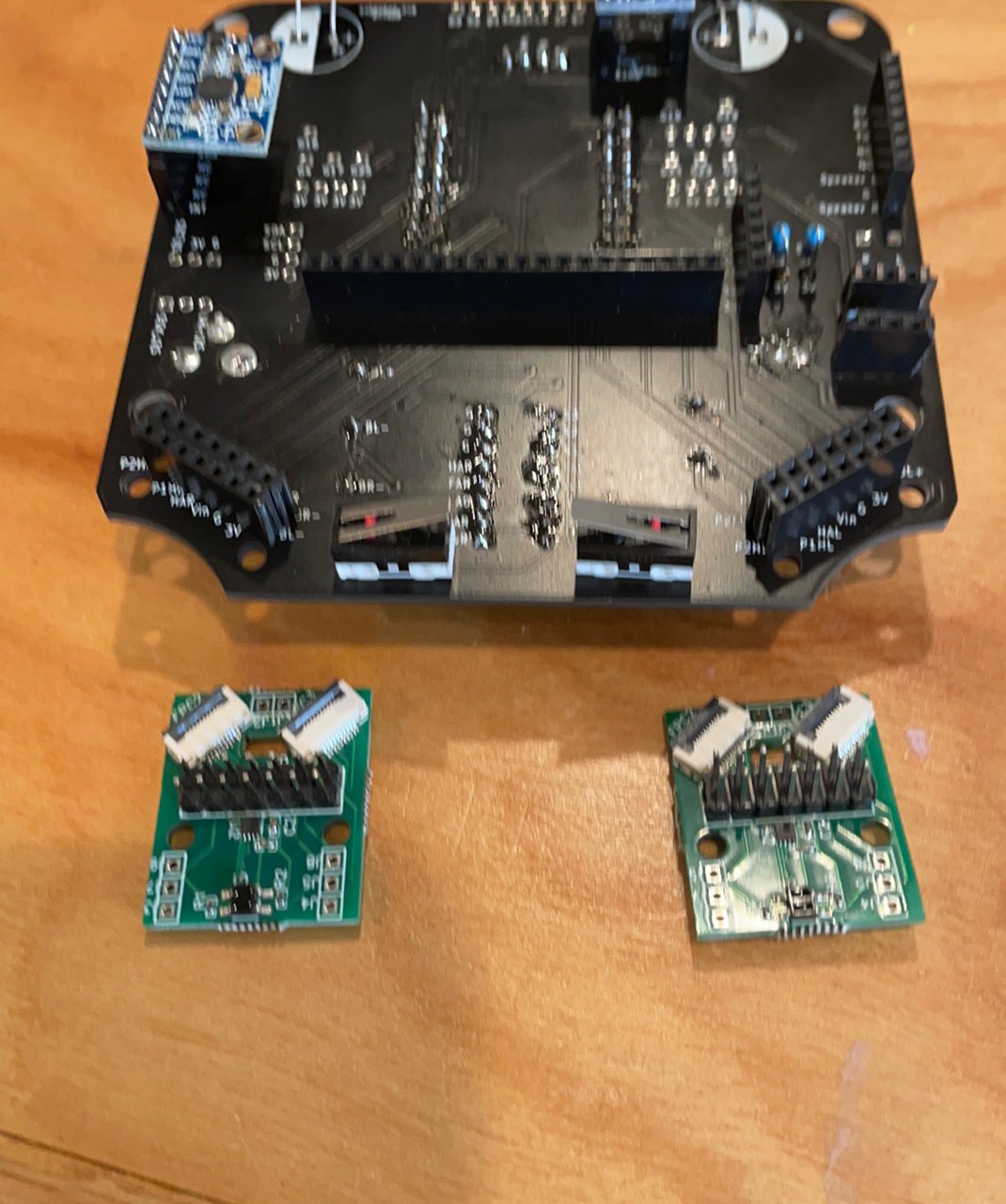
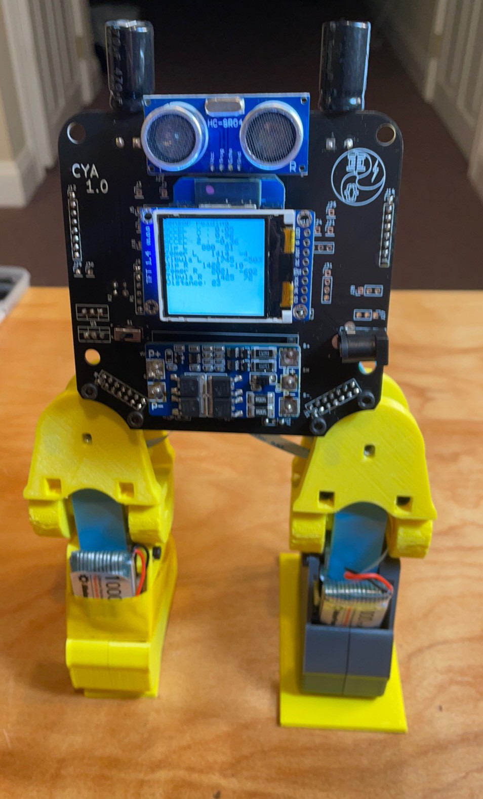
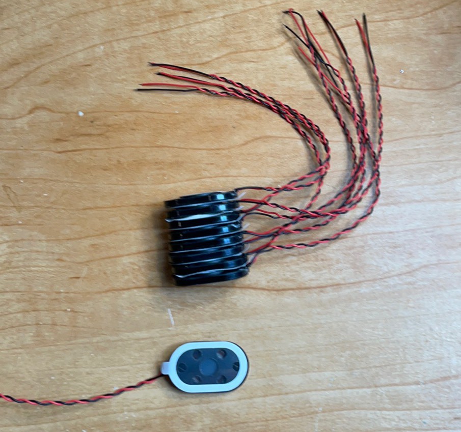
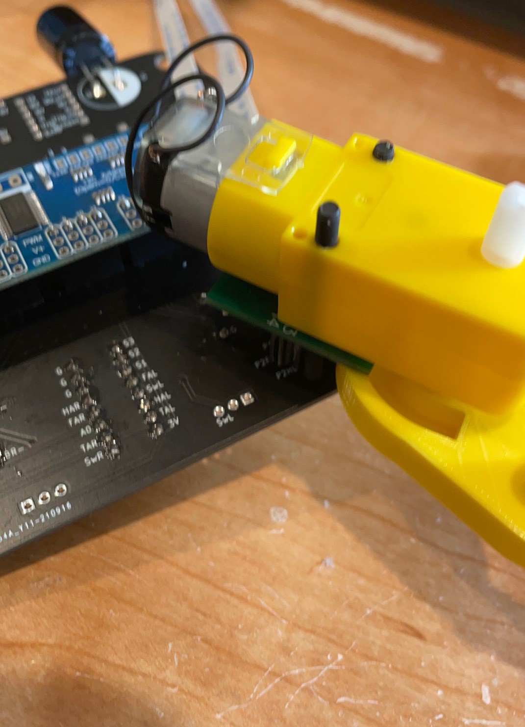
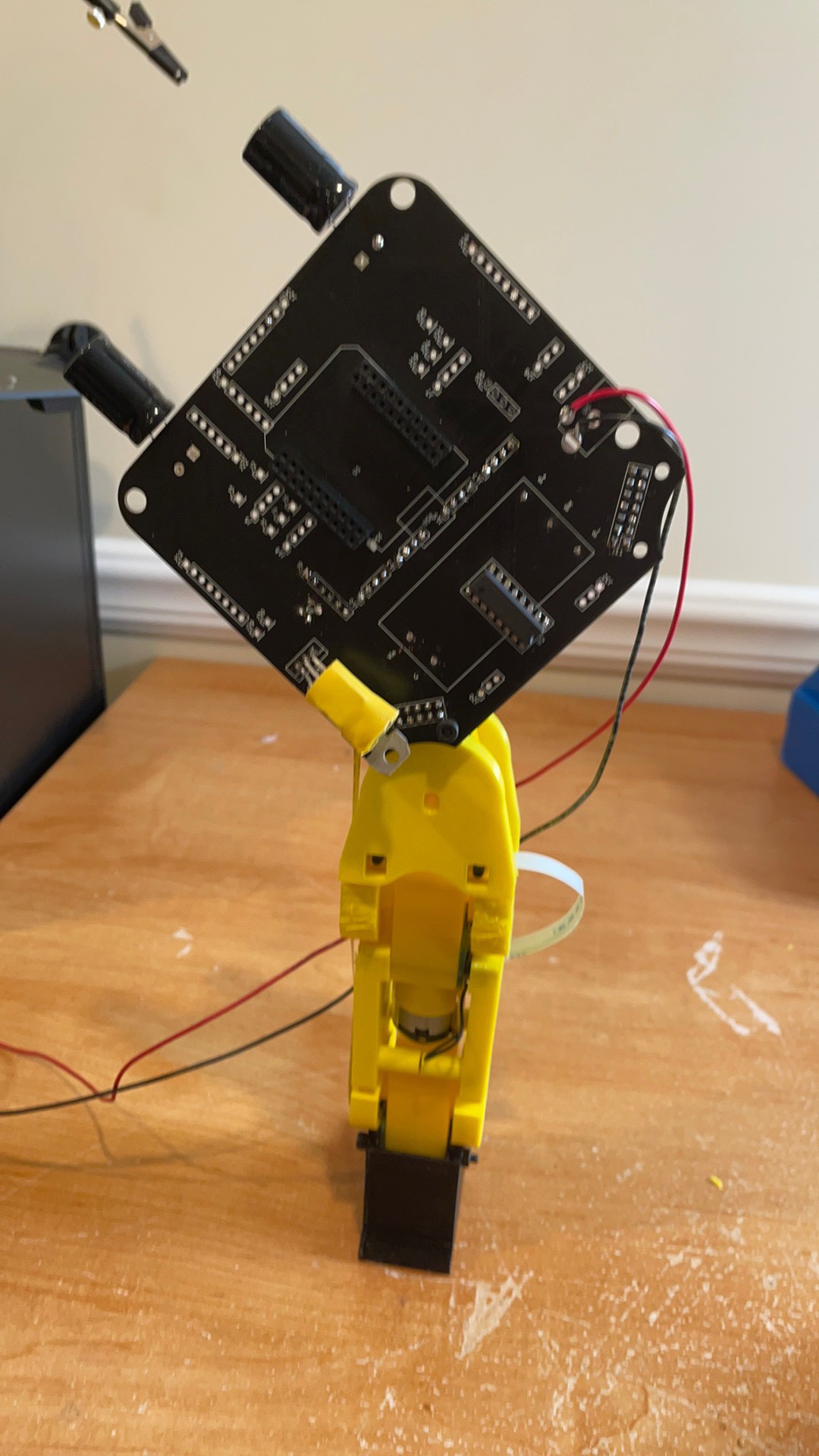
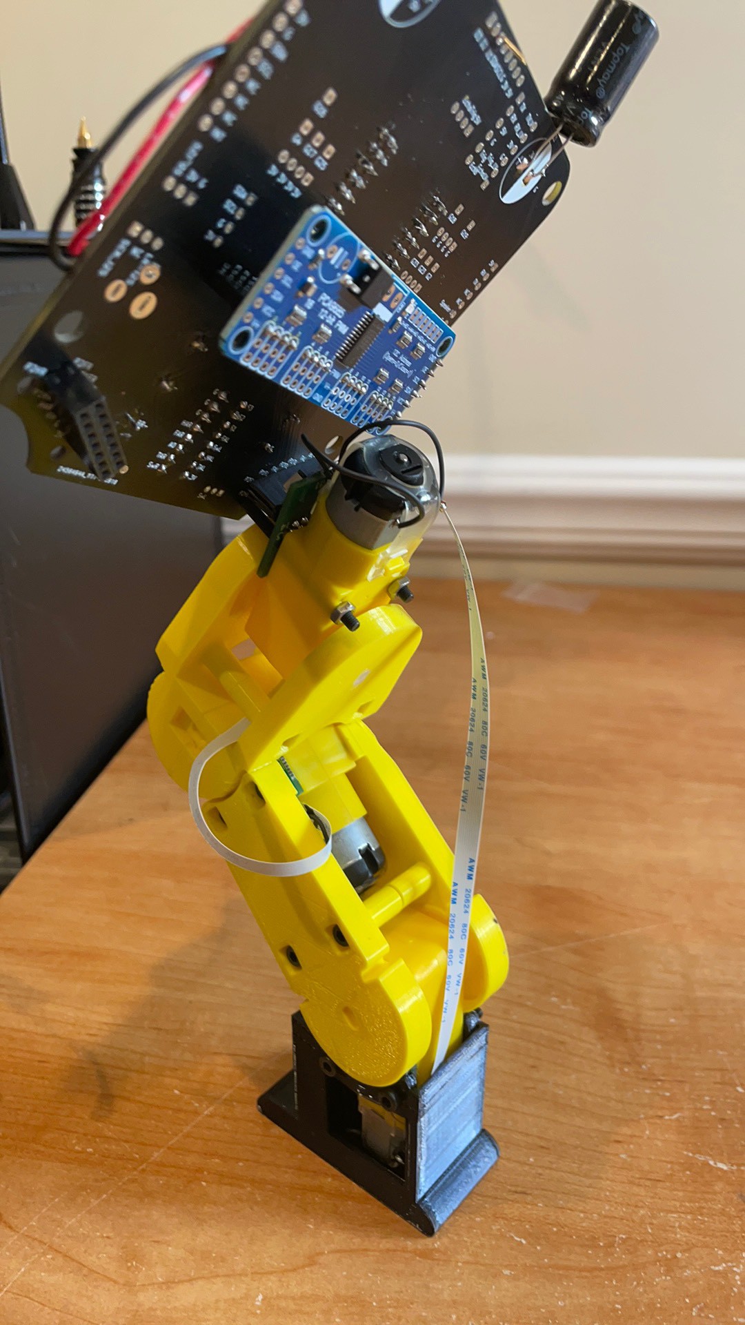
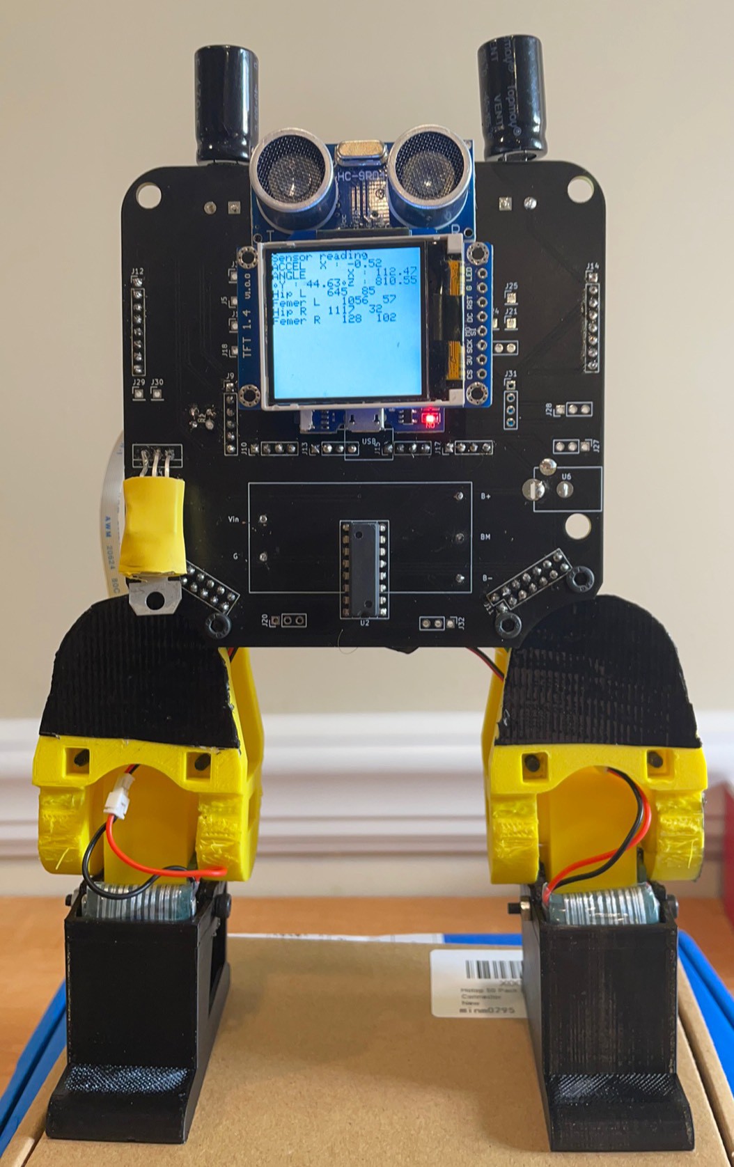
- Used a double demux in which the PCA9685 board is also controlling the analog demux. In this way I can run 6 motor joints and read their position with only two I2C pins and one analog input. This leaves ~20 other IO pins to do range finding, balance, audio out, I2S audio in and many other functions yet to be added. This can all be run with a $5 ESP32. Lastly, it is expandable to allow 3 additional pairs of arms, legs or wings, whatever you may fancy. This is achieved with just adding a daughter board with the PCA9685 expander and the 74HC demux chip.
3) Wires and batteries make a robot ugly and unstable.
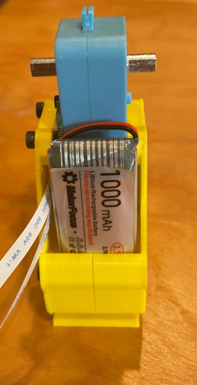
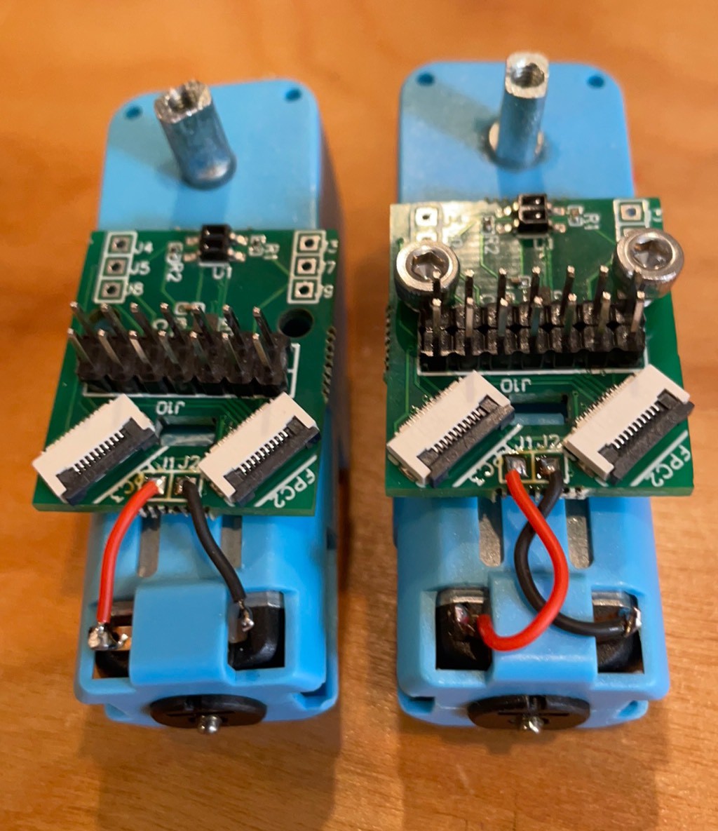
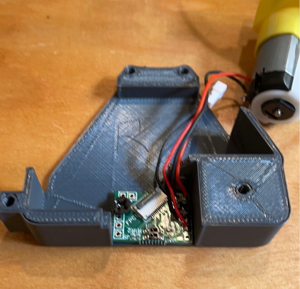
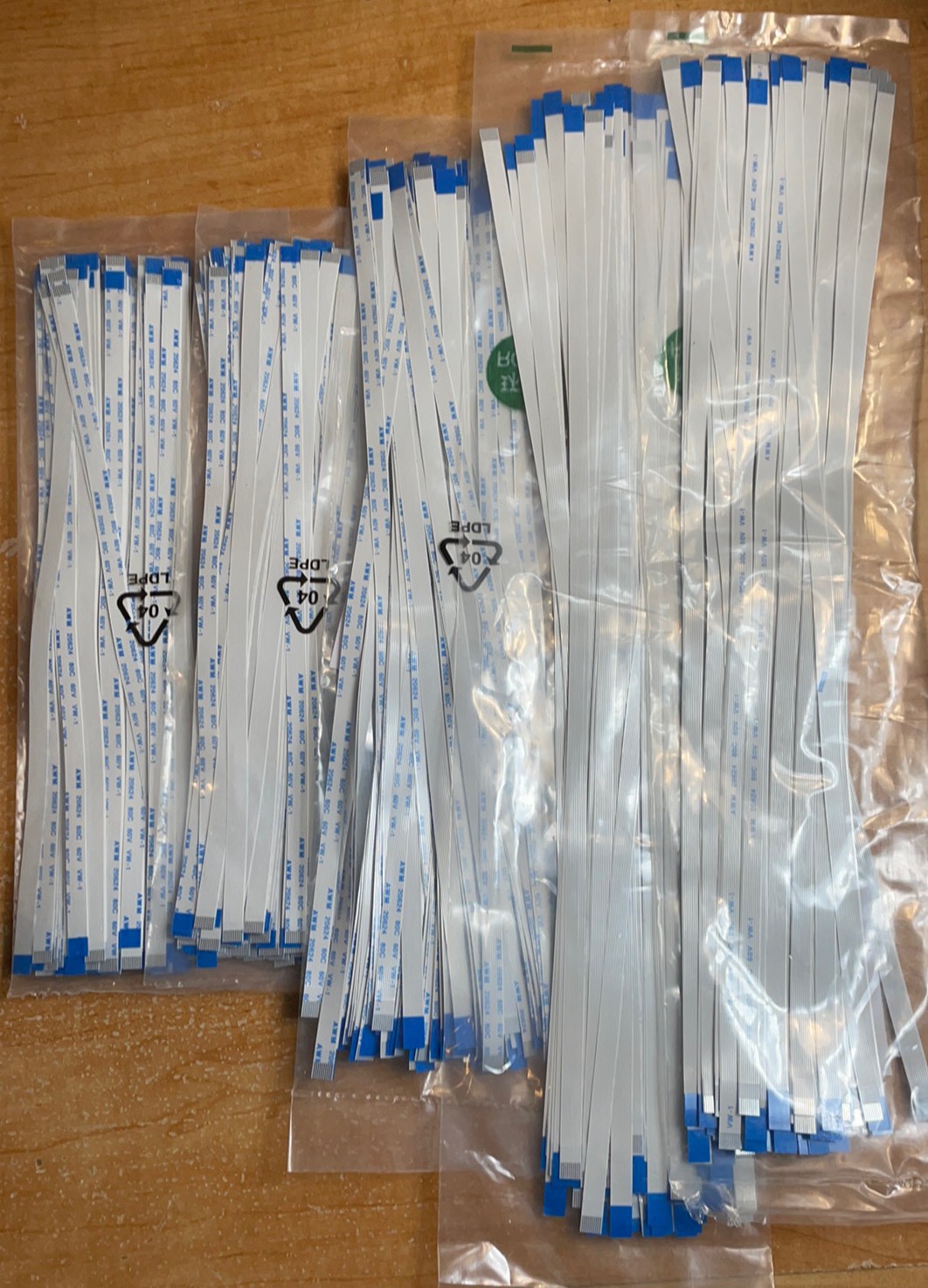
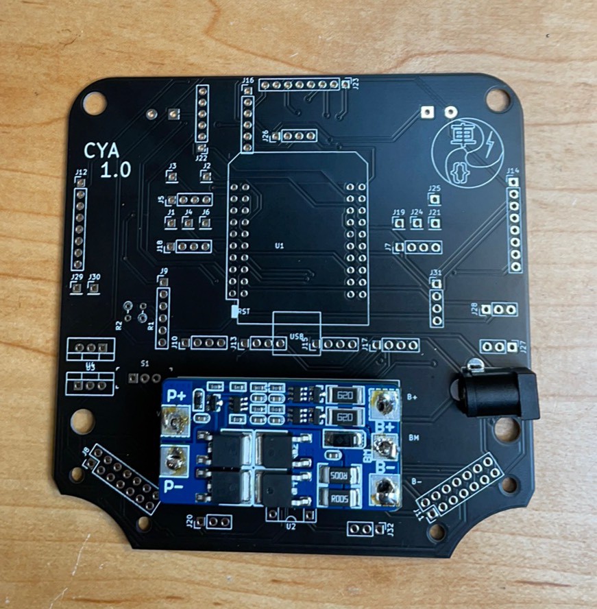
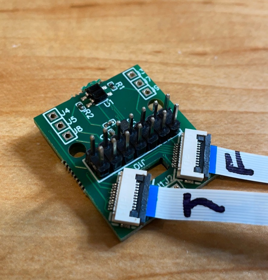
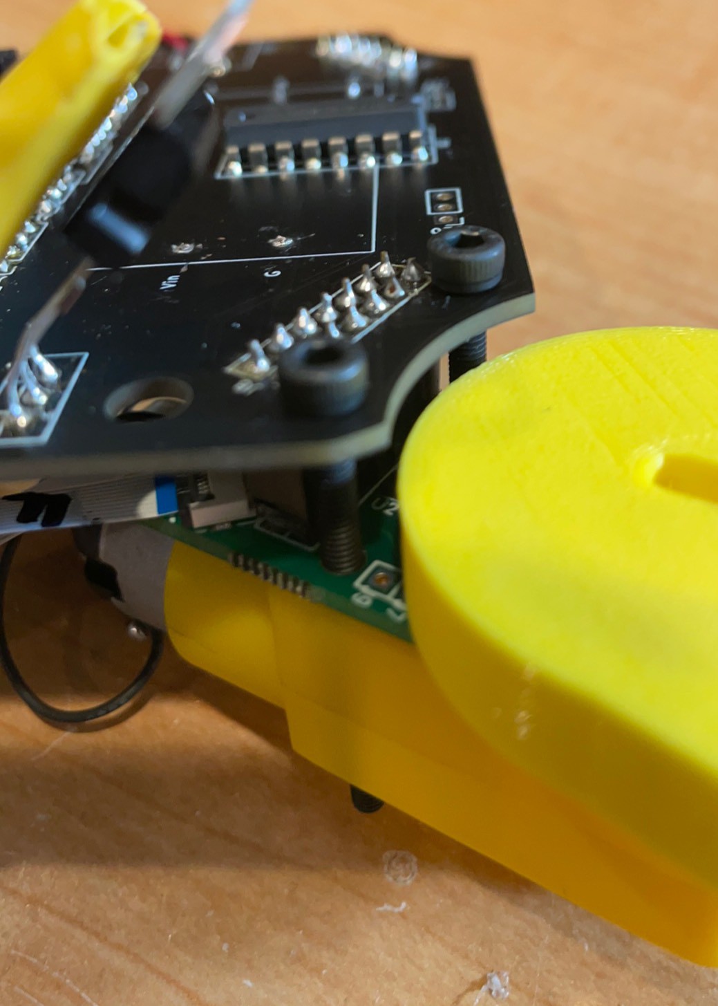
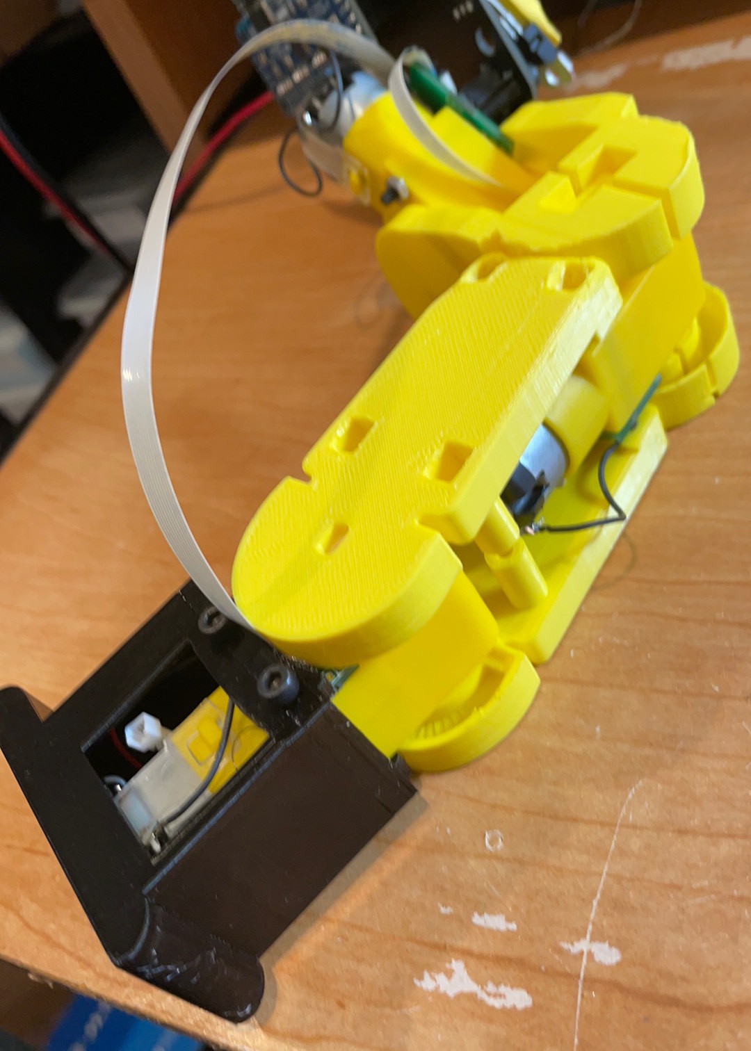
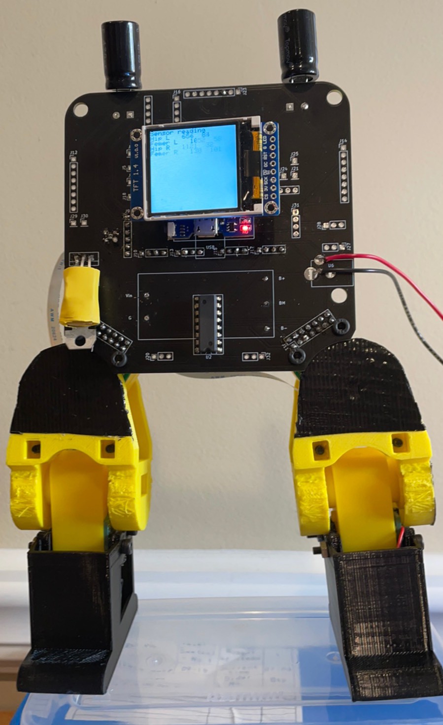
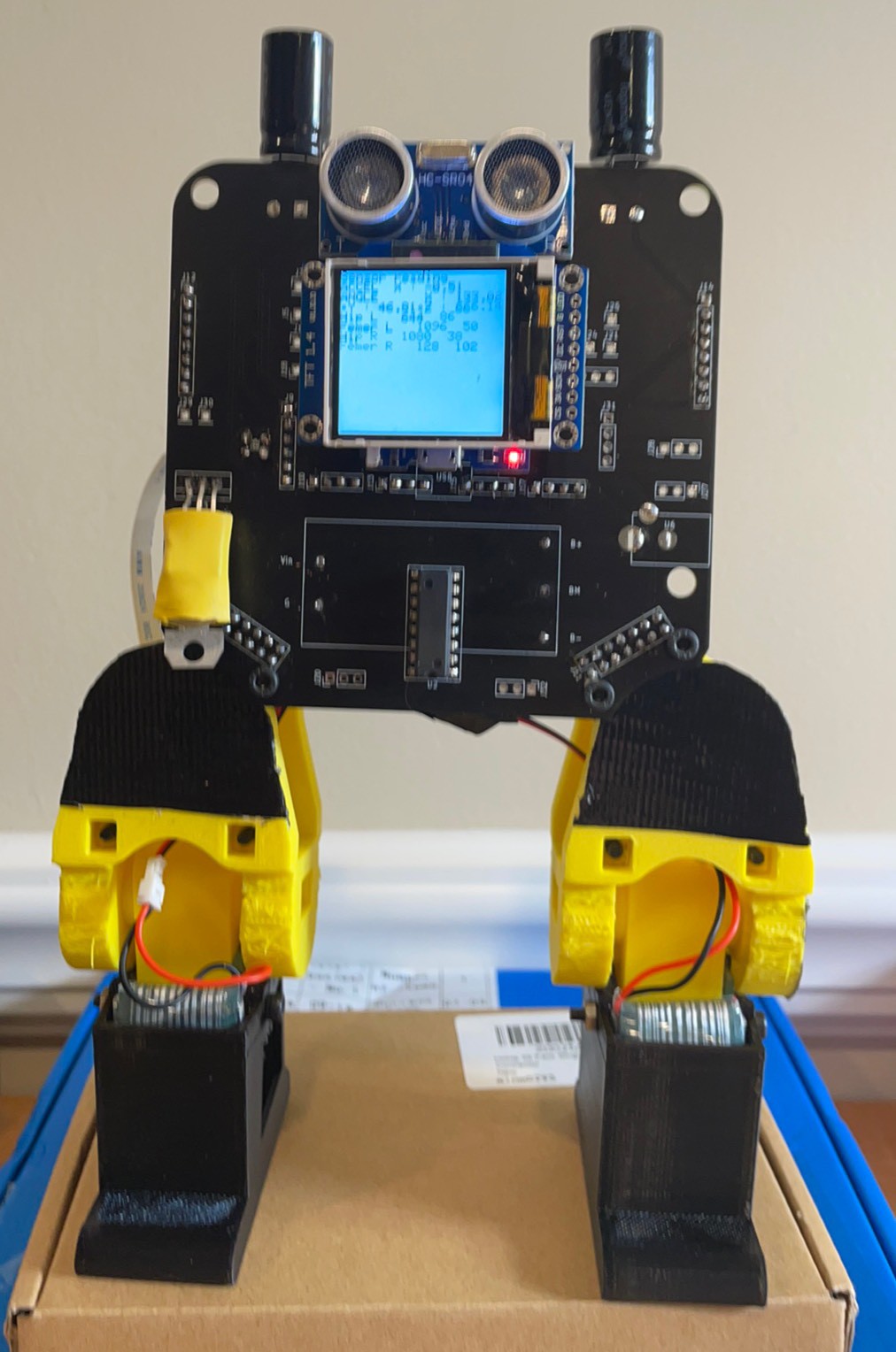
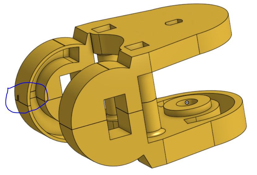
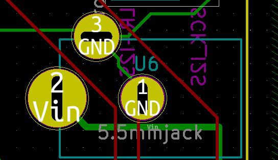
- The last advancement is a unique setup for how to connect the motors and batteries. The legs are connected to the brain board through a double row header so they can easily be exchanged. First hip board with the header has two FFC cables that run down to the Femur and Tibula boards which are common and can connect to the battery. The cables are elegantly threaded though the joints with service loops to allow the legs the full range of motion without risk of the cables being snagged. The batteries, one in each foot to lower the center of gravity, have a separate set of traces that link them in parallel through a BMS in the head board. This allows the motor to be run at 7.4-8.4V and be charged through a 9V adapter plugged into the headboard.
Purpose
Cya was designed to encourage makerspace members to learn about robotics and the tools used to make this Robot. Here are some reasons Cya serves this purpose well.
Designed with maximum availability in mind.
All the electronic components and motors are available on Amazon, mostly with Amazon prime.
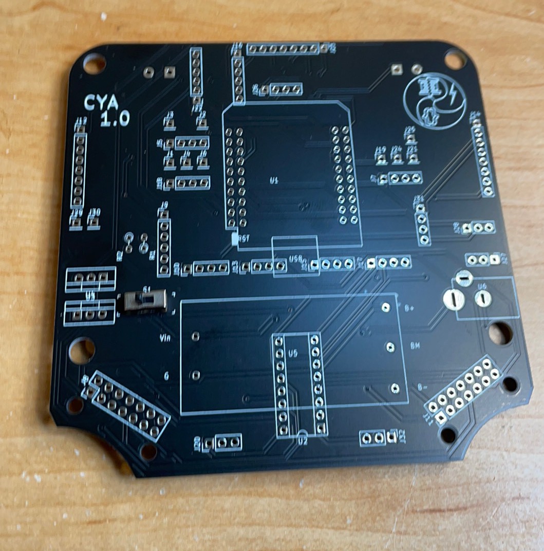
Board files are available and 10 bare headboards and 10 sets of populated leg boards can be ordered from JLCPCB for $150 and delivered in around a week. With some better availability on alternate motor drivers and sensors I expect to be able to cut this in half.
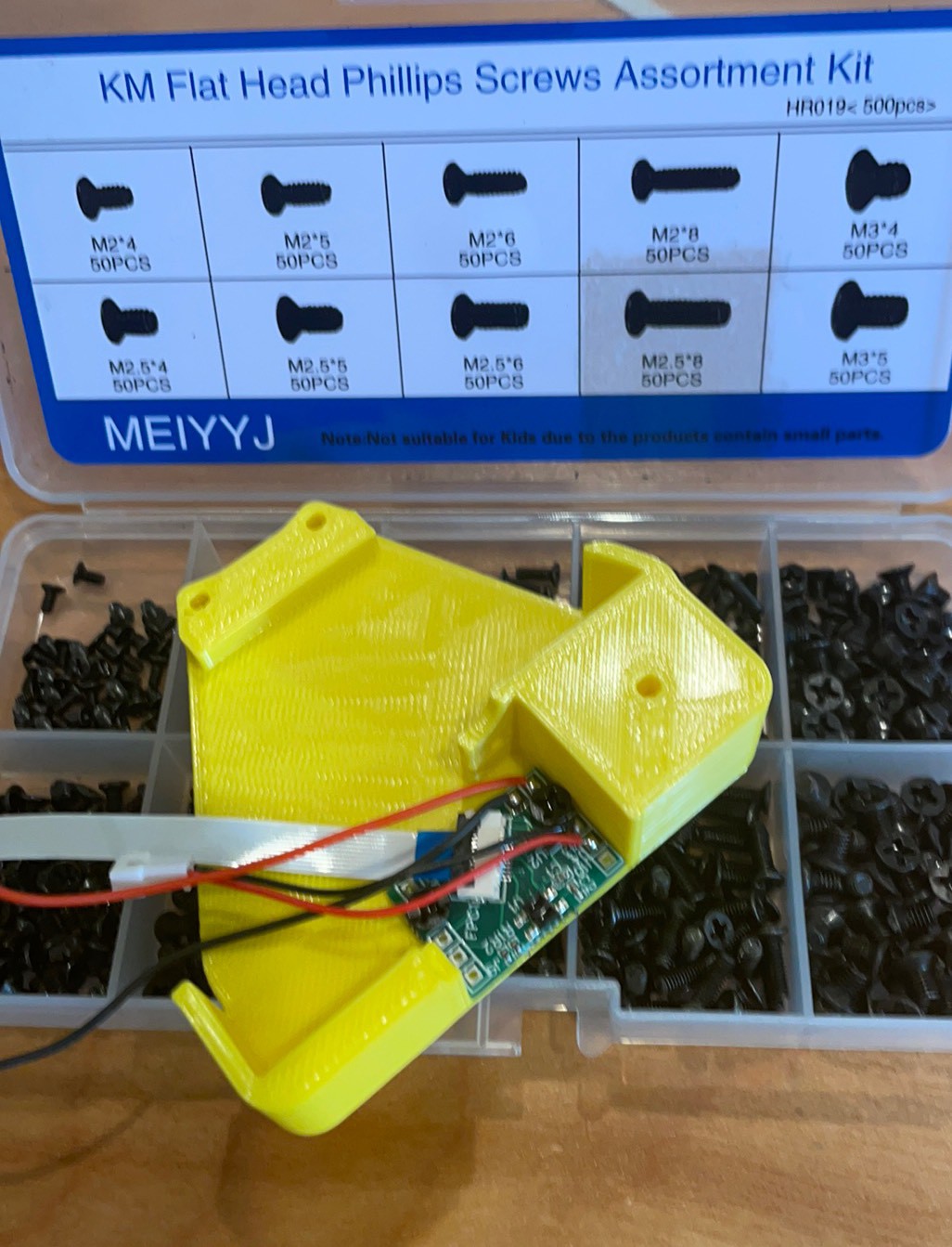
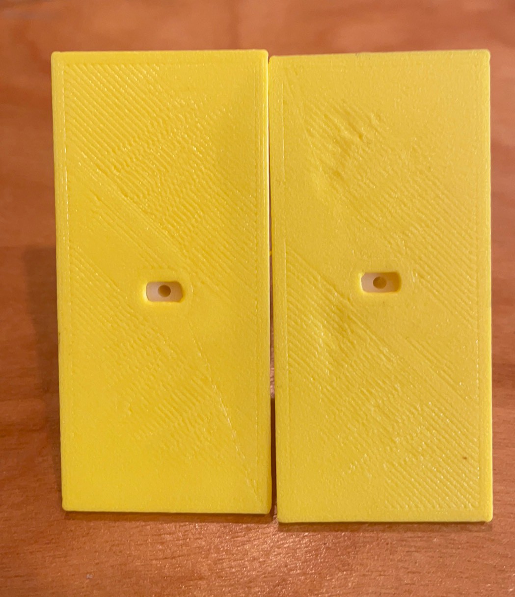
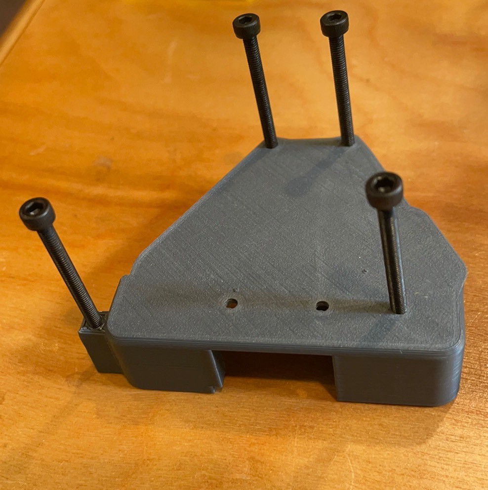
There are eight 3D printed components that make up a leg and two legs can be printed on a$259 Sovol S01 printer in one print job. The filament for the one print job costs less than a $2 and finished in less than a day. Another option might but using a 3D printer at one of the main libraries that now offer them.
The rest of the parts are standard hardware like screws and headers.
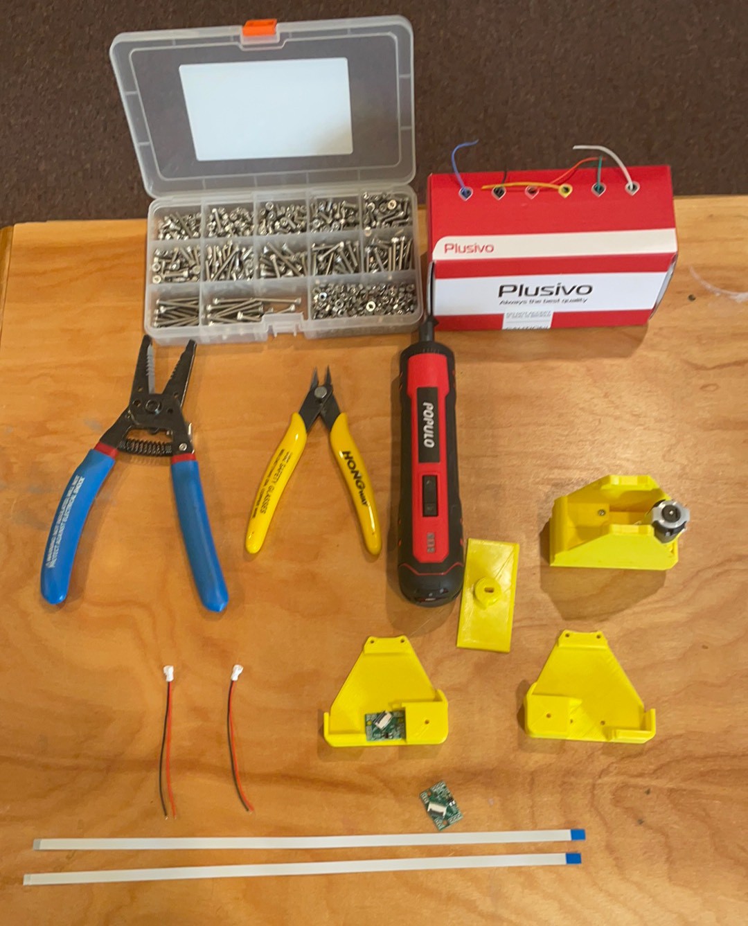
Everything is attached with through hole soldering or connectors. The only tools needed are a soldering iron and a hex driver.
Everything can be run with Arduino to start with. Micro Python modules are being built out and there is a plan for native C in Doxygen using Expressif libraries. There are example sketches and tutorials for most of the modules in Arduino so we stand on the shoulders of giants and this project leverages the open source efforts of the community. A special shout out to Adafruit and the PCA9685 board that Cya is designed around. https://www.adafruit.com/product/815 Their great documentation spurred the idea and got me going....
Read more »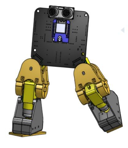


 Alvaro Ferrán Cifuentes
 Ruediger F. Loeckenhoff
 David
David
 Daren Schwenke
I like the circuit board holder in the photo of the voltage regulators in sockets. Are those columns magnetic?