 Ken Yap
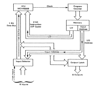
This is the block diagram of the system that is emulated. Not shown are the scratchpad locations for memory, and the FLGF reset line, see description below.
It was relatively easy to write an emulator for the Arduino.
/*
        MC14500B Industrial Control Unit system emulator Version 1
*/

#define DEBUG
#define HALFPERIOD  100 // sets speed of emulation

// All 16 instructions
#define NOPO  0x0
#define LD    0x1
#define LDC   0x2
#define AND   0x3
#define ANDC  0x4
#define OR    0x5
#define ORC   0x6
#define XNOR  0x7
#define STO   0x8
#define STOC  0x9
#define IEN   0xA
#define OEN   0xB
#define JMP   0xC
#define RTN   0xD
#define SKPZ  0xE
#define NOPF  0xF

struct icu {
  byte  counter;        // current instruction
  byte  clock;          // code executed on low phase
  byte  rr;                 // access to I/O address 0 goes here
  byte  flg0;
  byte  flgf;
  byte  ien;
  byte  oen;
  byte  jmp;
  byte  rtn;
  byte  skpz;
} icu;

const byte code[256] = {
#include "code.h"
};
byte rwmem[8];
const byte iportmap[8] = { 0, 2, 3, 4, 5, 6, 7, 8 };
const byte oportmap[8] = { A0, A1, A2, A3, A4, A5, 9, 13 /*LED*/ };

byte read(byte addr) {
  if (icu.ien == 0)
    return 0;
  byte port = addr & 0x7;
  return addr & 0x8 ? rwmem[port] : (port == 0 ? icu.rr : digitalRead(iportmap[port]));
}

void write(byte addr, byte data) {
  if (icu.oen == 0)
    return;
  byte port = addr & 0x7;
  if (addr & 0x8)
    rwmem[port] = data;
  else
    digitalWrite(oportmap[port], data);
}

void setup() {
  // put your setup code here, to run once:
#ifdef DEBUG
  Serial.begin(115200);
#endif
  memset(&icu, 0, sizeof(icu));
  icu.ien = icu.oen = 1;
  for (byte i = 1; i < sizeof(iportmap) / sizeof(iportmap[0]); i++)
    pinMode(iportmap[i], INPUT_PULLUP);   // means unconnected pins will be 1
  for (byte i = 1; i < sizeof(oportmap) / sizeof(oportmap[0]); i++)
    pinMode(oportmap[i], OUTPUT);
}

void loop() {
  // put your main code here, to run repeatedly:
  for (icu.counter = 0; ; icu.counter++) {

    icu.clock = 1;              // high phase, fetch
    byte c = code[icu.counter];
    byte instr = c >> 4;
    byte addr = c & 0xF;

#ifdef DEBUG
    Serial.print(icu.counter, HEX);
    Serial.print(" ");
    Serial.print(c, HEX);
    Serial.print(" ");
    Serial.println(icu.rr, HEX);
#endif

    delay(HALFPERIOD);

    icu.clock = 0;              // low phase, execute

    // on flgf jump to beginning of program
    if (icu.flgf) {
      icu.flgf = 0;
      icu.counter = 255;
      continue;
    }
    icu.flg0 = icu.flgf = 0;    // reset flags

    // todo: deal with jmp and rtn
    if (icu.skpz) {             // skip instruction
      icu.skpz = 0;
      continue;
    }

    icu.jmp = icu.rtn = icu.skpz = 0;   // reset control flags

    switch (instr) {
      case NOPO:
        icu.flg0 = 1;           // currently no-op
        break;
      case LD:
        icu.rr = read(addr);
        break;
      case LDC:
        icu.rr = !read(addr);
        break;
      case AND:
        icu.rr &= read(addr);
        break;
      case ANDC:
        icu.rr &= !read(addr);
        break;
      case OR:
        icu.rr |= read(addr);
        break;
      case ORC:
        icu.rr |= !read(addr);
        break;
      case XNOR:
        icu.rr ^= !read(addr);
        break;
      case STO:
        write(addr, icu.rr);
        break;
      case STOC:
        write(addr, !icu.rr);
        break;
      case IEN:
        icu.ien = icu.rr;
        break;
      case OEN:
        icu.oen = icu.rr;
        break;
      case JMP:
        icu.jmp = 1;
        break;
      case RTN:
        icu.rtn = 1;
        break;
      case SKPZ:
        icu.skpz = 1;
        break;
      case NOPF:
        icu.flgf = 1;
        break;
    }
    delay(HALFPERIOD);
  }
}
And the first test program is:
// Test program: LD 1; AND 2; STO 3; STOC 7; NOPF;
// Input pins are pulled high by default so
// grounding either pin D2 or D3 should turn on LED
0x11, 0x32, 0x83, 0x97, 0xF0
Relevant points about this design
The program storage (PS) is 256 bytes so the program counter is 8 bits wide. Each instruction and operand fits in a byte, the 4 MSBs are the instruction and the 4 LSBs are the address. As mentioned before, the program counter is not on-chip, it has to be provided externally. It is incremented by the clock signal. In the high phase, the code nybble is read in and in the low phase, it is executed, making use of the address nybble if necessary. The clock variable is only written to and never read so it's redundant, but I find it useful to use this as documentation to read the timing diagrams in the handbook.
(An interesting diversion is to ask whether this is a small endian or big endian design. In this design both nybbles are read in one go, so it has no endianess. But in the case of 4-bit wide PS where the code nybbles are interleaved with the address nybbles, using the clock as the LSB, you can see that since the code is read when clock == 1, this means the address nybble precedes the code nybble so it's little endian.)
4 bits for the address means we can potentially address 16 input ports and 16 output ports, distinguished by the write line. The top 8 addresses are directed to RW memory, so we have only 8 each of input and output ports. In addition, on the Arduino, output port 7 is directed to the builtin LED so that we can control it from a program.
Execution starts at program byte 0 and wraps around after 255. So in the simplest design, all of the PS is executed repeatedly. How do we make sure that trailing bytes after the desired code don't do anything untoward? There are two ways:
Firstly the codes 0x0 (NOPO) and 0xF (NOPF) are both no-ops, the reason being that the blank state of PROMs in that era were either all 1's or all 0's. But note that this doesn't change the cycle length, it just executes no-ops until the counter wraps around. This is when execution speed is not critical.
The second way is to use the fact that NOPO and NOPF generate a pulse at the respective pin when executed. In this design we use the NOPF pulse to reset the counter to 0, thus jumping to the beginning of the program. This will shorten the cycle length.
The IEN and OEN instructions are used to disable input and output for sections of code. This method of conditional execution also doesn't change the cycle length. We haven't implemented JMP, nor RTN and SKPZ. These require extra hardware. For example JMP implies external hardware to load the program counter from the address. And the address would have to be wider to cover the PS space. Not for this version.
Discussions
Become a Hackaday.io Member
Create an account to leave a comment. Already have an account? Log In.
Okay
Are you sure? yes | no
Hi Ken,
If your looking for a couple of MC14500B's I have some collecting dust.
Regards AlanX
Are you sure? yes | no
Thanks, but I'd like to follow my procedure for self-education. I think you should hang on to yours. They might become collector's items.
Are you sure? yes | no