 Mitsuru Yamada
1. System requirements
The CPU of the computer to be run is the 6502, which was widely used about 45 years ago. The total memory requirement for the system and user area is 16kB. The user interface uses a RS232C serial terminal. Figure 1 shows the execution of this interpreter CI-2 (Computation Interpreter -2).
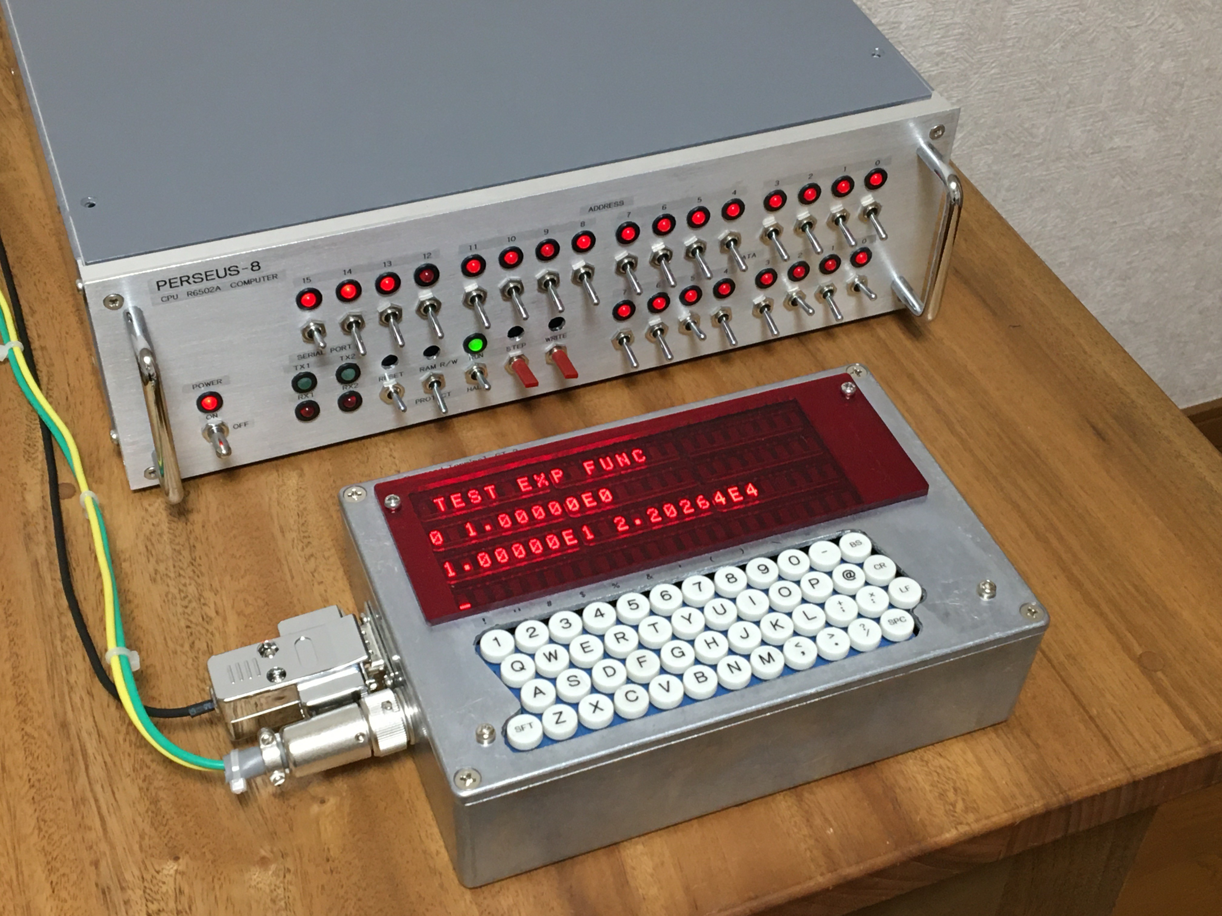
Fig.1 Floating point interpreter CI-2 running on my 6502 computer PERSEUS-8
2. Language specification
The language specifications are listed in the following. This specification was not defined exactly at the beginning, but was the result of trial and error. The details of the language specification are shown in the attached file (Specification of Floating Point Computation Interpreter CI-2 V2_0.pdf).
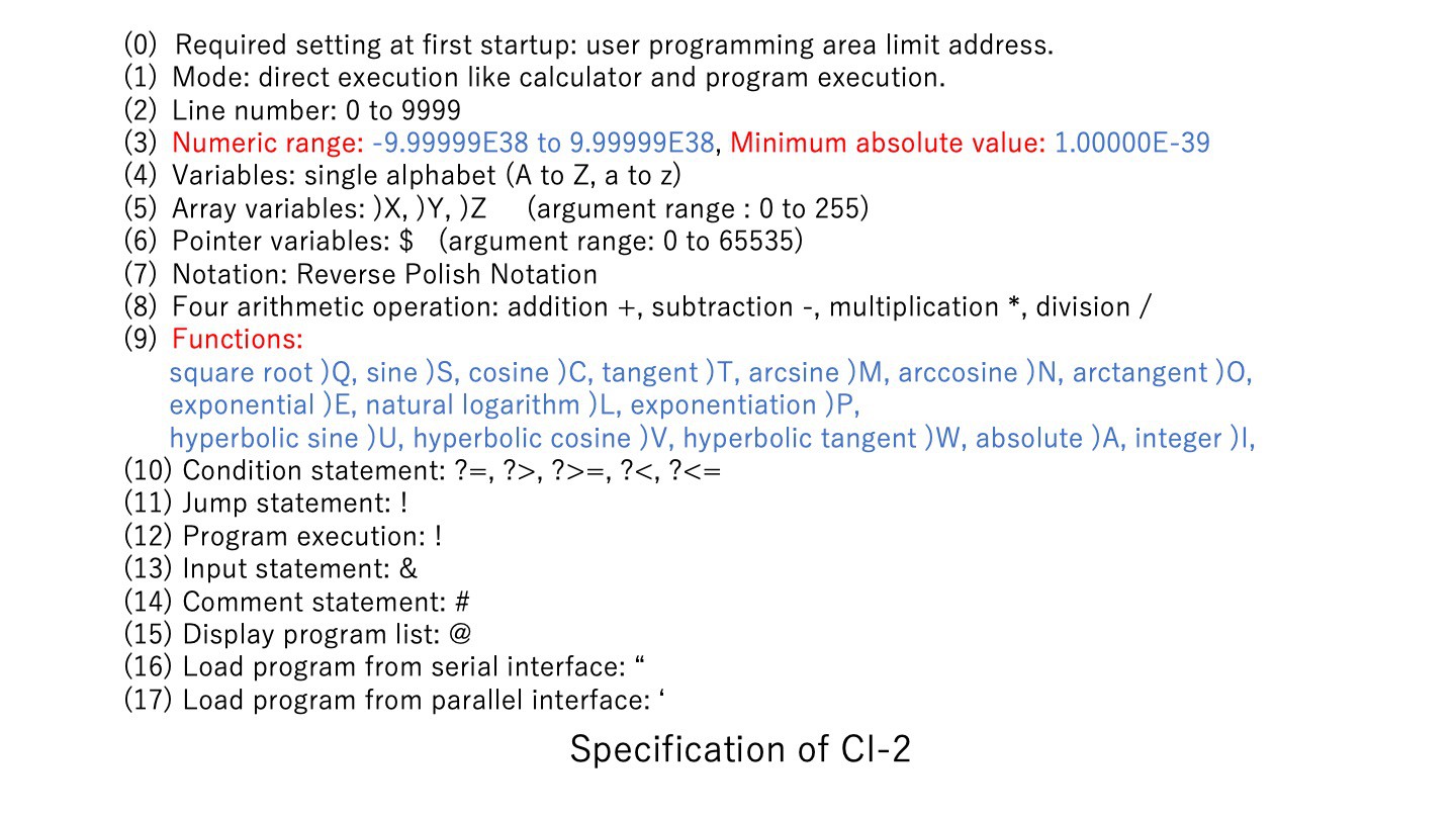
The numeric values were set to 32-bit single-precision floating-point type. In order to simplify the conversion of ASCII code to numbers, BCD notation was used instead of binary. Therefore, the number of significant digits and the numerical range are inferior to those of general single-precision arithmetic systems. In order to avoid parsing, variables and instructions were defined as single letters of the alphabet. The formula uses RPN (Reverse Polish Notation). This is also to avoid parsing.
There are three one-dimensional array variables:)X,)Y,)Z. The arguments range from 0 to 255. This alone occupies 3kB of memory. There is no statement equivalent to a FOR loop, but I decided to use a conditional branch and a jump to the specified line number instead. Therefore, it is not suitable for large-scale programming.
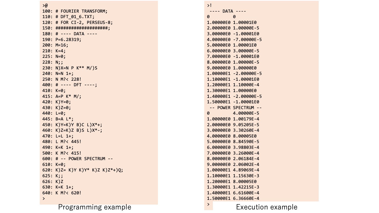
The following is an example of programming description and its execution. The line number 230 ‘N)X=N P K** M/)S’ is ‘X(N)=sin((K*P*N)/M)’ in a typical language description. The line number 480 ‘L M?< 445!’ means ‘if L<M then go to 445’. Command ‘@’ from the terminal is the display of the program list, and command ‘!’ is to execute the program.
The upper limit of the user program area is set by manually writing to the zero-page area only at the first startup so that it can be varied according to the memory capacity of the system. In PERSEU-8, the memory limit is $1FFF, so type 130$=31 in the direct mode pointer variable. This will set the upper byte $1F of the upper memory limit address in the register $0082. In PERSEUS-8, the user memory area is 4 kB, so the maximum number of characters in a user program is approximately 3840
3. Software configuration
Figure 2 shows the block diagram of this interpreter system. The system will wait for one line of input after startup. After inputting a single line from the serial interface, it analyzes it one character at a time from the left of the line buffer. Here, if a line number is detected at the beginning of a line, the process moves to the line editor. If no line number is detected, parse one character at a time as direct execution mode. This ‘MAIN LOOP’ process is mapped from address $E8F0 in the assembly code. If it is a number, it is converted to BCD and stored in the floating point register. This ‘GET FLOATING POINT’ process is mapped from address $E0F7 in the assembly code. If it is an arithmetic operator or a command, it moves to the respective processing routine. If a ‘CR’ code is detected, perform the assignment and register value display, and return to waiting for one-line input. This ‘END LINE’ process is mapped from address $EDB9 in the assembly code.
Program execution is performed by setting the execution flag upon detection of a ‘! ‘ code and the execution flag is set. Once the execution flag is raised, a single line of analysis is executed from the beginning of the program area. In the case of a conditional branch statement, the line with the line number...
Read more »


 will.stevens
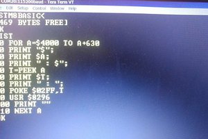
 rogerdipaolo
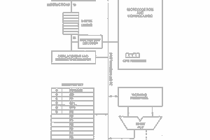
 Keith
Keith
 Michael Wessel
As always, this is an excellent presentation from you. I will have to sit quietly and study it further. Thanks !