Close
0%
0%

Robotics Ground Control Station

Yet another overkill project. An attempt at building a portable and versatile GCS for robotics.

Similar projects worth following
After making the Cablecam, I saw the need to have a portable and customizable controller for that one and other robots to come. One unit that could integrate a computer, inputs and communications hardware would be beneficial for robotics development and deployment.

Wanted to make something neat, and got inspiration from other professional GCS. I have always been fascinated by these. If you google GCS, you'll find [extremely not] similar products.

This was an overkill for the use I'd give it, and was made purposely for future robots I would build, especially for an oncoming project that would benefit from it. Hopefully it can serve as inspiration and a base for people to build upon. I got to practice and learn a few things on the way.

This project has been selected as one of the 50 finalists in the Hackaday Prize 2021! A huge thank you to everyone that has supported the project in any way, and thank you to Hackaday for this incredible honor.


Robotics Ground Control Station Promotion video for Hackaday Prize 2021 finals


You can check the project logs for more detailed information.

Useful resources:

Before you start reading, let me tell you this was a huge overkill for the use I'd give it. The project objective wasn't only the product itself, but the process is something I enjoy and value very much.

Introduction

"UAV ground control station (GCS) is a land- or sea-based control centre that provides the facilities for human control of Unmanned Aerial Vehicles." - Wikipedia

Although I like the definition given above, it is specific for UAVs and I wouldn't limit this project only to UAV control, but also unmanned ground vehicles (UGV), among others.

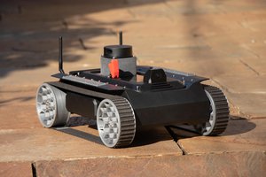
The idea to make something like this came up when working on a previous personal project, the Cablecam. I saw the necessity to have a customizable, portable controller with enough power to run some over-average tasks such as inference using neural networks and at the time I made the following station.

It was simple, consisted of a Nvidia Jetson Nano as the main brains, a 7" screen and two small wireless adapters (2.4GHz). When in use, I connected an Arduino to allow for inputs such as a potentiometer. It served its purpose, it allowed me to control the cablecam, receive a video feed and a bit of telemetry. It also ran inference on the video feed to detect persons in the frame and follow them. The whole thing was implemented in Python. It worked, but it was somewhat sketchy.

The main issue with this base station is it was impractical, each time I went to use it I had to bring a keyboard, an AC wall adapter, the Arduino (it wasn't installed inside due to space restrictions), and if I wanted to add more user inputs (joysticks, buttons, etc), it would become unusable. The wireless communication worked, but was a bit poor due to the WiFi adapters being low power and working in 2.4GHz (this frequency range is the one in which most WiFi networks work, Bluetooth, and microwave ovens too). It served its purpose, but I could do better.

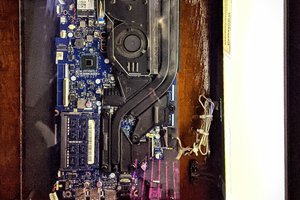
To solve the issues with my previous attempt at a base station, I wanted to make something that had more of a finished product kind of feel, and due to my inability to make a dense integration of components, it should be bigger. It would use the same computer (Jetson Nano) and screen, but hopefully operate in a different frequency in the unlicensed or free use spectrum. It would have many integrated inputs such as joysticks, switches and buttons. To allow for easy interfacing it should have at least a couple USB ports and an RJ45 easily accessible.

Design

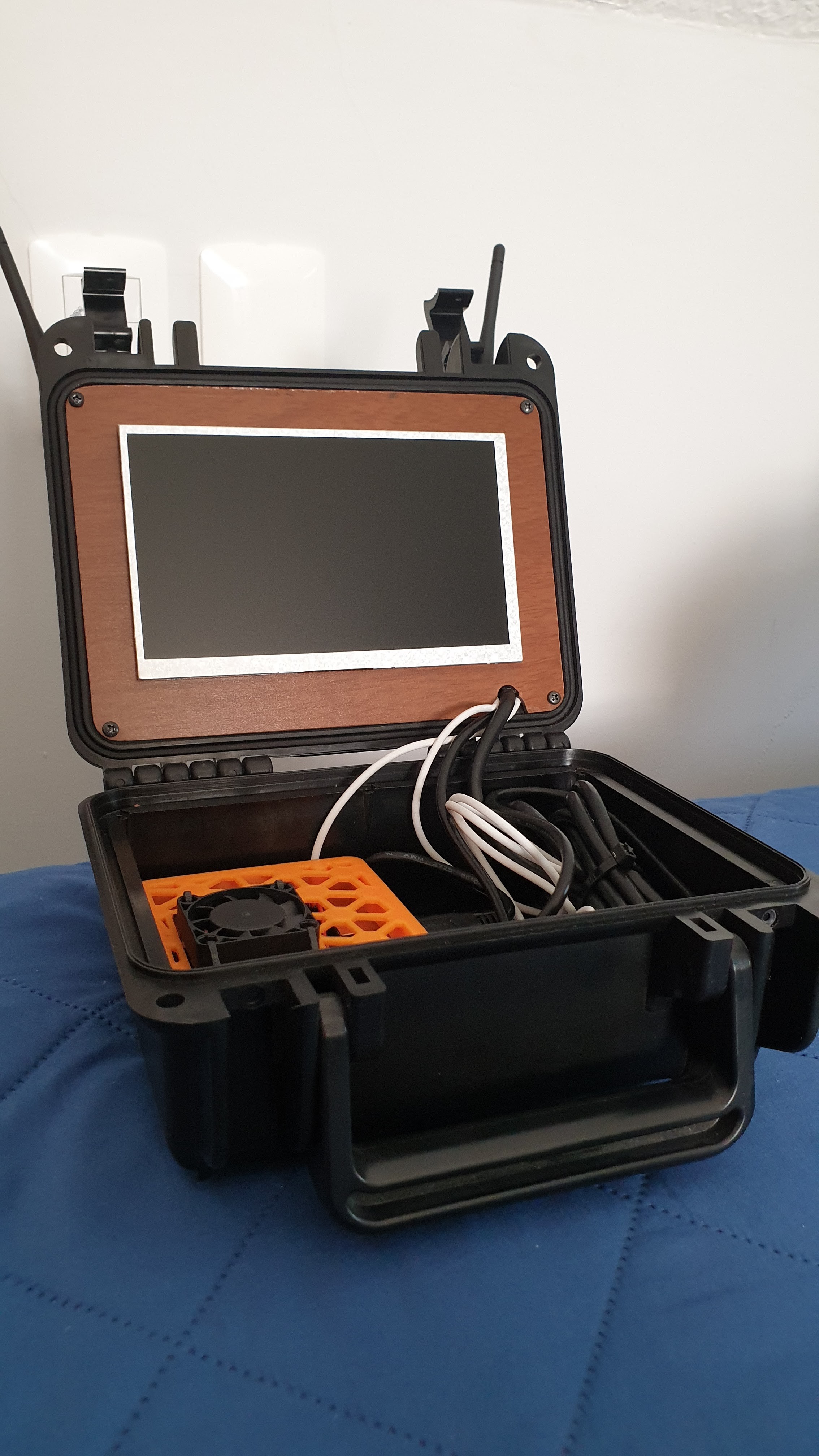
For this project I never considered anything else but a rugged, hard case. I wanted something simple, but functional and good looking. I had at my disposal a 3d printer at home and a CNC cutter at school, so having those manufacturing methods in mind, I got to work. Once I gathered all the components, I measured them and started designing.

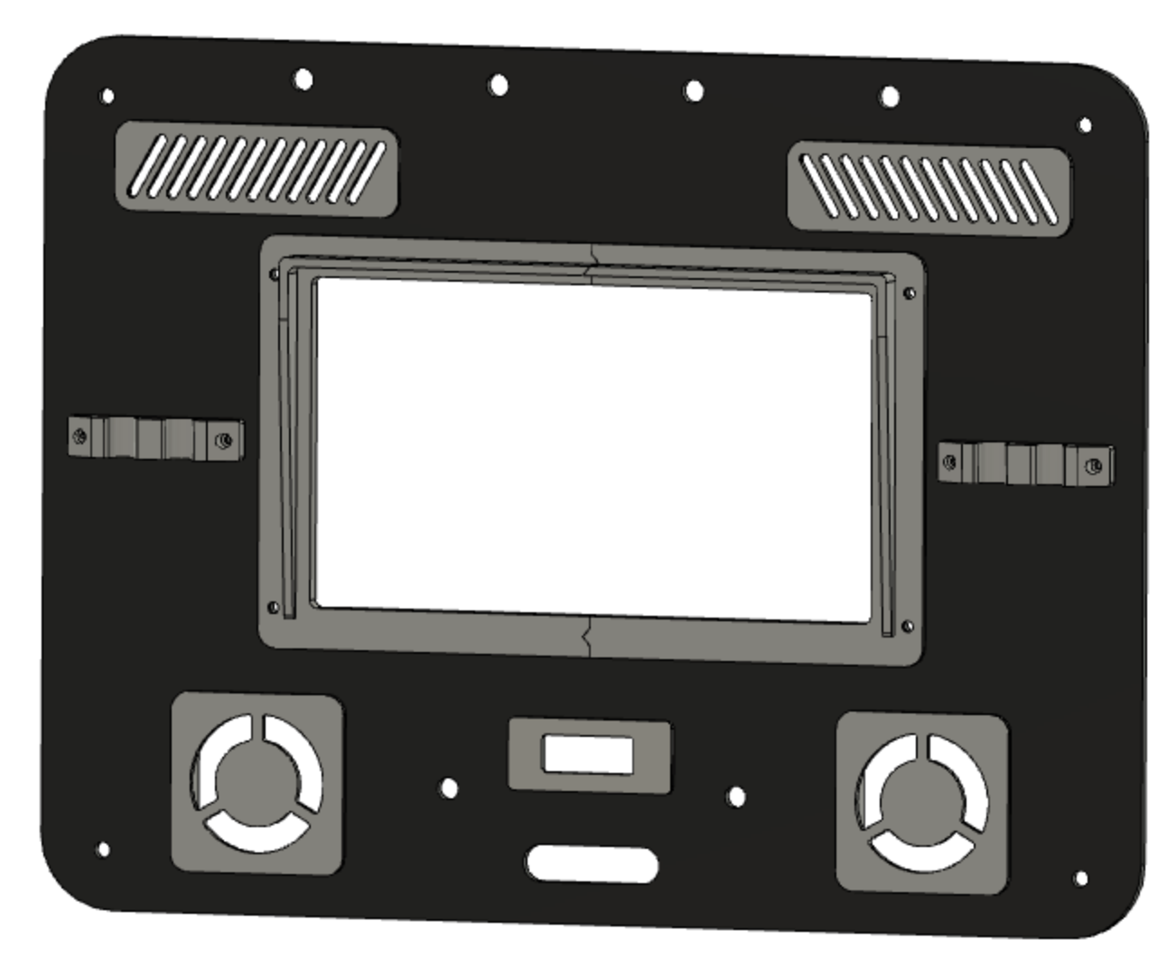
The hard case has much less space on the lid, so most components were placed on the bottom part. The lid holds a 7" screen, the two wireless adapters with respective power switches and antenna connectors, an auxiliary 0.91" OLED display, cooling fans and vents, and antenna holders.

On the bottom piece I went for a stack design, having multiple panels stacked to allow for...

Read more »

CAD files.zip

All the CAD files for the designed parts.

Zip Archive - 9.33 MB - 11/05/2021 at 02:41

Download

Robotics Ground Control Station - BOM:Parts list.xlsx

Bill of materias/parts list with links to the same or similar products to those I used.

sheet - 14.73 kB - 11/05/2021 at 02:11

Download

Robotics Ground Control Station - High Level Schematics.png

System schematics showing the main components and interfaces.

Portable Network Graphics (PNG) - 2.66 MB - 11/04/2021 at 22:14

Preview
Download

Adobe Portable Document Format - 255.14 kB - 11/04/2021 at 22:13

Preview
Download

  • 1 × Nvidia Jetson Nano Developer Kit 4GB Main computer
  • 1 × 7" LCD screen with HDMI interface Main display
  • 2 × Two axis joystick (potentiometer based) Electronics component
  • 6 × Toggle switch Electronics component
  • 2 × Pushbutton (momentary) Electronics component

View all 17 components

  • Results, conclusions & next steps

    Maximiliano Palay11/06/2021 at 23:18 0 comments

    First of all, I am very glad with how this project turned out. The look and finish of this product is certainly of the best I have got so far. I encourage makers, DIYers or just people who like to make stuff, to make neat projects. Not every project deserves this attention to detail, I agree, but after making several -very sketchy- projects, the work put into this one really paid off. The RGCS catches a lot of eyes when brought to the public and many people can't believe this was made at home.

    It is functional, I was able to control and visualize data from one robot. I only tested a couple of inputs as of today and for sure have to add more functionality to the robot so as to take better advantage of the versatility of the control station. Deploying is certainly much easier and less sketchy than many other past project.

    If I had to mention the greatest upgrade that this project is missing, it's got to be batteries. Making this battery powered was in the spec list since the first day, but for several reasons (space restrictions vs power consumption) I haven't accomplished that. Maybe an external battery supply or just adding batteries inside of it. Another aspect that could be improved is the screen. It is the one I had laying around, but something bigger and brighter (of perhaps with a better sunshade) would have been nice for outdoor use.

    This project has been selected as one of the Hackaday Prize 2021 finalists, among the 10 finalists of the Redefine Robots Challenge! Thanks to everyone who has liked and followed the project, I hope it inspires people to make their own stuff and of course remix the Robotics Ground Control Station to suit their needs!

  • Tests: controlling a robot

    Maximiliano Palay11/06/2021 at 18:46 0 comments

    As previously mentioned, this project was developed along another robot, and would serve as the controller for it. The main goals (at least primary goals) were controlling the robot through a joystick and visualizing a live feed and point cloud generated by the lidar sensor.

    I'll leave a couple of videos here.

    In this one, I was testing the live feed latency. As you can see this was a vert [not] scientific test. But sometimes you just gotta go with the feel, not only numbers are important!

    Here you can see the live feed and Rviz showing the point cloud live.

    There is also a video In which I presented a couple of projects and showed the RGCS functioning at the school I attended. It is available over at their Youtube channel. Link to the video here (starts at the right time).

  • Let the integration begin

    Maximiliano Palay11/06/2021 at 14:18 0 comments

    The first thing I did was checking if the inputs were correctly connected to the Arduino and if it could read them properly. So I installed the Arduino IDE on the Jetson Nano (could have done that on a separate computer) and wrote a sketch to read all the inputs and print them. Then, one by one, I tested each one and checked the values made sense. You can find the Arduino sketch in GitHub repository linked to this project. It is very basic but just in case anyone finds it useful I have uploaded it.

    While performing these tests, I actually had a weird behavior show up. When moving the linear sliders, other values changed as well. This wasn't a good sign. It was consistent through both sliders, so I must have done something wrong, I thought. After checking the wiring, I did mess up when soldering. Mixed two cables and connected them in the wrong pins. After disassembly, resoldering and performing the tests again, everything seemed fine.

    ROS

    Now for the fun part. I have never used ROS until this project and I had a hard time at first trying to understand what ROS does and what it is for. There are a bunch of great tutorials on the internet and I do recommend reading the official ROS Wiki. It is a tool I have been wanting to learn and start using, as it makes robotics development easier, faster and more collaborative, as many people that work on ROS nodes can share their work which should function without problems in many other platforms.

    The first thing I wanted to do was make the Jetson receive commands sent by the Arduino. There is already a rosserial node implementation that manages the serial connection and lets a device such as the Arduino publish and subscribe to topics, making this information available in the host computer (Jetson).

    The sample application I made was the Arduino publishing a Twist message to the /cmd_vel topic, and used the left joystick for x_vel and z_rot, this would be useful for my robotics platform that was under development.

    After uploading the Arduino sketch (also available in the files section), all I had left was running roscore and the python serial node. To visualize if everything was working, I first run a rostopic list, to see that the topic to which the Arduino was publishing was actually there, and the rostopic echo, to visualize the messages being published.

    Instead of using the wireless adapters, I decided to go one step at a time, and wire up the RGCS to a network and try to control a robot connected to the same network. I had some network issues and difficulty to communicate the station with the robot. Luckily, there is a great tutorial made by Clearpath Robotics addressing network issues, huge thanks to them!

    The robot that I was going to test this with has a Lidar and camera, so wanted to visualize these on the screen. Made a launch file that launches everything in the base station; the python serial node, gstreamer to view the live feed and Rviz to see the real time point cloud generated by the Lidar sensor.  

    I made a ros package that launches everything and can be found over at the Github linked to this project.

  • Assembly (part 2)

    Maximiliano Palay11/06/2021 at 03:18 0 comments

    So now that the wiring is sorted out for the bottom stack, let's install those 3d printed connector and missing components!

    Prepared the contacts with a bit of solder for easier and faster soldering of the cables. (things can get hot and PLA doesn't like that!)
    Prepared the contacts with a bit of solder for easier and faster soldering of the cables. (things can get hot and PLA doesn't like that!)


    Cables soldered. Doesn't that look neat?
    Cables soldered. Doesn't that look neat?

    Prepped the voltage regulators ready to be placed on the bottom layer of the stack
    Prepped the voltage regulators ready to be placed on the bottom layer of the stack

    Components placed, You might note the connectors have standoffs to compensate for the large gap in between the mid and bottom layer of the stack.
    Components placed, You might note the connectors have standoffs to compensate for the large gap in between the mid and bottom layer of the stack.

    Soldered the connectors and plugged the contacts to the inputs on the Mega, Blue cables were used for analog while green cables for digital signals.
    Soldered the connectors and plugged the contacts to the inputs on the Mega, Blue cables were used for analog while green cables for digital signals.
    Bottom stack ready to be assembled into one piece. There are still some cables that I couldn't run through connectors, but these still got a JST connector for them to be easily un plugged. Don't thee DIY connectors look good though?
    Bottom stack ready to be assembled into one piece. There are still some cables that I couldn't run through connectors, but these still got a JST connector for them to be easily un plugged. Don't thee DIY connectors look good though?
    Connected the front panel and bottom stack together, leaving a towel in between to protect stuff. A nice aspect of the system is that it can be completely removed from the case without disconnecting anything just as you see in this picture!
    Connected the front panel and bottom stack together, leaving a towel in between to protect stuff. A nice aspect of the system is that it can be completely removed from the case without disconnecting anything just as you see in this picture!
    In case you wanted a front view of the bottom stack with the connectors, here you go!
    In case you wanted a front view of the bottom stack with the connectors, here you go!
    Finished RGCS, up and running!
    Finished RGCS, up and running! Leaving some aesthetic details aside, seems like we are all set to start turning this from a cool prop into a functioning controller!

  • 3D printed stack connectors

    Maximiliano Palay11/05/2021 at 21:24 0 comments

    As I explained in the last log, when assembling the bottom stack I realized the cable management was poor between the top and bottom panels. The serviceability and ability to make changes would be limited by such design. At first, I started looking throughout my stuff for any modular connector that could be incorporated to the panels. The main signals to go through these would be the sensor inputs to the Arduino. After going through many ideas, I settled on making my own connectors. Why not some experimentation too? That's part of what this is about!

    Maybe this log deserves to be a whole separate project, but the motivation for making these connectors was the RGCS.

    I had some 0.2 mm nickel strip for building lithium ion packs, that seemed to make a good contact surface. The tricky part was how would I get to hold the strips in place. So I made a quick design and printed a test.

    This looked promising!

    I still had to figure out how the strips would be held in place. Due to the size of the strips (and I didn't want to cut them  longitudinally) and the limited ability to hold them down firmly, the connectors had a nice gap in between contacts.

    Views of the CAD model of the connectors
    Views of the CAD model of the connectors

    Each connector part (m/f) consists of 3 pieces. A main piece where the contacts are placed, and two plastic strips that are screwed down on top of the nickel to hold it in place. You might get a better idea when seeing assembly pictures.

    3d printed M connector and nickel strips cut to length, ready to be assembled.
    3d printed M connector and nickel strips cut to length, ready to be assembled.
    Placed the strips into the cutouts
    Placed the strips into the cutouts
    Helped by a tool that had an angle (anything small enough and with a 90degree angle should work), firmly marked the bends.
    Helped by a scrap 3d printed part that had an angle (anything small enough and with a 90degree angle should work), firmly marked the bends.
    Placed the 3d printed strip to hold everything in place.
    Placed the 3d printed strip to hold everything in place
    Inserted the M connector into the F connector just as it was on the previous picture to make the bends naturally with the receiving part.
    Inserted the M connector into the F connector just as it was on the previous picture to make the bends naturally with the receiving part.
    Marked the remaining bends with the tool and secured the strips finally in place. M connector finished!
    Marked the remaining bends with the tool and secured the strips finally in place. M connector finished!
    The F connector was assembled in a similar manner.
    The F connector was assembled in a similar manner. Here you can see the3d printed piece and the strips cut to length.
    Placed the nickel strips in position and firmly pressed them in with an auxiliary 3d printed tool that had the same width as the M connector.
    Placed the nickel strips in position and firmly pressed them in with an auxiliary 3d printed tool that had the same width as the M connector. 
    Then marked the bends with the same tool previously used and secured the contacts in place with the plastic 3d prints plastic strips.
    Then marked the bends with the same tool previously used and secured the contacts in place with the plastic 3d prints plastic strips.
    Mostly finished M and F connectors! The F is missing two plastic strips that were later added for securing the nickel strips in place.
    Mostly finished M and F connectors! The F is missing two plastic strips that were later added for securing the nickel strips in place.

  • Assembly

    Maximiliano Palay11/05/2021 at 15:29 0 comments

    Front panel

    This stage of the project started with assembling the top (front) panel. Firstly, I pasted the vents and fans. Then screwed the antenna holders to the wifi adapters through the panel. Installed the power switches for each wireless adapter, and then the threaded SMA connectors that receive the antennas. The main display was put into place using 4 screws and the printed frame. The small display was then pasted into place. All the cables that had to go through to the bottom stack were routed through the cable passthrough cutout.

    Front panel assembled, back view.
    Front panel assembled, back view.

    You can see (top to bottom) the two cooling fans, power switches for the wireless adapters, the mini display, main display at the middle with its respective controller, the wireless adapters with their yellow frames to the sides, the cooling vents and the SMA antenna connectors.

    An interesting comment on the HDMI cable. I wasn't able to find a cable with small connectors and short (~30cm). Of course I had to use the length available, but for the connector issue, I stripped the rubber part that covers the connector housing. The excess cable was then winded around the screen and left behind the front panel instead of winding it and leaving it inside the stack. I consider that leaving it behind the front panel makes better use of space.

    Front panel, back view with winded HDMI cable
    Front panel, back view with winded HDMI cable

    Bottom stack

    The bottom stack was made in a top down manner. I started placing the components (screwing and pasting) on the top panel and worked my way down.

    Screwing the joysticks assembly
    Screwing the joysticks assembly
    Placing the cooling fan
    Placing the cooling fan
    Soldering cables to the components
    Soldering cables to the components
    Almost finished top panel of the stack (rear view)
    Almost finished top panel of the stack (rear view). Here you can see the threaded rods inserted through the holes and the spacers already in place
    Placed the mid panel and ran the cables through their respective holes. You can see this panel is pretty much similar to the one of the top, except for a couple of holes.
    Placed the mid panel and ran the cables through their respective holes. You can see this panel is pretty much similar to the one of the top, except for a couple of holes. Arduino Mega is waiting to be connected.
    Arduino connections
    Arduino connected to the inputs. Some 3d printed strips hold the cables in place. The Jetson can also be seen near its definitive location.

    Everything seemed to be coming out great. Or did it? I really didn't like the look and lack of modularity this bunch of cables brings in. When assembling the stack, there would be quite a handful of cables struggling to go somewhere. I want this to be easily serviceable and this prevents that from happening. If I had to disassemble the stack, I'd have to mark down every cable to know where it was connected. I'm thinking some modular connectors. Maybe can recycle some old IDE connectors? Or maybe make my own?

  • Manufacturing - 3d Printing & Laser cutting

    Maximiliano Palay11/05/2021 at 11:41 0 comments

    The first step towards building this project was 3d printing the parts at home. I used grey and yellow PLA, with a nozzle of 0.4 mm and layer height of 0.2 mm. The first bunch I printed and assembled looked like this. The RJ45 port is a female-female RJ45 connector which I would connect with a short cable to the Jetson Nano port. The USB hub is an old one I had lying around, I stripped its enclosure, the DC jack connector, and soldered power cables directly to it.

    Unluckily, I haven’t documented much of the printing process. Basically, I just printed all the parts and fitted the electronics into them. Some, of course, required modifications to the design and a couple of tries to get the sizing right.

    3d printed parts fitted with the electronics
    3d printed parts fitted with the electronics

    In this picture you can see almost every 3d printed part that goes on the panels. Most of them have the elctronics fitted in. The components that aren’t held by screws or nuts were glued into place using some epoxy.

    At first, i was going to do the panels in some 3mm mdf wood, as i had previously done with the first version of the Ground Station. After plenty of tests, changing laser intensity, speed and number of passes, i gave up with this material. The fact that it was not too dark probably had a negative effect as well. I was just stuck at this point, thinking about cutting the panels by hand.

    My father came to rescue with some 3mm black PVC board which seemed ideal to make this, giving a much better look than the mdf. Would the laser cut through it though? Yes it did. It required some tweaking but after a couple of attempts, everything seemed to b working out. The laser engraver I was using was kind of a supplementary project to this one, I made the engraver so I could build this. Of course, there were a couple more reasons but the fabrication of the RGCS was a great motivation to build the engraver. Cutting quality wasn’t as good because the CNC had its physical limitations (some design flaws) and the PVC tended to melt in some occasions. Due to the worksize of the engraver, I cut each panel by halves. I though the seam could be covered up with something later. Purposely mmade a couple of holes to join the halves with screws and 3d printed parts. 

    Test fit of the panel cut in two halves
    Test fit of the panel cut in two halves.

    Oh boy that wouldn’t be easily dissimulated. After realizing that this wouldn’t end up looking good and that the joints of the halves would make great weak spots in the panels, I decided to go all in. Stripped down the engraver quite a bit, purchased some longer aluminum tubes, borrowed a belt from my 3d printer and set to cut the panels in one piece each.

    Disassembled CNC engraver to be enlarged
    Disassembled CNC engraver to be enlarged

    These panels looked much better. This started to seem like an actual neat product!

    First test fit of the panels with the 3d printed pieces
    First test fit of the panels with the 3d printed pieces

    Ready to start assembly!

  • The bottom stack

    Maximiliano Palay11/04/2021 at 23:01 0 comments

    Main design considerations

    As the name of this log suggests, the design of the bottom section of the case was done in a stack configuration. I previously mentioned that I would avoid modifying the case so that it retains its weatherproof capabilities. The bottom half of it doesn't have anchoring points where the stack can be fixed. As it will have a considerable weight and won't be subject to any weird forces, I opted to leave the stack free. Don't panic. It fits quite snuggly and shouldn't come out unless the case is open and it suffers from a hard fall. While the case is closed, the idea is to make the height just big enough so that the top panel makes contact with the stack and it doesn't move while transporting it.

    The stack consists of 3 layers held together by 4 threaded screws. The panel on the top holds the visible components, namely the joysticks, ports, fan, and any I/O. It also has a cutout matching the one on the top panel (lid), for cable routing. The bottom layer hold the Nvidia Jetson Nano, the Arduino Mega2560, power regulating circuits and (as a future upgrade) batteries. The second/middle layer is more of a separating layer that prevents any possible contact between the I/O and components mounted on the bottom layer.

    Attention to detail is one of the aspects that characterizes this project. Yes there are quite some aesthetic fails but during the design phase I kept thinking about how everything would be fabricated, and always considering the best way to achieve something neat. The panels were cut using a flimsy CNC laser engraver I built a while back to experiment with brushless motors in CNC projects. Knowing its limitations, I preferred to cut the holes in the panels and cover the cut edges with more precise and clean 3d printed parts. As an example, the vents on the top lid panel could have been made cutting directly the panels, but preferred to cut the holes and 3d print the vents.

    Bottom stack panel assembly
    Bottom stack panel assembly

    As far as airflow goes, the fit allows for air to go in through the edges of the stack and is sucked up by the fan placed on the panel.

    The joysticks

    As simple as this might seem for some, I believe these components deserve their own section. Deciding what to do with the protruding joysticks required a couple of iterations. Let me start off by mentioning that I didn't want to use the so known (Playstation like) half-ball-shaped joysticks. These take the most importance out of every control and need to be comfortable and allow fine control of the robots.

    The sticks could have been made removable, but I preferred to make them foldable with a lock mechanism. The whole base pivots on an axle, and a knob let's the be locked in place for when in use. A spring loaded mechanism could have been nice so that when these aren't locked, they stay retracted. As of today, this isn't the case and when the lock isn't on, they can pivot [quite] freely. The lock prevents them from folding when in use, and screws prevent them from exceeding their upright position.

    Isometric views of the joysticks folding mechanism
    Isometric views of the joysticks folding mechanism

    The turning lock is held in place by a screw which is fixed to the knob and spins (with a bit of resistance) through the folding tab. The casing is made to [1] prevent anything from getting in the way of the folding mechanism and [2]limit the range of motion of the pivoting tab. Two screws slide though the channel and make contact with the casing on the limits of the displacement range. The yellow stick is actually held in place by the joystick pcb which is not modeled.

  • Front panel design

    Maximiliano Palay11/04/2021 at 12:23 0 comments

    Front panel

    Front panel design
    Front panel design

    The main element be mounted on this panel is the screen. For better viewing under hard lighting conditions, I have seen some GCS having a retractable sunshade over the screen. This would have been a nice addition, but adding the complexity of a folding mechanism wasn't in my todo list. I came out with the design of a small, fixed shade that also served as a mounting interface between screen and panel. Due to the print size of the printer I have available, I had to split it into two pieces. The screen was fit into a frame of its own that holds the LCD and the controller, and the panel is sandwiched between the shade and screen frame with 4 screws.

    Antennas were placed on this panel for better positioning and a clear, unobstructed view to the robots. I though mounting them at the top of this panel would accomplish this. But leaving these in place wouldn't allow to close the case. So I made supports that store the antennas while transporting. When deploying, one can just remove the antennas and screw them to the SMA connectors. 

    The two wireless adapters were placed at the sides of the screen, as they are slim and take up little space. I added a power switch for each wireless adapter. These mighty adapters might get hot! Especially the ones I have, do get quite hot to touch in a free environment, so I though inside and enclosure this would be aggravated. That's why I added two fans (probably a bit overkill) and vents to create airflow through the adapters. I printed frames for the fans which are glued with epoxy to the panel, and the vents are fully 3d printed and glued as well. 

    Intended airflow for the top panel
    Back view of the panel. Intended airflow

    In the back view you can also see the wireless adapters' frames. The panel is sandwiched between the antenna holders and these, that's how they stay in place.

    The small 0.96" display was placed at the bottom-center of the panel, below the main screen. It is held in place with some epoxy. Could have used a couple of screws as well. This display serves as support for any information that might be relevant to have all the time. Maybe some info generated by the Arduino itself, or information that could be generated by the Jetson and transmitted to the Arduino to be displayed.

    As of now you might be thinking, how would this all be firmly attached to the lid? And what a great question! In my search for a case, I looked for cases that had some kind of anchor points on the lid. This one has 4 plastic cylinder on the lid in which I inserted threaded rods. No perforations needed!

    Mounting points for the top panel
    Mounting points for the top panel

    Finally, the panel has a cutout to make the connections between the top and bottom panel. HDMI cable, power for the screen and wireless adapters and the auxiliary display signals are routed through this cutout.

  • Concept

    Maximiliano Palay11/04/2021 at 04:04 0 comments

    This project intends to develop a portable, rapid -and easy- deployment controller for robotics. A drone, a rover, a boat, you name it.

    The system was designed and built upon a Nvidia Jetson Nano as the main processing unit. It runs ROS for increased modularity and ease of integration. Inputs are handled through an Arduino Mega, and communicated to the computer through a serial connection, using rosserial.

    It has a 7" LCD screen I had laying around and two wireless adapters that could work together and allow for different types of antennas to modify coverage, reach and directivity.

    As far as controls go, I was looking to implement two joysticks (one could be for platform control and the other one for camera/gimbal control), two linear sliders for control of any continuous variable, 3 rotary potentiometers, 3 lever switches and two pushbuttons. The great thing about this system is that anyone could take the concept and modify the inputs to match the functionality of their robot. I am just adding a bunch of inputs to allow control of multiple robots/scenarios/payloads configurations without the need to modify the controls. The only modifications necessary would be the implementation of the functionality of each input, which should be done via software programming.

    The Ethernet port and spare USB ports available on the Jetson were made accessible through extension cords and a USB hub respectively. The users can incorporate the system to a broader network of robotics control or  interfacing with other systems is possible through the RJ45. The USB ports allow inserting a flash drive or connecting a mouse and keyboard which could be useful for any modifications or better control of the Jetson.

    General considerations

    Before starting the design, I had to get the dimensions of the hard case I would put the electronics in. As far as sizing goes, there are plenty of options. I wanted something portable but not too small for the sake of easier integration.

    Wanted the components to be mounted inside the case, no external modifications required. Two interior panels fit all the required connectors and interfaces. This means that any antennas or large joysticks had to be made foldable/retractable.

    I have seen other projects in which cases are used upside down. The lid is placed on a surface and most components are held inside the bottom half. Think of it as opening a laptop upside down. There are some very neat projects that adopted this format. I wanted to go the classic way though. 

    Due to the bottom portion of the case being the largest, and the lid having quite a small depth (~3cm), most big components were placed in the former, leaving small components for the lid panel.

View all 10 project logs

  • 1
    Get a rugged case

    If you want to replicate this project, try to get a case that matches the one in the BOM. If you get a similar one, you can modify the panels to suit your size. You can then build upon that.

  • 2
    Get the electronics

    You can use the BOM as a guide for purchasing the components. The same than step one applies, if you get similar products that don't exactly match the measurements, don't worry. Just modify the CAD model to suit yours. A great aspect of this is that you can cut the same panels but modify the 3d printed interfaces to suit your electronics, or just print covers if your'e not using the cutouts.

  • 3
    Manufacture

    3d print the printable parts, cut the panels for component mounting.

View all 10 instructions

Enjoy this project?

Share

Discussions

Mohamed El-Pistore wrote 12/25/2023 at 09:06 point

Nice project inspirational time and effort definitely something that i need to build it !  

  Are you sure? yes | no

Xasin wrote 08/18/2021 at 18:02 point

Overkill?
Absolutely. But also freaking awesome :D

If you came to me with that kind of big box and started messing around with the settings, I'd have the utmost respect for it - and the internals are designed really nicely too, with some of the fan ducting etc.!

Definitely something I might have to build myself ^^

  Are you sure? yes | no

Maximiliano Palay wrote 08/18/2021 at 23:54 point

Thank you! Glad you liked it! Took a glance at your projects, seems you have interesting things too!

  Are you sure? yes | no

Xasin wrote 08/19/2021 at 10:27 point

Aw, thanks!
I immediately had to think of my #DSKorder project when looking at this box because my intention with it was almost a miniature version of this.

Maybe some day, 2 and 2 can be put together for a miniature version of this robotics control station? :D

  Are you sure? yes | no

Similar Projects

Does this project spark your interest?

Become a member to follow this project and never miss any updates