Close
0%
0%

Pick-N-Place Wheel

The Pick-N-Place Wheel is a complete solution for manual PCB assembly, component indexing and storage.

Similar projects worth following

One of the things I’ve had to do a lot of recently is designing and building PCB’s, I had been looking for a way to make my PCB assembly process more efficient, and it wasn’t until I saw unexpected maker’s video on the pick and place turntable that he uses to populate his prototype PCB’s that it all came together, the concept of his design provided the bases for which I used to build the Pick-N-Place Wheel, so I’ll like to give a huge shout out to Sean from unexpected maker for sharing his idea and for inspiring the Pick-N-Place Wheel. Watch his video here.

Project Video.

What is it?

A Typical PCB Assembly Setup

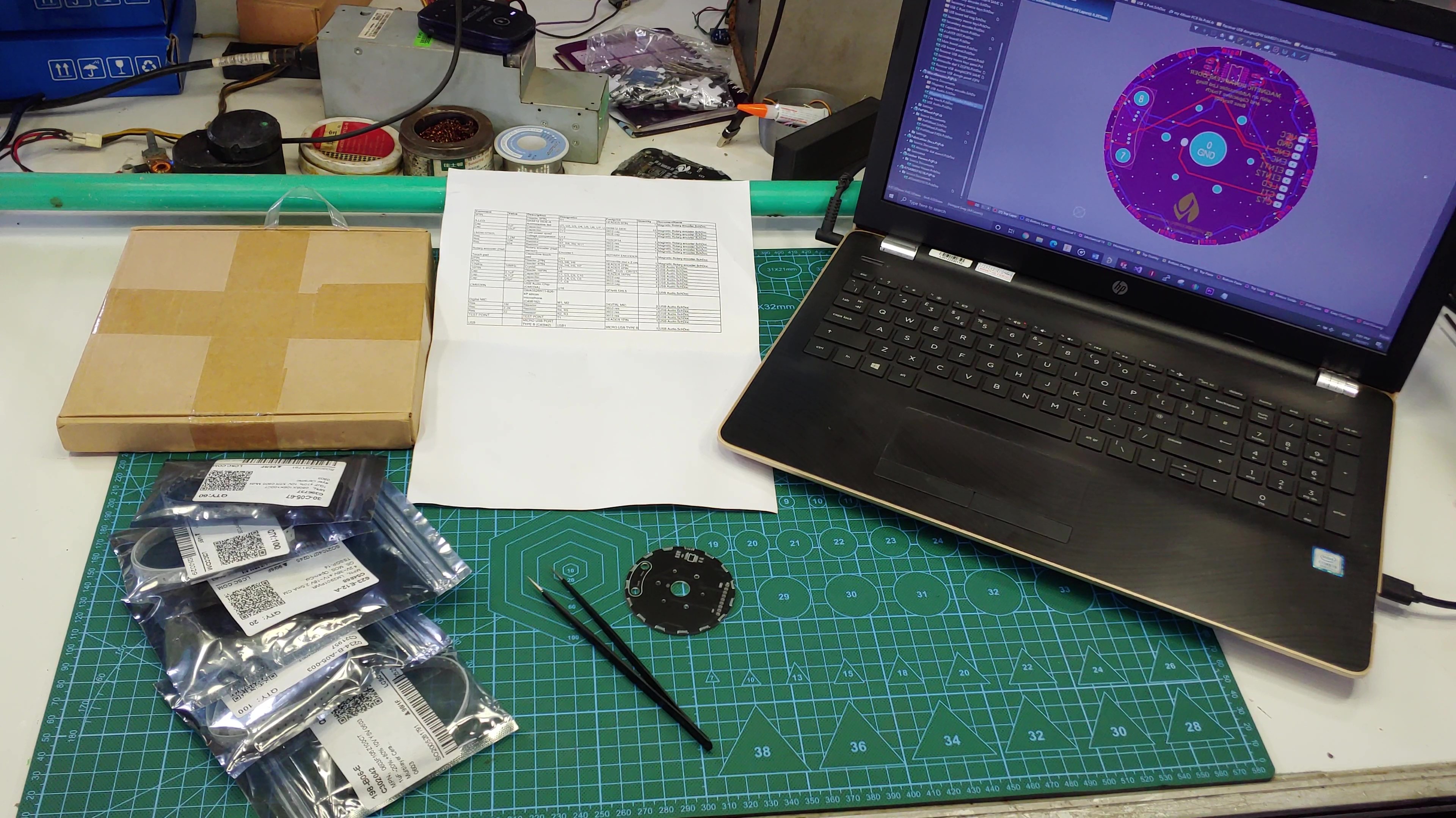
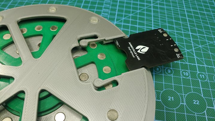
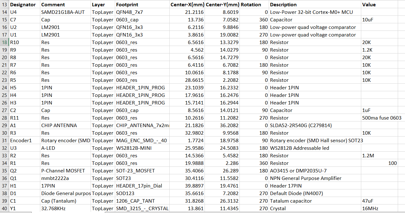
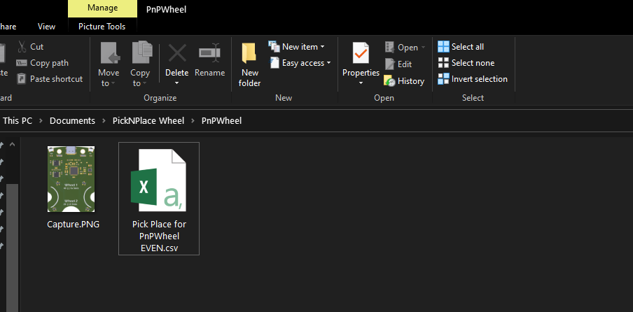
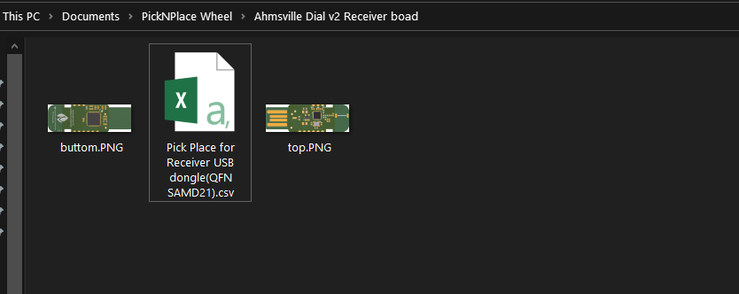
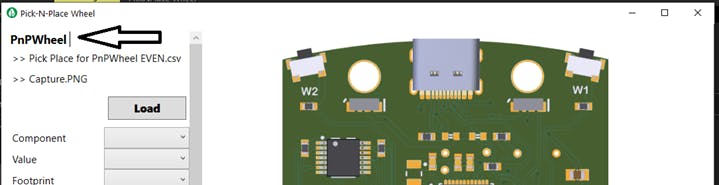
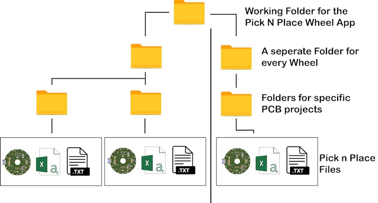
If you have ever hand assembled a PCB, the setup shown in the picture will look familiar to you, to populate a PCB, I would normally have all the components on the table, along with the pre-pasted PCB and a spreadsheet for the board I want to populate, this spreadsheet will usually contain important information like component value, footprint, designator and any other information that’ll enable me to accurately place the components. I would often also have my laptop close by so I can confirm the position on the board where specific components should be placed. With this process I usually avoid any placement errors, but the process can hardly be called efficient, especially if I have to assemble multiple PCB’s…so, my goal for the Pick-N-Place Wheel project is to combine all the elements associated with manual PCB assembly to form a system that is as seamless and as efficient as possible.

20210724_121701_3_gif_002.gif

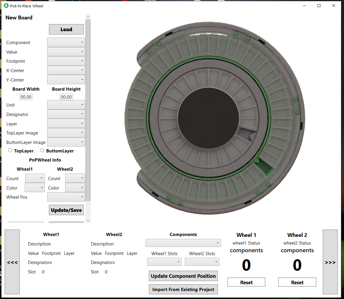
The Pick-N-Place Wheel is not just a 3D printed device, it’s a combination of three main elements: The 3D printed wheel itself which is the hardware, the rotary encoding and slot indexing; the electronics, and the control software in the form of a desktop application. The Pick-N-Place Wheel will not function as its intended without these three elements.

THE WHEEL

20210730_014053_Custom_3_gif.gif

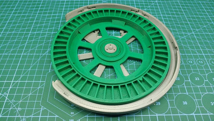
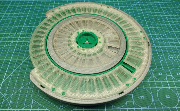
The wheel’s function is primarily to hold your components in indexed slots for when your populating a PCB, but it also doubles as the permanent storage for those components, thanks to the built in twist locking mechanism.

20210724_121701_2_Segment_0_gif.gif


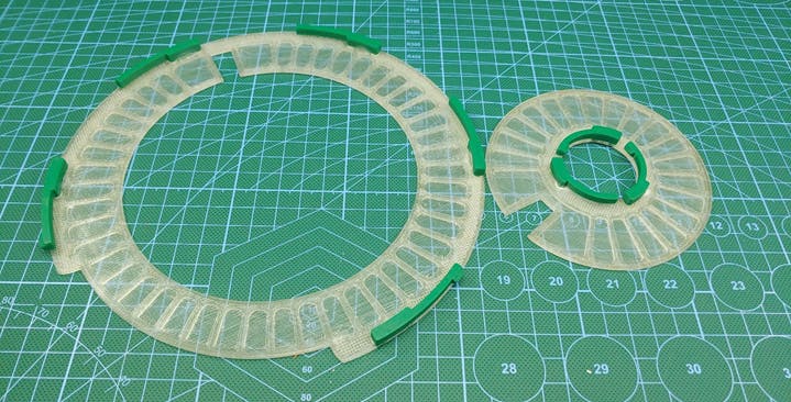
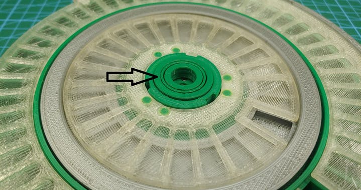
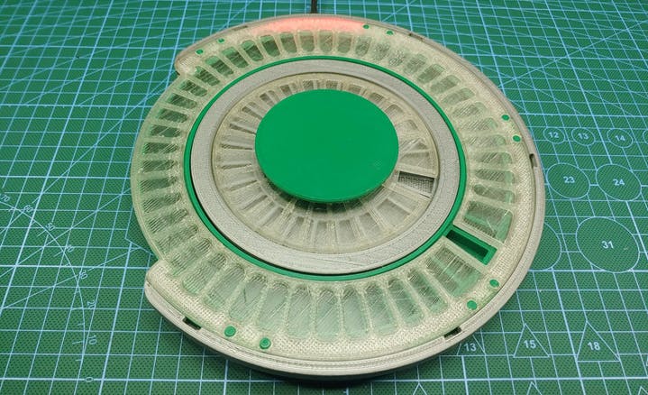
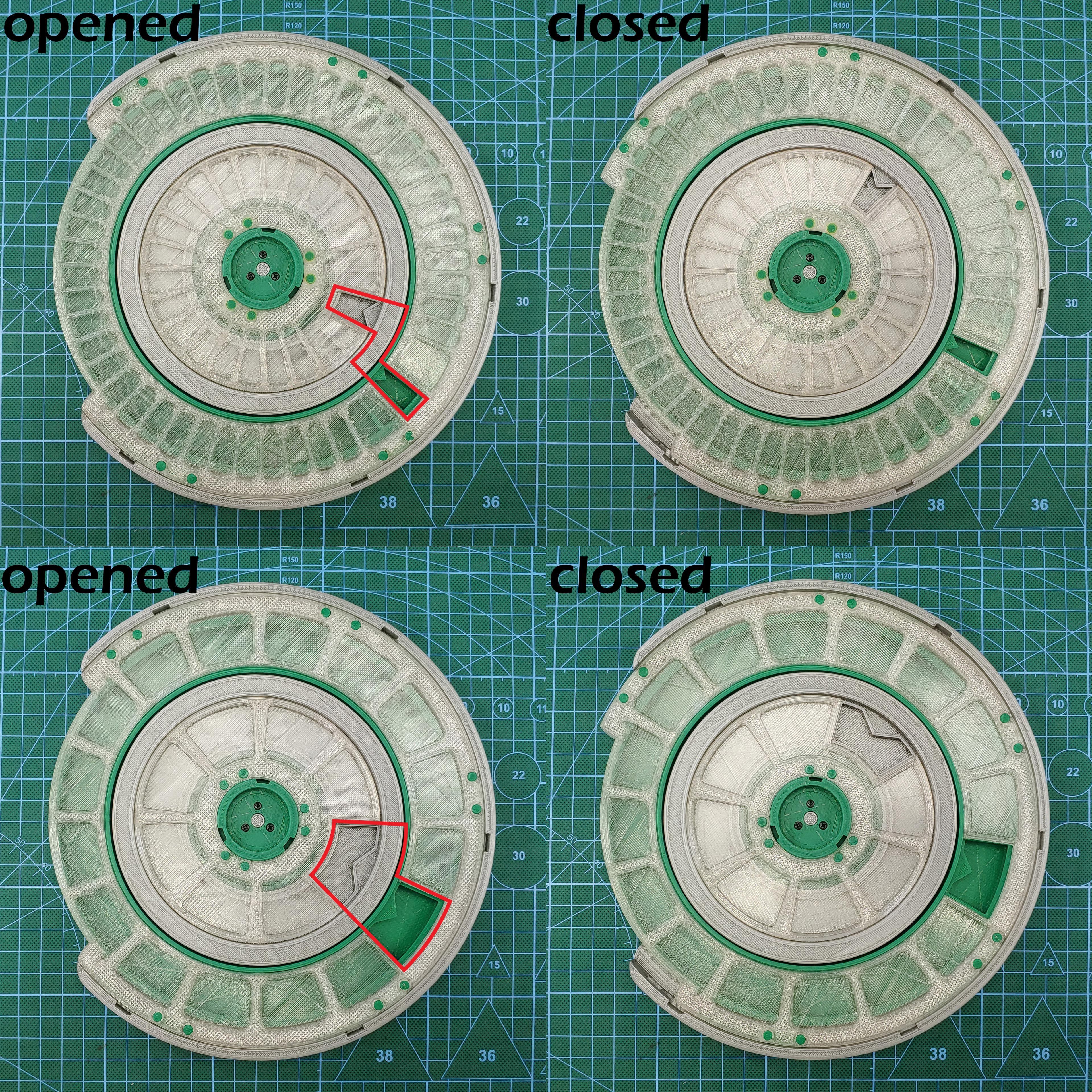
The wheel’s transparent top cover has a few flexible 3d printed tabs glued to it, this tabs fit into matching slots on the wheel, so that when you turn the top cover in one direction it creates a 1mm separation from the wheel (opened state), allowing the wheels to rotate freely during board population, and when the wheel needs to be stored away, the cover can be turned in the other direction which lowers it back down unto the wheel (closed state), sealing the components in their slots and preventing them from falling out or falling into another component’s slot. So instead of keeping components in the anti-static bags that they came in, the Pick-N-Place Wheel can be used to index and store them.

The Wheels of the Pick-N-Place Wheel

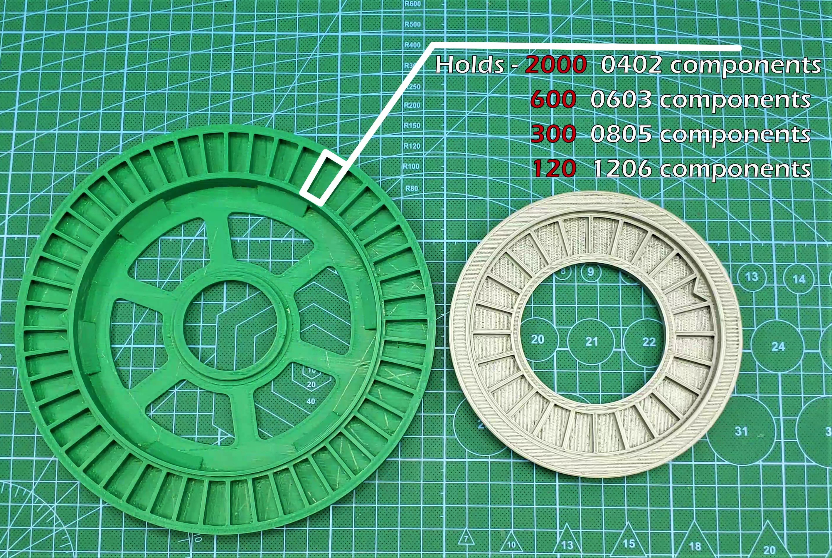
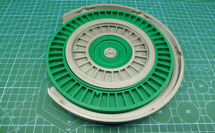
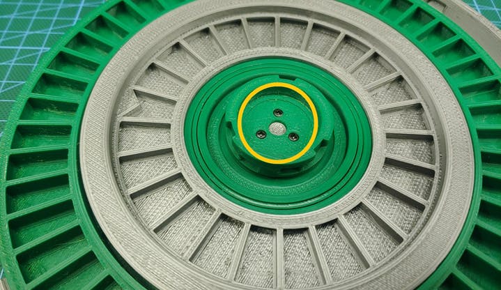
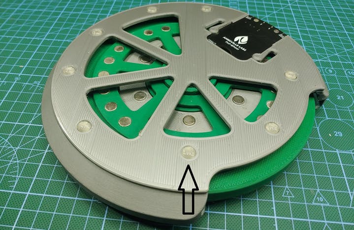
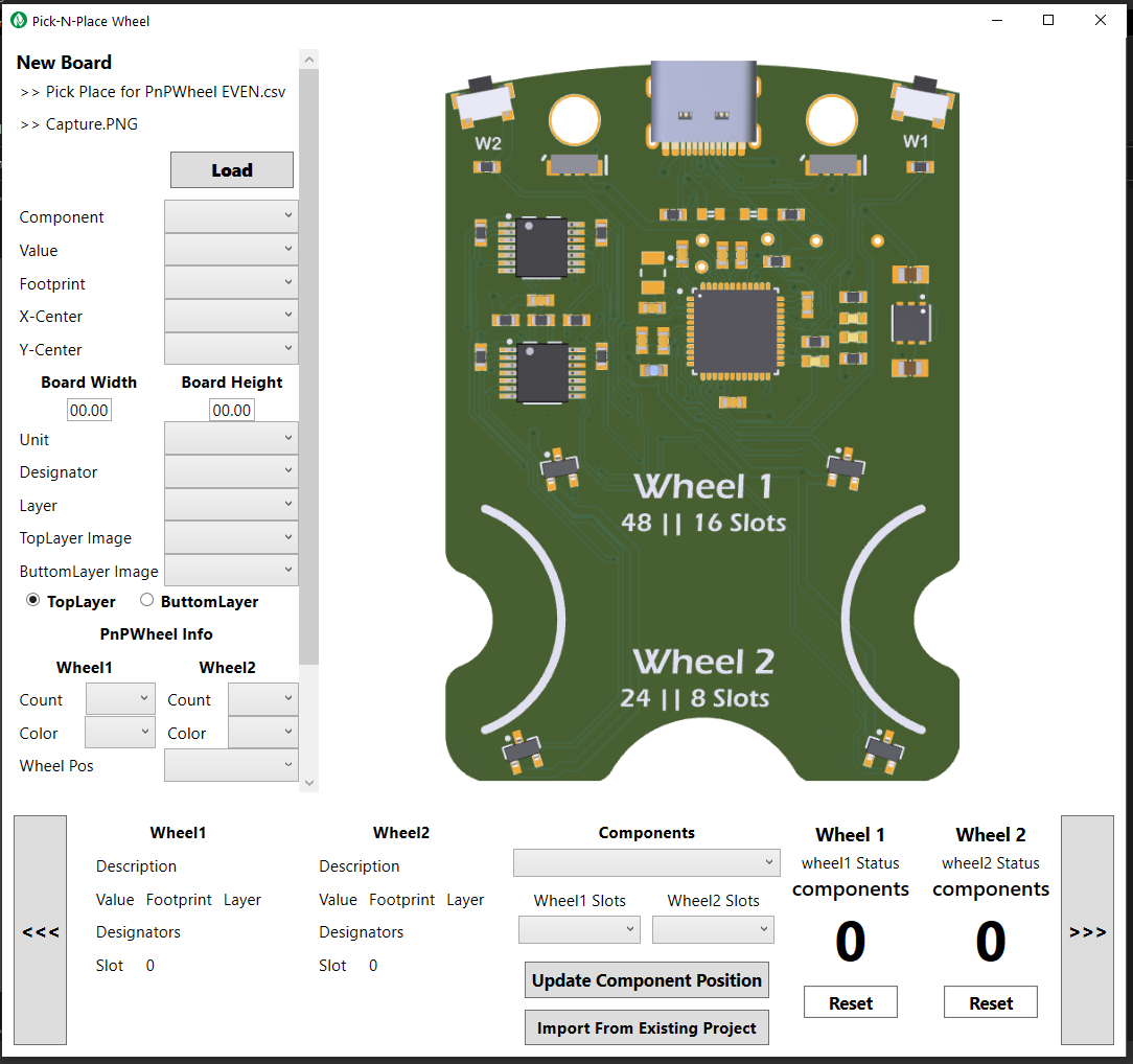
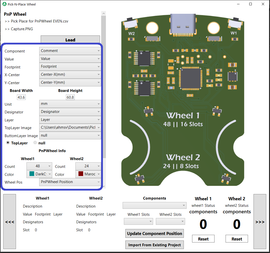
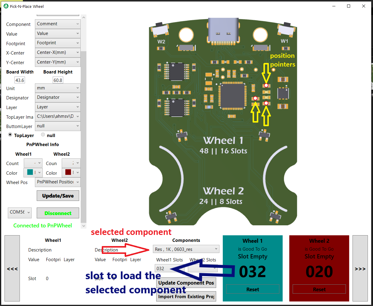
The Wheel is designed to hold two separately encoded wheels, one large outer wheel identified as wheel 1, and one smaller inner wheel identified as wheel 2. The image above shows the typical capacity of the wheel’s slots, each wheel has two versions, wheel 1 has a 48 and a 16 slot version, and wheel 2 has a 24 and a 8 slot version, this wheels can be combined in multiple ways to suit various types of PCB projects, the wheels with the higher slot counts are designed to hold a lot of small SMD components, while the wheels with the bigger slots are designed to hold bigger parts, like usb ports, leds, power inductors or connectors.

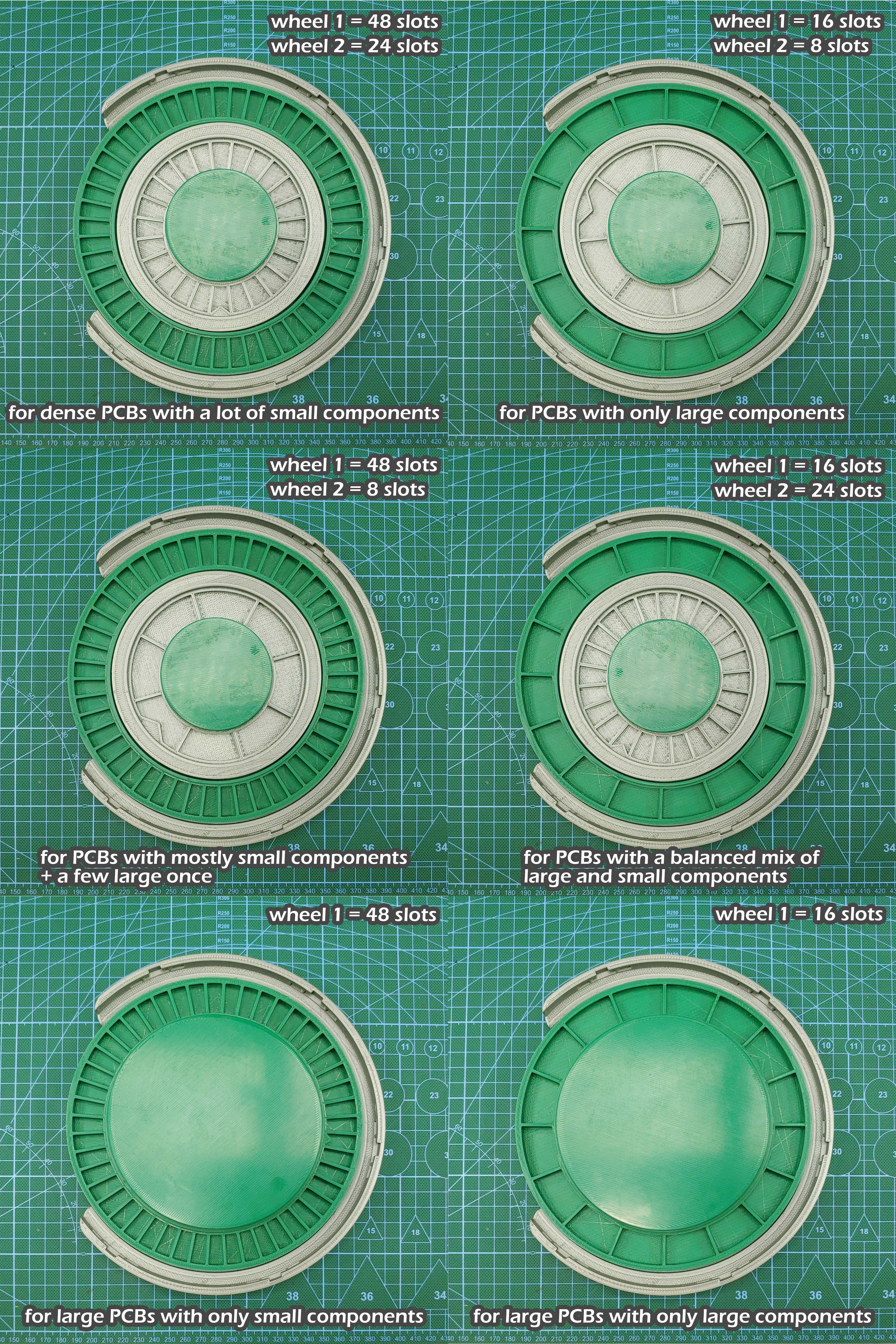
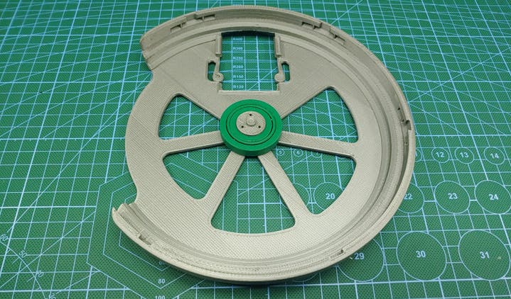
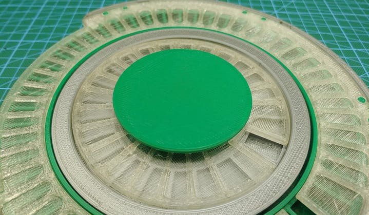
The placing surface where you’ll place the board you want to populate also has two versions to accommodate different board sizes. The image below shows all the possible configurations of the Pick-N-Place Wheel and their intended project types.

THE ELECTRONICS

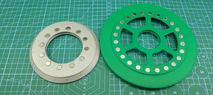
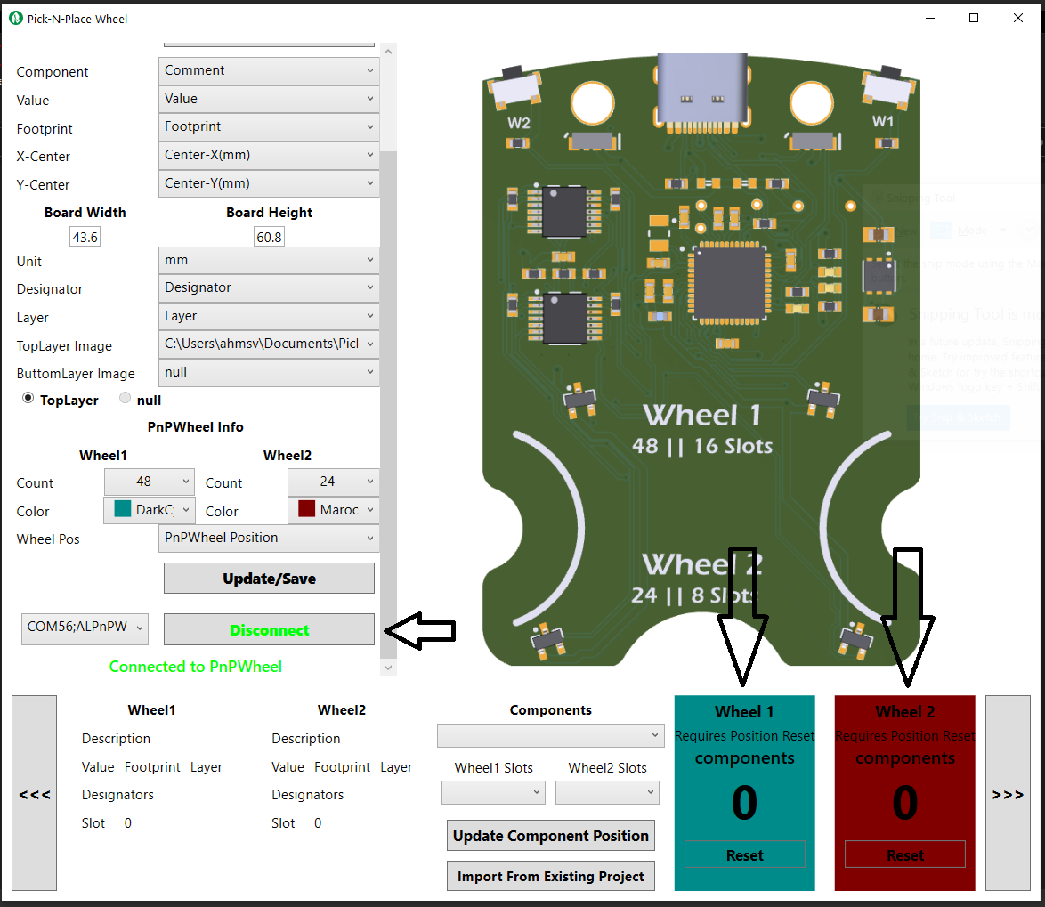
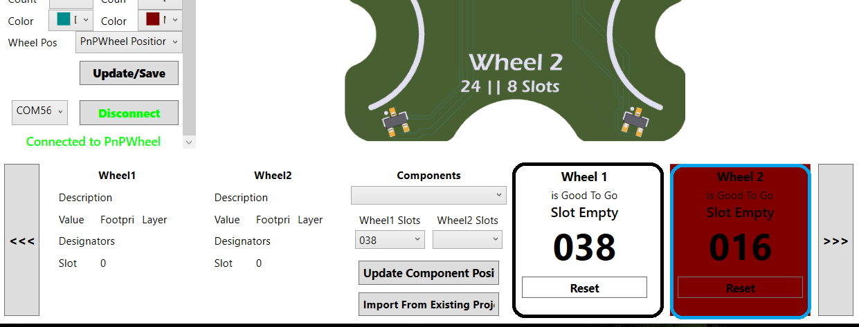
The Pick-N-Place Wheel is built around wheel encoding and indexing which is facilitated by the electronics.

20210730_014053_Custom_2_gif.gif


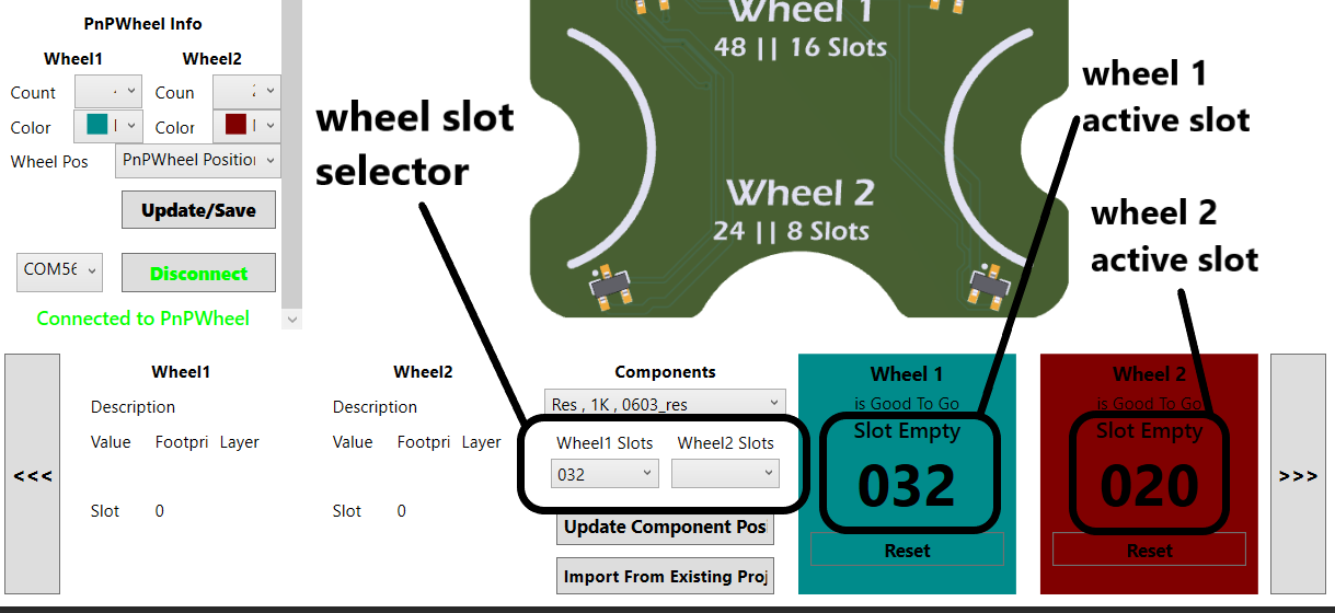
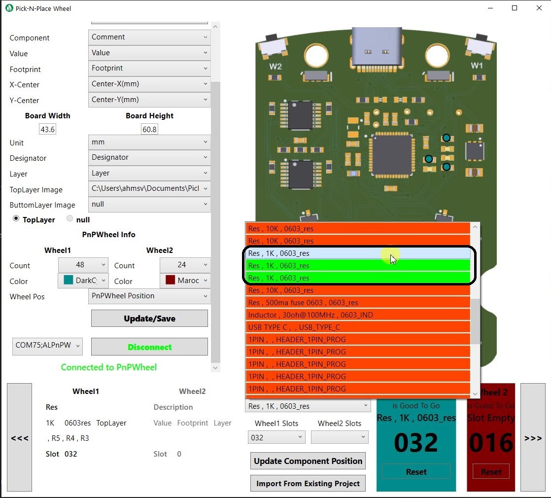
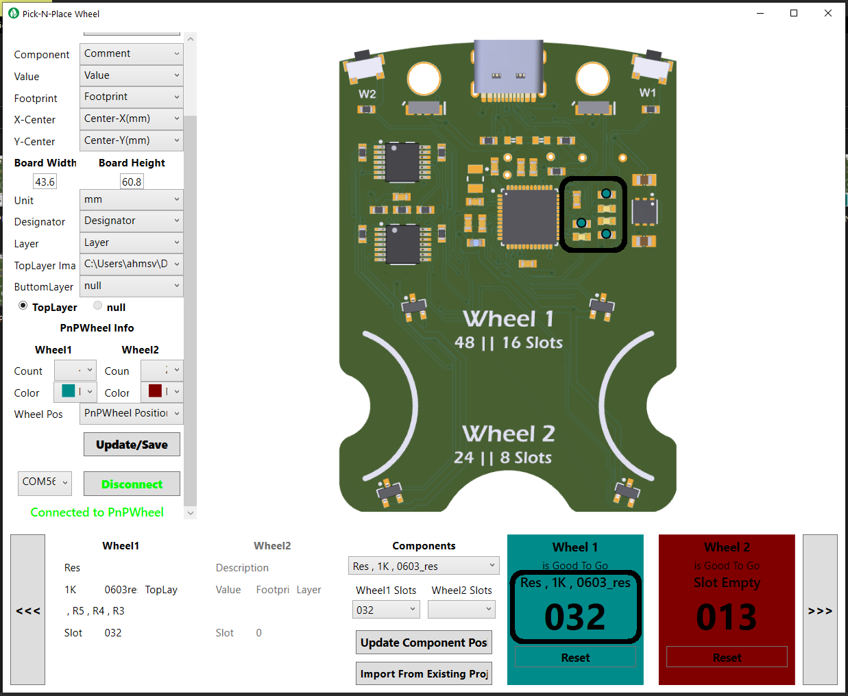
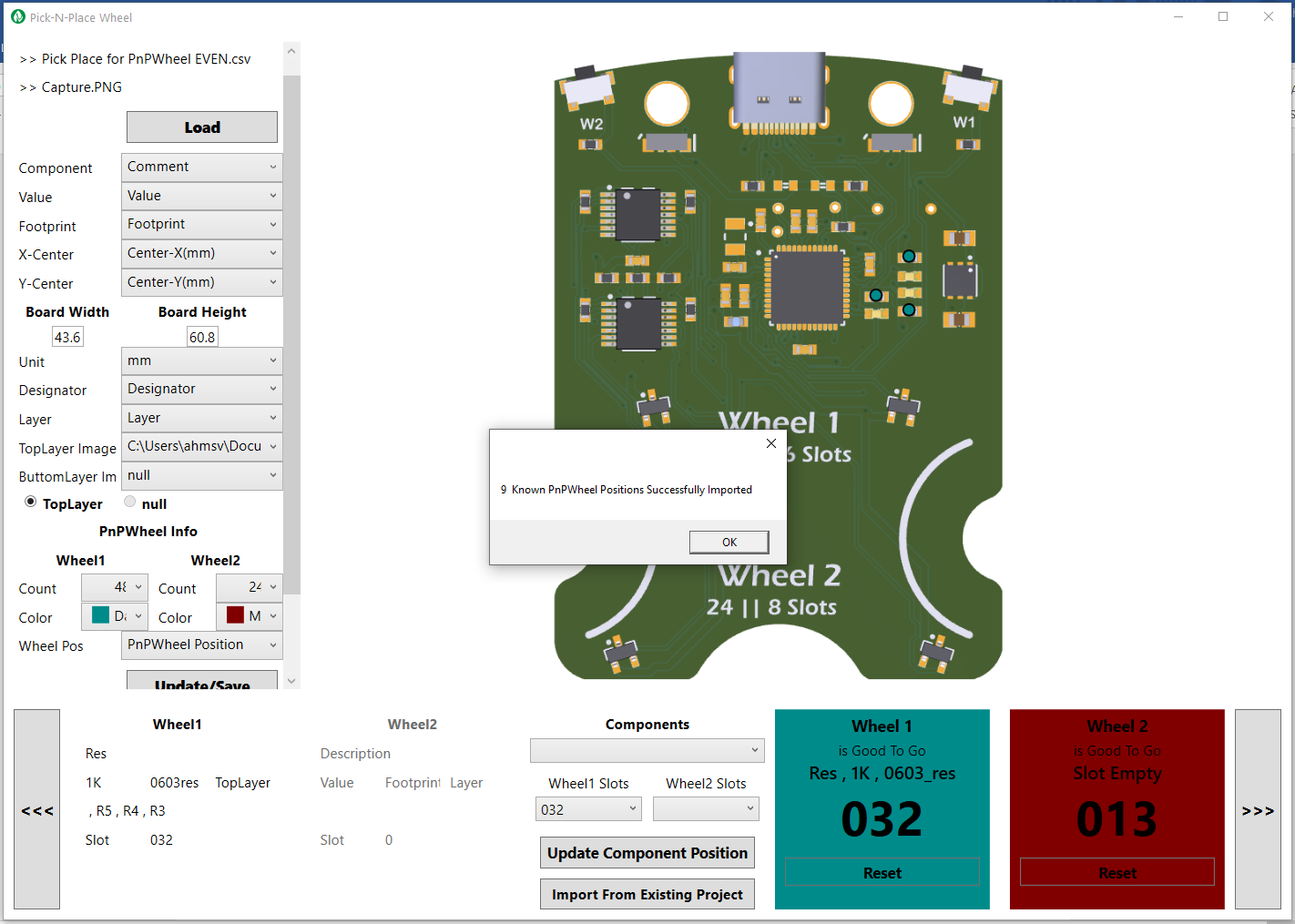
Each slot on the wheel has an index, this index is used to identify and place the...

Read more »

Standard Tesselated Geometry - 1.96 MB - 08/22/2021 at 23:38

Download

Standard Tesselated Geometry - 2.25 MB - 08/22/2021 at 23:38

Download

Standard Tesselated Geometry - 14.73 MB - 08/22/2021 at 23:37

Download

Standard Tesselated Geometry - 2.00 MB - 08/22/2021 at 23:35

Download

Standard Tesselated Geometry - 17.40 MB - 08/22/2021 at 23:35

Download

View all 28 files

  • 1 × Pick-N-Place Wheel Board This makes rotary encoding and slot indexing possible on the wheel https://www.tindie.com/products/24720/
  • 1 × 6810 Ball Bearing Capacitors / Film
  • 1 × 16004 Ball Bearing
  • 1 × 16001 Ball Bearing
  • 1 × 50x 8mm x 1.5mm disk Neodymium magnets

View all 8 components

  • 1
    Step 1

    Setting up and Using the Wheel

    In order to use the Pick-N-Place Wheel, you'll need to go through the first time setup process, this process involves:

    • 3D printing and Assembling the wheel to suite your desired PCB project.
    • Generating the required Files for the App.
    • Loading and Registering the components into the Wheel's slots.

    Assembling the Wheel

    Step 1: Choose your desired wheel configuration.

    Step 2: 3D print the required wheels for your chosen configuration, as well as all the other required parts.

    Step 3: install the magnets on the wheels in an alternating pole configuration.

    image.png

    Step 4: Glue on the locking tabs to the transparent top cover for wheel 1 and wheel 2.

    image.png

    Step 5: Install the 16004 ball bearing, followed by wheel 1.

    image.png

    image.png

    Step 6: Install the 6810 ball bearing to wheel 1, followed by wheel 2.

    image.png

    Step 7: Attach the placing surface bearing holder to the wheel, and secure it with 3 m2 screws.

    image.png

    Step 8: Attach the transparent top covers to the wheels, twist clockwise to lock them in the opened state or counterclockwise to lock them in the closed state.

    image.png

    Step 9: Install the 16001 ball bearing, followed by the placing surface.

    image.png

    You may also glue on a mat of some sorts to the placing surface, i use a 1mm silicone mat, this keeps the PCBs from sliding of the placing surface.

    image.png

    Step 10: Install the Pick-N-Place Wheel board to the base of the wheel, simply push it into its slot until it clicks into place.

    image.png

    Step 10: Attach the rubber base pads.

    image.png

    Congratulations!!! , its a Pick-N-Place Wheel.

    image.png

    Generating the required files

    The Pick-N-Place Wheel requires two files to operate:

    1. The pick and place csv file for your PCB.

    2. A top view Image of the PCB.

    Generating the pick and place csv file

    For every PCB you design, there is an associated pick and place file that can be generated, this can be done from the PCB design software. This pick and place file must be a dot(.) separated .csv file and it should contain the following columns:

    1. Component Name

    2. Component Value

    3. Component Footprint

    4. Component Designator

    5. Component Layer

    6. X-position (board origin at the bottom left corner)

    7. Y-position (board origin at the bottom left corner)

    A typical pick and place csv will look like this.

    Generating the Board Image.

    Like the pick and place file, most PCB design software will give you a 3d view of your board design, from which an image can be extracted, the image doesn’t have to come from the 3d view though, any image that gives you a good enough sense of where components are placed on the board will suffice.

    Your PCB should have its origin at the bottom left corner of the board, and the generated image needs to be in the same aspect ratio as your board, for example, if your board size is 20mm by 40mm the image size can be 10px by 20px, 50px by 100px or 2000px by 4000px, all this sizes are acceptable because they have the same aspect ratio as the board size, so a 100px by 500px image will not work for the 20mm by 40mm board.

    vbxfx.PNG

    The image also needs to be cropped to the edges of the board as shown in the sample image bellow.

    If your PCB has components on the bottom side, make sure to also generate an image for the bottom side of your board.

    sDasdad.PNG
    Board image.PNG

    Preparing the Generated Files

    After generating the .csv file and the board image, you’ll need to copy both files into a new folder, this will be the working folder that will be used by the Pick-N-Place Wheel App for the specific PCB project, the folder should contain only one csv and one image, for a PCB that only has components on the top side, one csv and two images for a PCB with components on the top and bottom sides.

    Sample folder for a traditional PCB with components on the top side only
    Sample folder for a PCB with components on both sides

    The folder containing the csv and image should then be copied into the “PickNPlace Wheel” folder which can be found inside the Documents folder, this folder is automatically created when you download and install the App from the github repository, the folder should hold all of your pick and place PCB projects, if you don’t see this folder in your documents folder, launch the App and then close it, the folder should show up.

    Using the App for The First Time

    Once all the required files have been copied to their appropriate folders, the next step is setting up the wheel and the app for your first board assembly.

    First your going to want to launch the application.

    image.png

    The Pick-N-Place Wheel Application interface

    Once the app opens up, click on the Load button, this will open up a dialog box, asking you to choose a project file.

    Navigate to the folder containing the csv and image and select any of them.

    After selecting the file, you will notice the image on the app change to the picture of your board, indicating that the required files have being successfully loaded.

    You’ll also notice that the file names are listed on the top right corner of the app.

    You can name the project (optional), by simply double clicking on New Board, and then typing in your desired project name.

    image.png

    The next step is setting the columns from your csv file to their appropriate comboboxes in the app.

    1. Component box should be set to the column that has the names of the components.

    2. Value box should be set to the column that has the values of the components.

    3. Footprint box should be set to the column that has the footprints of the components.

    4. X-Center box should be set to the column that has the x position of the component.

    5. Y-Center box should be set to the column that has the y position of the component.

    6. The board width and height should be set to the width and height of the PCB (the PCB design software will tell you this values).

    7. The unit should also be set accordingly

    8. Designator box should be set to the column that has the designators of the components.

    9. Layer box should be set to the column that has the layer of the components.

    10. TopLayer image should be set to the location of your generated board Image.

    11. BottomLayerimage should be set to the location of the generated Image for the bottom layer of your board (set to null if your board does not have components on the bottom layer).

    Under PnP wheel info, your going to want to set the slot count for your specific Pick-N-Place Wheel, so if you assembled your wheel with 48 slots for wheel1(bigger wheel) and 24 slots for wheel2(smaller wheel), you should set wheel 1 count to 48 and wheel 2 count to 24. All combinations are supported, so you could have wheel1 = 48 slots & wheel2 = 8 slots, wheel1 = 16 slots & wheel2 = 24 slots or wheel1 = 16 slots & wheel2 = 8 slots. Just make sure you set the slot counts in the app accordingly.

    You should also set distinct color identifiers for the wheels, this makes it easy to tell which wheel the displayed information is coming from.

    The last box named Wheel pos should be set to PnPWheel Position.

    After completing the selections, click on Update/Save button, this will allow you to save all your selections into a text file, so that the next time you load the project, all your selections are remembered. You should also remember to always save after making any modifications to the selections.

    Loading Components into The Wheel Slots

    After the initial setup process described above, the final step before you can start populating your PCB is Loading components into the wheel and updating the pick and place csv with the corresponding slot indexes, this is a very straight forward process, and it only need to be done Once.

    There are two ways to load the components and their slot indexes:

    1. Physical Loading Process – if you are using the wheel for the very first time, you will need to go through the steps described below for the physical loading process, this process allows you to fill the wheel with the components required for your board while also allowing you to update the positions (slot indexes) that specific components are loaded into.

    2. Import Loading Process – if you have already done the physical loading process once and you have already setup the Pick-N-Place Wheel for a different PCB and you’ll like to use the same wheel to populate a new PCB, probably because the boards use the same sets of components. In that case you don’t have to make a different Pick-N-Place Wheel, you can simply import the “components position information” form the csv for the previous PCB. What this essentially means is that if your PCB projects often use the same sets of components, you can use one Pick-N-Place Wheel to assemble them all.

    Physical Loading Process

    First, you’re going to want to connect your Pick-N-Place Wheel to your computer via a USB cable, after which you can then click on the connect button on the app. On successful connection, you’ll notice the status box for wheel 1 and wheel 2 blinking, indicating that your wheels “require position reset”.

    Before resetting the wheel, make sure the top covers and their slot openings are in the opened state, resetting the wheel in the closed state will produce erroneous indexing. The images below shows the wheels in their respective opened and closed states.

    To reset the wheels to the start position (slot index 1), simply rotate both wheels until the slot with an arrow head is exposed, once the wheels are in the start positions, click on the Reset button for both wheel 1 and wheel 2, this will set the wheel positions in the Pick-N-Place Wheel to “1” and the status box should also stop blinking.

    After the reset process, you’ll notice that the wheel index updates on the app as you rotate the wheels.

    Its also a good idea to double check that the start positions on the wheel is set properly, by simply rotating the wheels around the slot with the arrow head, the index of this slot on the app should always be “1”. The leds on the wheel will also shine blue whenever this slot comes around.

    At this point you may now begin loading components into the slots.

    Under the Components dropdown, you’ll find the list of all components that needs to be loaded for your PCB, the items in the list are highlighted in OrangeRed to indicate that the components don’t currently have a valid index in your wheel.

    Steps to Loading Components into the Pick-N-Place Wheel:

    1. Select a component from the Components dropdown, on selection, you’ll notice pointers on the board image indicating the positions on the board where the component is supposed to be placed.

    2. Rotate the wheel to any free slot (wheel 1 or 2), make sure the slot number shown in the wheel slot selector matches the corresponding slot number shown in the status box.

    3. Load the component into the appropriate slot with the help of the 3d printed funnel. For the example shown above, 1k 0603 resistors will be loaded into slot 32 of wheel 1.

    4. After loading the component into the wheel, click on “update component position” to register the position of the loaded component. If you then go under Components again, you’ll notice that every instance of the newly loaded component has changed to green, you’ll also notice that whenever you rotate the wheel to the slot where the component is loaded, the component details are shown in the appropriate wheel status box and the pointers on the board should also take on the color of the appropriate wheel.

    5. Repeat steps 1 - 4 for all the other components required by your PCB.

    Import Loading Process

    To load component positions from an existing project’s pick and place file, simply click on the “import form existing project” button and then locate and select the csv file that you’ll like to import the position information from.

    After the import process, you’ll notice that the components with known slot indexes will be updated and those components will be highlighted in green under the components list.

    After any of the two-loading process described above has been completed, you are now fully setup to populate your first PCB with the Pick-N-Place Wheel.

    Organizing your Pick-N-Place Wheel Projects

    If you assemble a lot of PCBs, you’ll most likely want to build more than one Pick-N-Place Wheel, so it’s really important to properly organize all the files used by the App.

    Asset 2@3x-100.jpg

    The image above shows the recommended way to organize the generated files, at the top level you have the main working folder for the App, this is where the App will first direct you to when you click on the Loadbutton, on the second level you have a folder for every Pick-N-Place Wheel that you build, its important to create a separate folder for every wheel since you’ll likely be loading the wheels with different sets of components. On the third level you have the main PCB project folders, this is where you’ll put the generated csv file and the board image, this folder should also hold the config.txt file for the specific PCB project, a new folder must be created for every board that you intend to populate using the Pick-N-Place Wheel.

    Final Notes:

    • The Pick-N-Place Wheel requires a 3D printer with at least a 220 x 220mm Bed size.
    • The Pick-N-Place Wheel App is currently only supported on Windows PCs, but a web version is currently in development, so it will eventually be accessible on any operating system.


View all instructions

Enjoy this project?

Share

Discussions

Darian Johnson wrote 10/15/2021 at 23:43 point

@Marcin Świerczek and @Ahmed Oyenuga -when you printed this (specifically the tabs) did you use PLA or PETG (or ABS)? I'm about to assemble mine tomorrow, and I didn't know if I should change my PLA-printed tabs to PETG.

  Are you sure? yes | no

Ahmed Oyenuga wrote 10/15/2021 at 23:54 point

Hi @Darian Johnson  i printed mine in PLA, because that's the material i like to work with, but there is no reason you cant use PETG.

  Are you sure? yes | no

Marcin Świerczek wrote 08/28/2021 at 05:48 point

Hi! I printed this project this week and I have some insights:

1. Why do you decided put 2 wheels on the common core? When I turn big wheel, the small wheel turns too. It's very frustrating for me. I'd like to be sure turn exactly this wheel which I want.

2. Are you thought about bigger versions of big wheel? 48+24 that's a bit too little for some projects. I wouldn't like to change all cells every project. 72+36 should be an option. I know, 3D printed has limited area, but CNC laser has a lot bigger :) It could be made of two plexiglass joined together. What do you think?

3. I think you need to work on tolerances for 3D printed parts. Wheel 24 cells is perfectly fitting to mount bearing, but I had to put some sticky tape on the core so that it doesn't rotate in the middle. It probably resulted from the fact that your bearing case it was printed, isn't it? I used metal bearings. 

4. I suppose a bit bad idea with used glue to pasting the lockers. It can definitely be designed better without the use of glue of any part of this project. 

For me the concept is very good, but it needs a few tweaks for perfectly and simple design. 

You still haven't shared PCB files or BOM for PCB, but the software is available, fun fact :) Which hall sensors did you use?

  Are you sure? yes | no

Ahmed Oyenuga wrote 09/09/2021 at 17:38 point

Hi Marcin

1. designing the wheel with a common core was a compromise to maximize the slot count, slot size and placing surface size, considering it was designed to be printed on a 200x200 mm bed. You should also know that there are wheel keys included with the 3d printable files, these keys allows you to lock any of the wheels during use. 

2. I am already developing a bigger version of the wheel for 300x300 bed sizes, and that will come with some size benefits which includes more slots for both wheels.

3. i usually design my parts with tolerances that i believe most people will be able to achieve on their varying machines, but if i get enough reports about the tolerance, i'll make sure to adjust it accordingly.

4. i guess i could use self tapping screws instead.

i might eventually share the PCB files, but that will probably be at a later time.. the hall sensors are 49E linear hall effect sensors.

Thanks a lot for taking the time to give a feed back on the project, it really helps me to improve the wheel.

  Are you sure? yes | no

Trailhead wrote 08/18/2021 at 18:53 point

Are the gerber files or schematic available for the boards?  I'd be happy to buy one but I would also like to assemble my own.  Love the design and docs so far.  Seon at Unexpected Maker graciously shared his source CAD files.  It would be nice if you did too.  The main wheels seem to require a lot of support material.  If I had the source files for those I'd make them modular so I could glue the pieces together and not require support.

  Are you sure? yes | no

Ahmed Oyenuga wrote 08/18/2021 at 20:05 point

Hi, i have added the CAD files to the GitHub repository, the schematic should also be added soon.

  Are you sure? yes | no

Trailhead wrote 08/18/2021 at 23:41 point

Thanks!  Will you be releasing the PCB gerbers at some point?  

  Are you sure? yes | no

Xasin wrote 08/16/2021 at 20:38 point

*Scrolls down all the way to the bottom, huffing*
WHEW, made it!! 

That is a LOT of quality documentation on this awesome project. Thank you so much for detailing the process, and wow, that PCB there is really neat too.

I wonder if a Bluetooth version, or maybe adding an ESP32 for WiFi, could make it a bit neater to use...

I'm also thinking of maybe making quickswap cartridges and all that sort of fun~

This is definitely something I will have to build myself, because... Well, we all know how nice it would be to properly store away capacitors etc.

  Are you sure? yes | no

Similar Projects

Does this project spark your interest?

Become a member to follow this project and never miss any updates