Close
0%
0%

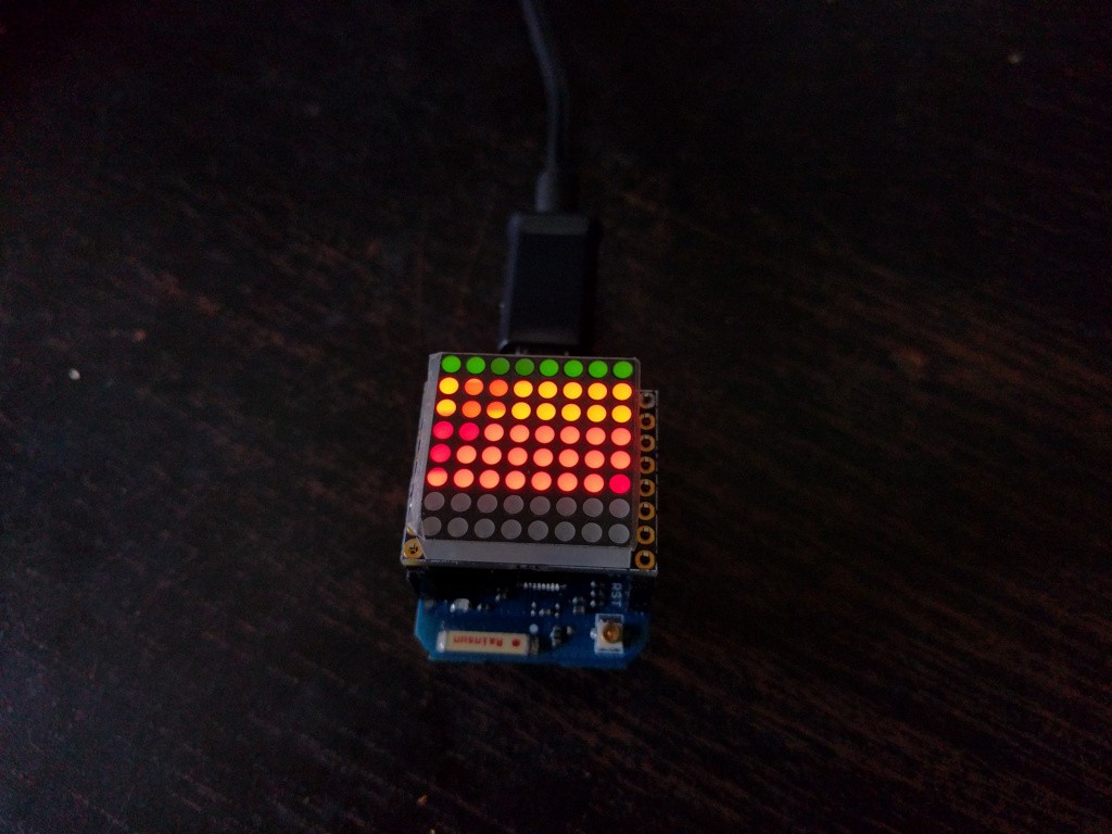
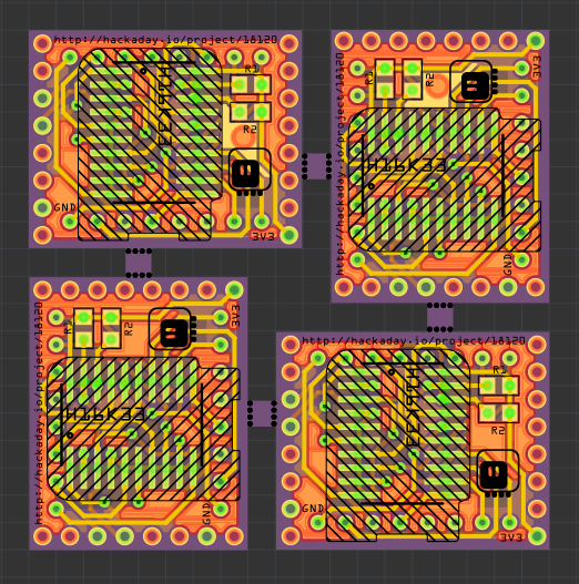
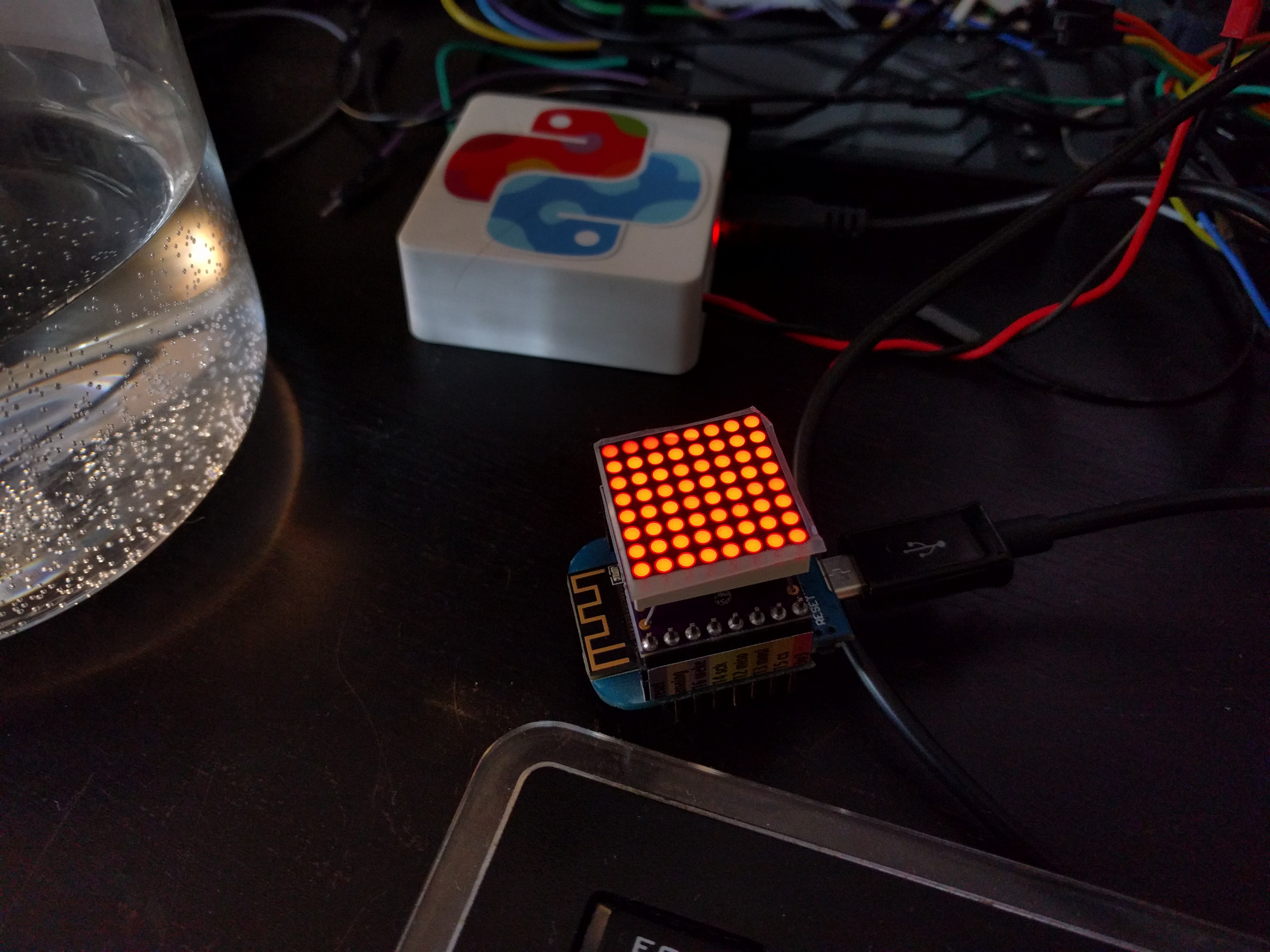
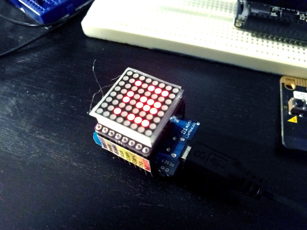
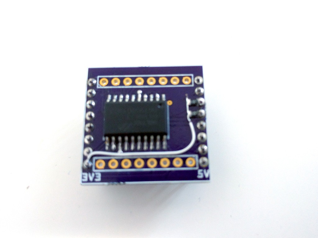
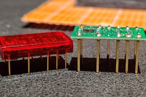
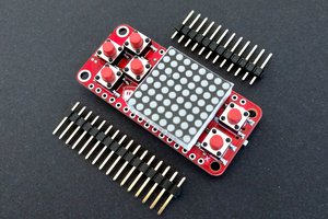
D1 Mini Matrix Shield

A shield for the D1 Mini ESP8266 board with HT16K33 chip and 8x8 mini LED matrix.

Similar projects worth following
Starting from
$5.00
deshipu has 296 orders / 19reviews
Ships from Switzerland

A shield for the D1 Mini ESP8266 board with HT16K33 chip and 8x8 mini LED matrix.

x-fritzing-fzz - 28.71 kB - 03/04/2017 at 20:27

Download

  • 1 × HT16K33 in a 20-pin package
  • 1 × 8x8 mini LED matrix (common anode)
  • 2 × 10kΩ 0805 SMD resistors
  • 2 × 8x1 pin 2.54mm pitch male headers
  • 1 × PCB

  • Competition

    deʃhipu05/28/2017 at 01:57 5 comments

    As they say, be careful what you are wishing for, you might get it. My main motivation for making all those D1 Mini shields and selling them is to make this functionality available -- first from my @Tindie shop, and then, hopefully, from Aliexpress and eBay, as it gets cloned and manufactured cheaply.

    Recently WeMos, the very company that makes the D1 Mini boards, has introduced a new product -- a 8x8 LED matrix shield similar to what I have been making here. Here's a link: https://www.aliexpress.com/store/product/Matrix-LED-Shield-V1-0-0-for-WEMOS-D1-mini/1331105_32812932291.html -- thanks to @davedarko for the tip!

    However, this is not a clone of my shields. It's a complete re-make of the idea, with a different chip on board, using different pins and protocol for communication, and not software compatible. As far as I can tell there are not libraries or code examples for it.

    I ordered one out of curiosity and will experiment with it, but for now let's see what I we can infer from the photos. The chip used is AIP1640, which seems to be a cheap clone of the TM1640 LED driver, produced by http://titanmec.com/. There seem to be no English datasheets for it, but there is one in Chinese available from http://titanmec.com/index.php/product/view/id/305/typeid/59.html

    This chip can drive up to 8x16 LEDs, so only half the outputs are used for driving the 8x8 matrix -- you could drive a double or bi-color matrix with it (like this one: https://www.aliexpress.com/item/8x8-LED-Red-Green-Dual-Color-Dot-Matrix-Display-Module-TM1640-for-Arduino/32476051733.html). The inputs are connected to D1 Mini's MOSI and SCK pins through transistors, because it's a 5V device. The protocol it uses for communication is a weird mix of SPI and I²C: you send serial data, but because there is no chip-select pin, you denote start of transmission with I2Ć-like start condition. There are no addresses, though -- the device basically owns the pins it is connected to all the time. The driver does support PWM, but you can only change the brightness of the whole matrix, and not individual pixels.

    There seems to be an Arduino library for the TM1638, that also supports TM1640, but it seems to be only for 7-segment displays. The library can be found here: https://github.com/rjbatista/tm1638-library

    Speaking of the TM1638, I can't understand why they didn't use that chip, or one of the other LED driver chips manufactured by Titanmec (they have quite an interesting offer, see http://titanmec.com/index.php/product/lists/typeid/59.html). For instance the TM1629 or TM1638 (http://titanmec.com/index.php/product/view/id/303/typeid/59.html, English datasheet at https://retrocip.cz/files/tm1638.pdf) -- it's smaller, supports 8x8 LEDs and uses a proper SPI protocol that plays nice with other devices. Or use the venerable HT16K33, which is well tested, has proper I2C and already has a lot of existing libraries. I suspect they got a really good deal on those clones...

    Perosnally, I find the TM1680 particularly interesting, as it should be capable of driving an RGB matrix with I2C: http://titanmec.com/index.php/product/view/id/393.html

    In the mean time, I will keep selling my own matrix shields on Tindie -- they can't compete with these price-wise, but I think they are much easier to use, at least for now.

  • Some Good News

    deʃhipu04/07/2017 at 08:27 0 comments

    Despite all the problems, I'm persevering. Today the common-cathode bi-color matrices arrived, and I was able to try them with the HT16K33:

    Of course, the pattern is pretty much random, because I still need to adjust the software for the pretty much random column and row assignment I made. But you can see the colors, and they are nice (the slight variations of color on the photo are due to the camera sensor interfering with the PWM).


  • The Curse Strikes Again

    deʃhipu04/06/2017 at 08:57 11 comments

    Remember when I wrote that I ran out of mistakes to make in this project? Was I ever wrong. The PCBs just came from DirtyPCBs:

    That's not the kind of panelization that I expected... Of course I immediately downloaded back the zip file with gerbers and checked it:

    Yup, that's what I sent them to make (unless they do some processing to it). Of course I didn't notice a problem, because the preview at DirtyPCBs is broken since they switched to the new website, and doesn't show the board outline.

    Now I have a few days of dremeling before me.

  • Deluxe Matrix

    deʃhipu04/05/2017 at 10:54 0 comments

    I now created a new project for trying out the new chips: #D1 Mini Matrix Deluxe Shield

  • Different Chips

    deʃhipu03/27/2017 at 22:14 0 comments

    While ordering the different colors for the mini 8x8 LED matrices, I couldn't help but notice the bi-color and RGB matrices in the same size. The RGB one would be a bit difficult to route for me on a two-sided PCB, but I decided to give the bi-color one a try and ordered it. It should be super-easy to route, because the row pins are actually in order on both sides, and in the middle are the common column pins. The only problem is that I would need to use the 28-pin HT16K33 chip, and it would need to sit across the middle column -- but with good flat wire cutters that seemed doable.

    Recently the matrices arrived, and also the PCB from OSHPark that I ordered to test the bi-color matrix:

    As you can see, I didn't care about the order of rows and columns, and just routed them in random order -- assuming I can fix that in software later on. Unfortunately, the matrix didn't work. A closer inspection revealed that I got the common-anode matrix, whereas the HT16K33 can only handle the common cathode ones. Bummer. I ordered the correct, common-cathode matrices then.

    But now I have a bunch of matrices I can't drive easily, and this feeling that I should really do something with them. I looked for a chip that could handle them, but in vain. I posted a question to the stack, and updated it with what I found. And then, @Jeremy Gilbert suggested a family of chips that I forgot about.

    You see, there are those charlieplexed LED FeatherWings that Adafruit has, with a very cool IS31FL3731 chip. I even wrote a MicroPython library for driving them once! But I didn't realize that there is a whole family of those chips, and they are not only for charlieplexed displays, also for regular matrices. And they are much more modern than the venerable HT16K33, and have cool features, like the ability to set the brightness of every pixel individually, built-in blinking and animations, and even changing the brightness according to audio input!

    So I decided to try and also make a couple of shields with those. We will see how well that works, for a start I ordered a board for the simplest IS31FL3728 chip:

    It will probably be a bit tricky to solder, being in a QFN package, but nothing that I didn't manage before. I will keep you updated.

  • Great Success

    deʃhipu03/15/2017 at 10:12 0 comments

    The last version of the PCBs arrived, and lo and behold: they work perfectly fine! I even used the same chips and matrices that I brutally desoldered from the previous prototypes -- and they work fine too. That means I can make my order for the mass production!

    Well, for some definition of mass. I have panelized the design to fit 4 boards in are of 5x5cm, to maximize the yield. A single order of 10 boards should give me 40 boards -- and that's how many I plan to make for a start, ten of every color. I have ordered the chips and the matrices already, so the PCBs will be the last component to arrive.

  • Progress

    deʃhipu02/22/2017 at 13:01 0 comments

    A proper schematic helped -- the connections are now all correct. Of course I forgot to move the pins for the matrix closer together, so the pin spacing is wrong now...

    But I think that I finally ran out of mistakes to make. Ordered the fixed PCBs, and prepared a 4x panelized PCB fitting in 5x5cm, for a "production" order. I will, however, wait until the current version arrives and tests before I order those.

  • This Project is Cursed

    deʃhipu01/25/2017 at 18:46 0 comments

    The new, "fixed" boards arrived. Guess what. They don't work. Actually, they work, but only partially. Why? Because I mixed up the pins of he matrix, that's why. Here's the matrix filled completely:

    I think that what I need is a proper schematic, together with properly labeled headers, and time during the day to do the traces (instead of doing them at 2am). Otherwise it's just an exercise in futility.

  • Boards #5

    deʃhipu01/10/2017 at 15:51 1 comment

    The chain of stupid mistakes continues. The new boards arrived shortly before Christmas, but I didn't have more HT16K33 chips to test them. Today, after a month on the way, the chips finally arrived. Of course, because I put the chip on the bottom layer this time, I mirrored the footprint and all the pins are wrong. I soldered two boards before I realized (because I wanted to make sure it's not a faulty chip). When I realized it's the PCBs that are wrong, not the chips, I decided to recover them. I don't have a hot air gun at home, so I went for the hot-plate approach. First, I removed the plastic from the pin headers, and desoldered each pin. Then I turned on my electric kitchen stove, waited a bit until it became hot, placed a board chip-up on the plate, and pulled with tweezers on the chip. At some point it just came off. I repeated the same with the second board, and even got the SMD resistors back.

    Then it's back to the drawing board. I re-did all the connections the correct way, and ordered the boards again. See you in a few weeks when they arrive.

    This was really supposed to be a short and simple project...

  • Pullups

    deʃhipu12/14/2016 at 08:33 0 comments

    Just a quick confirmation. Yes, after adding the pullups, suddenly all of the shields are working.

View all 15 project logs

Enjoy this project?

Share

Discussions

davedarko wrote 11/10/2016 at 18:57 point

ahhh, the picture tricked me into thinking it's done already!

  Are you sure? yes | no

deʃhipu wrote 11/10/2016 at 19:20 point

No, that's just a mockup with a bare matrix, no PCB. The PCB will stick out about 2.54mm on each side...

  Are you sure? yes | no

Similar Projects

Does this project spark your interest?

Become a member to follow this project and never miss any updates