 Michael Laffin
Table of Contents - Log Files
Robot arm manufacturing details
Background
For those with upper extremity impairments that affect strength and reach, performing simple physical activities of daily life can prove to be insurmountable. Assistive robotic arms have been shown to be effective tools to increase user autonomy within these tasks and can significantly reduce caregiver intervention.[1]
User interfaces for commercial assistive robot arms vary between products, however most are centered around standard wheelchair joysticks or keypads. Such interfaces can lead to a significant bottleneck in user efficiency that is caused by the reality of controlling a high-dimensional robot arm with a low-dimensional "conventional" joystick. That is, without the use of additional intelligent control algorithms, auxiliary buttons and low DoF joysticks are used to switch between control modes to perform compound movements.
Such operation is simple however, small delays from switching joints can quickly accumulate into a significant amount of time for the user. The this project is an investigation into the viability of concurrent joint operation, opposed to consecutive operation of individual joints as seen in many current systems.
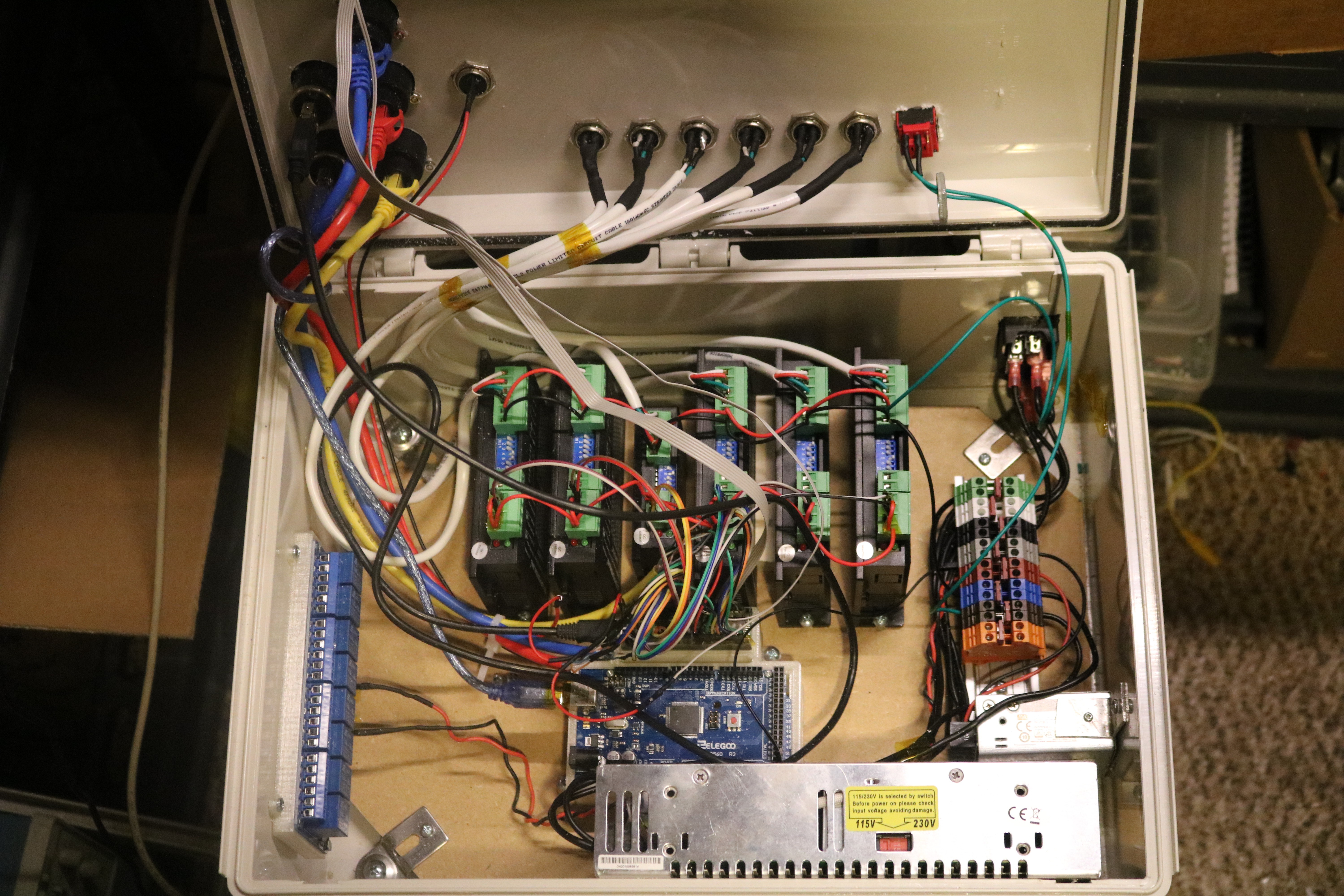
System Overview
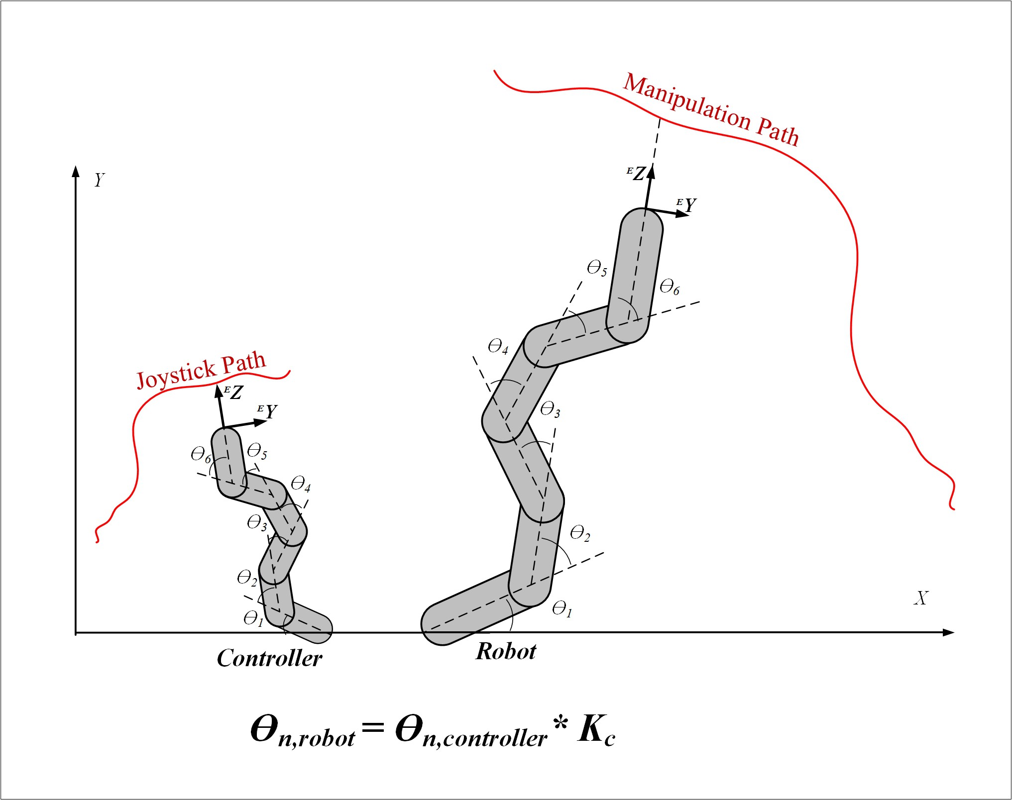
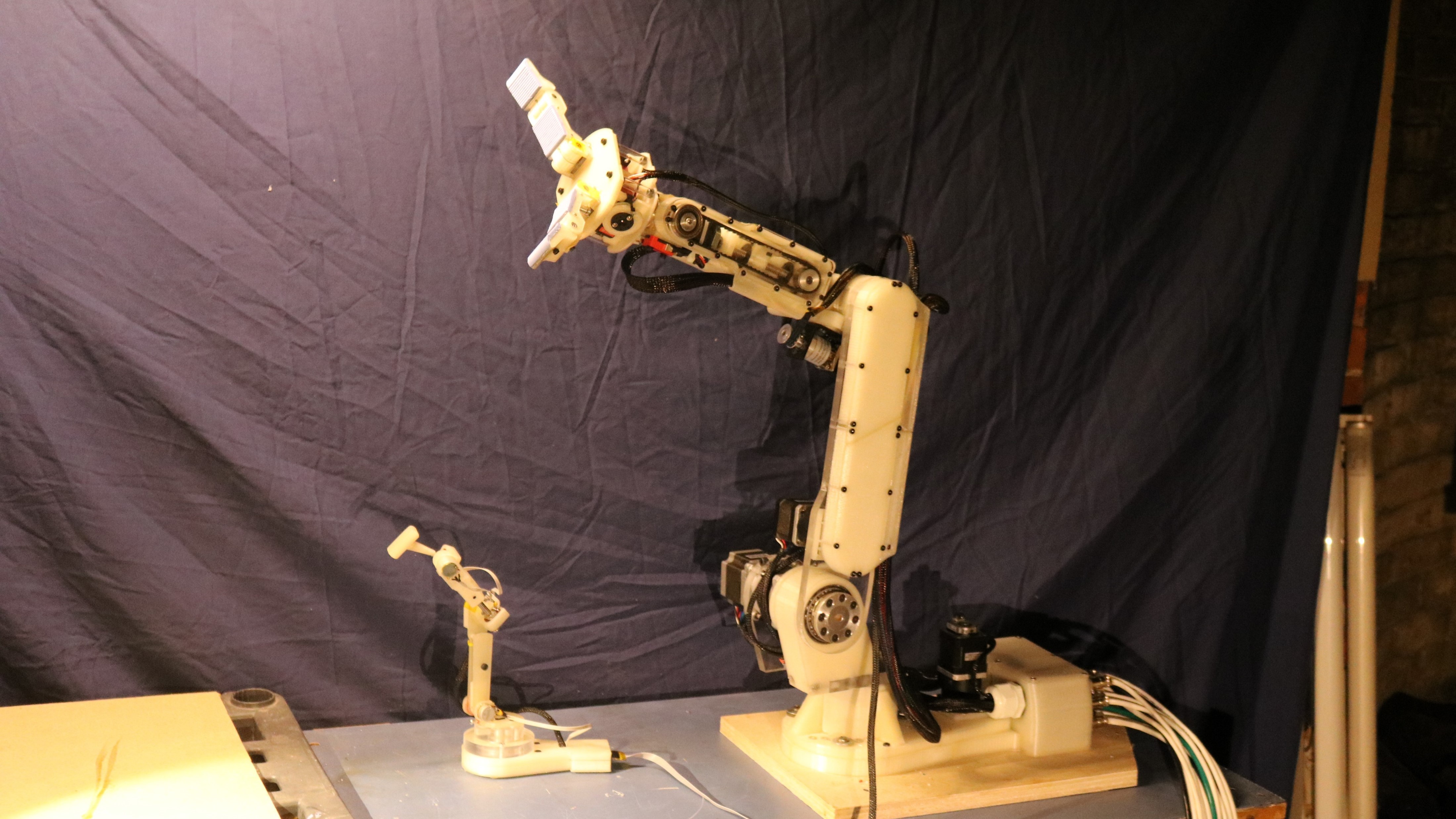
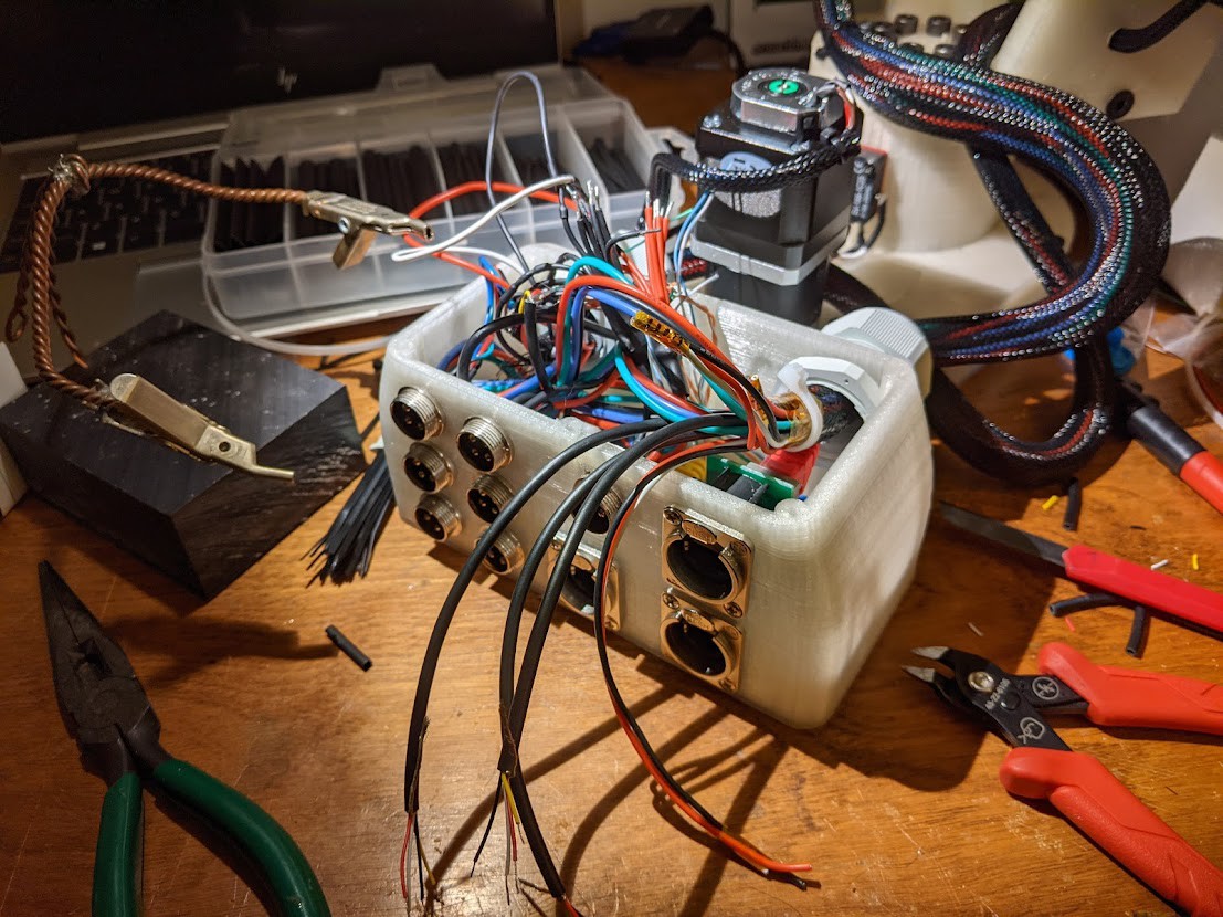
The proposed experimental system hardware consists of a robotic arm, a controller arm, and an electronics housing. The controller arm acts as a 6-dimensional joystick, and its pose can be manipulated to proportionally control the robot arm. Calibrating sensitivity of individual joints on the joystick to exploit the user's specific abilities can allow for an increased range of motion of the robot arm.
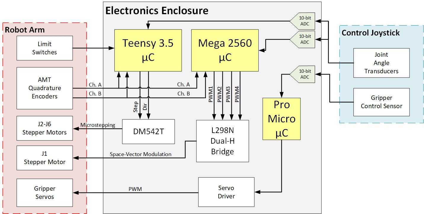
A functional diagram of the electrical system can be seen below.
The core assumption underlying the operation of this device is that the intended user possesses sufficient motor control to move the control joystick in at least several different directions. Not all six axis are required for operation, but the more used will allow for improved functionality in manipulation.
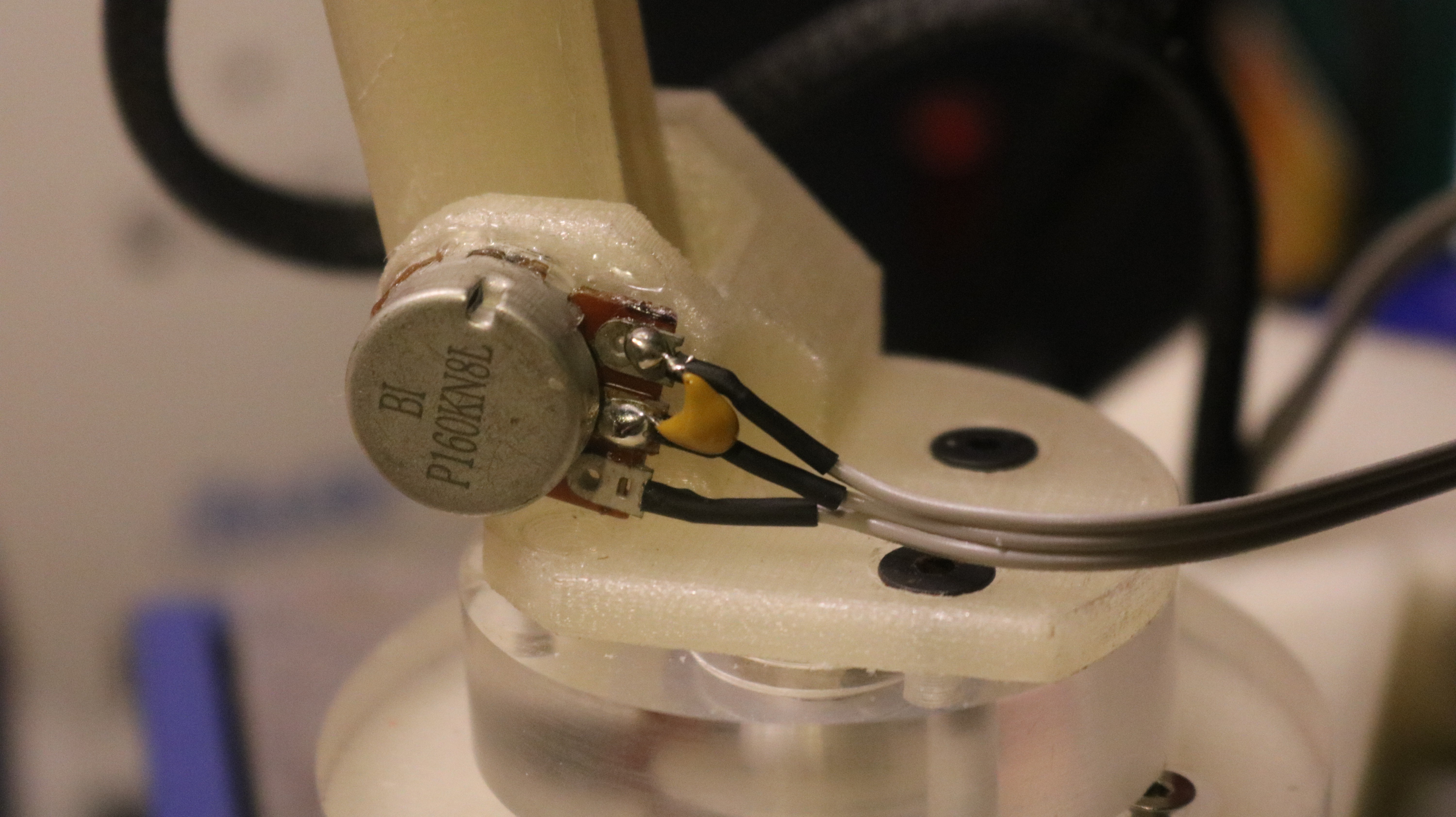
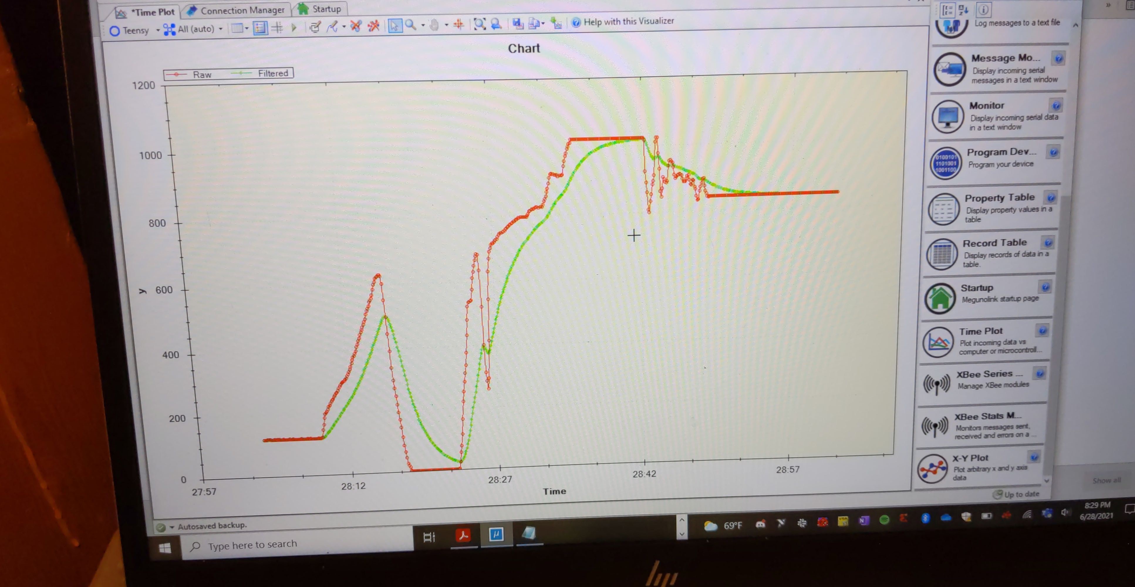
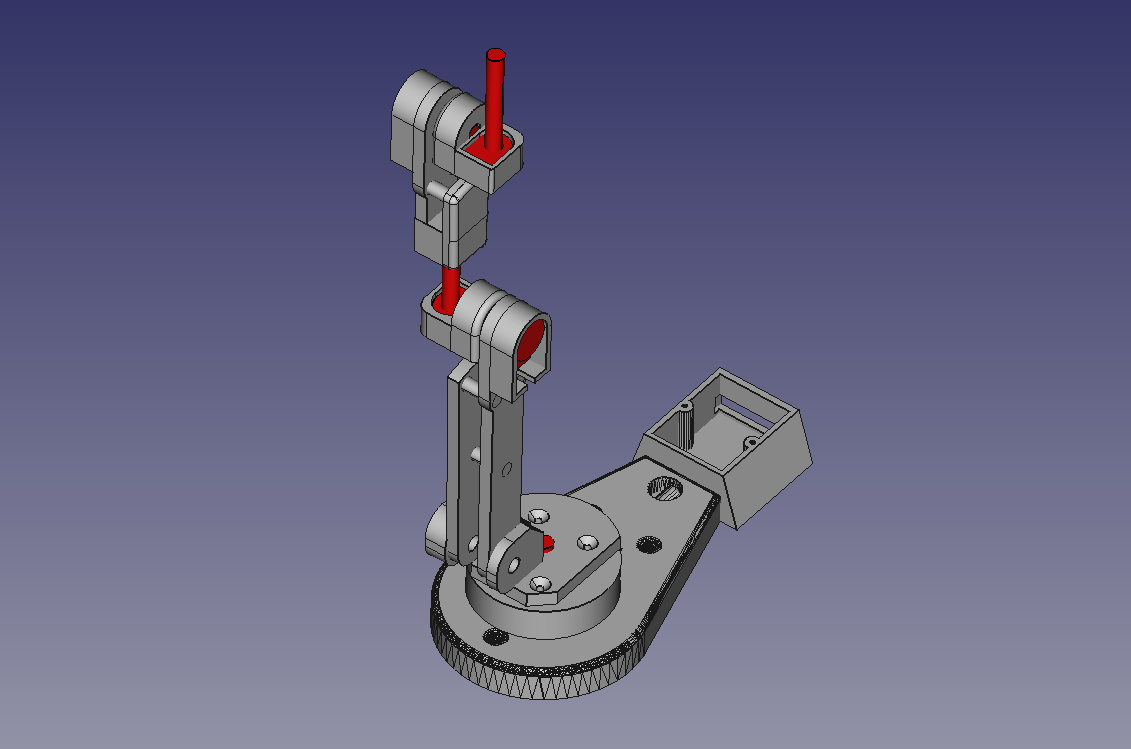
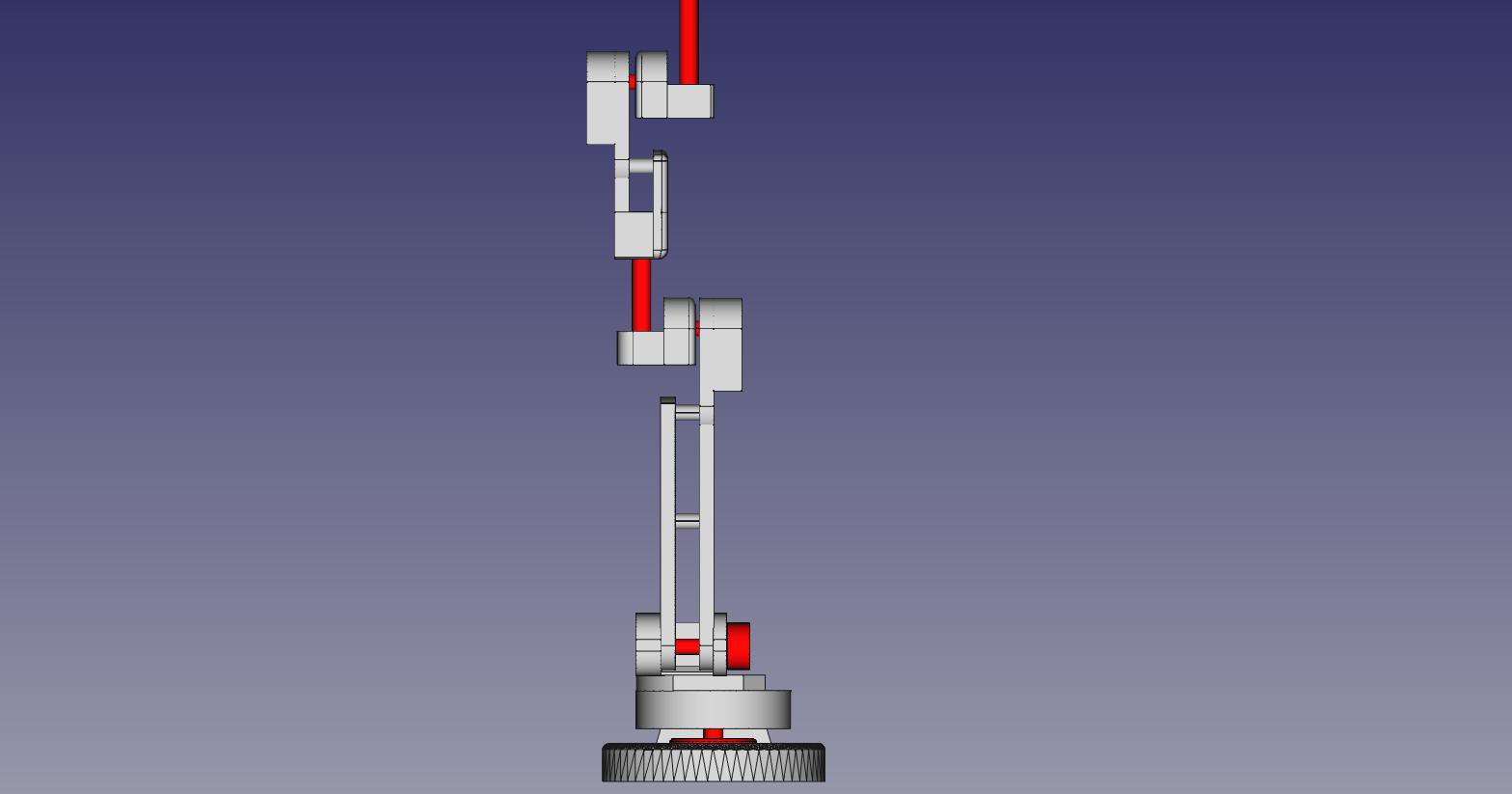
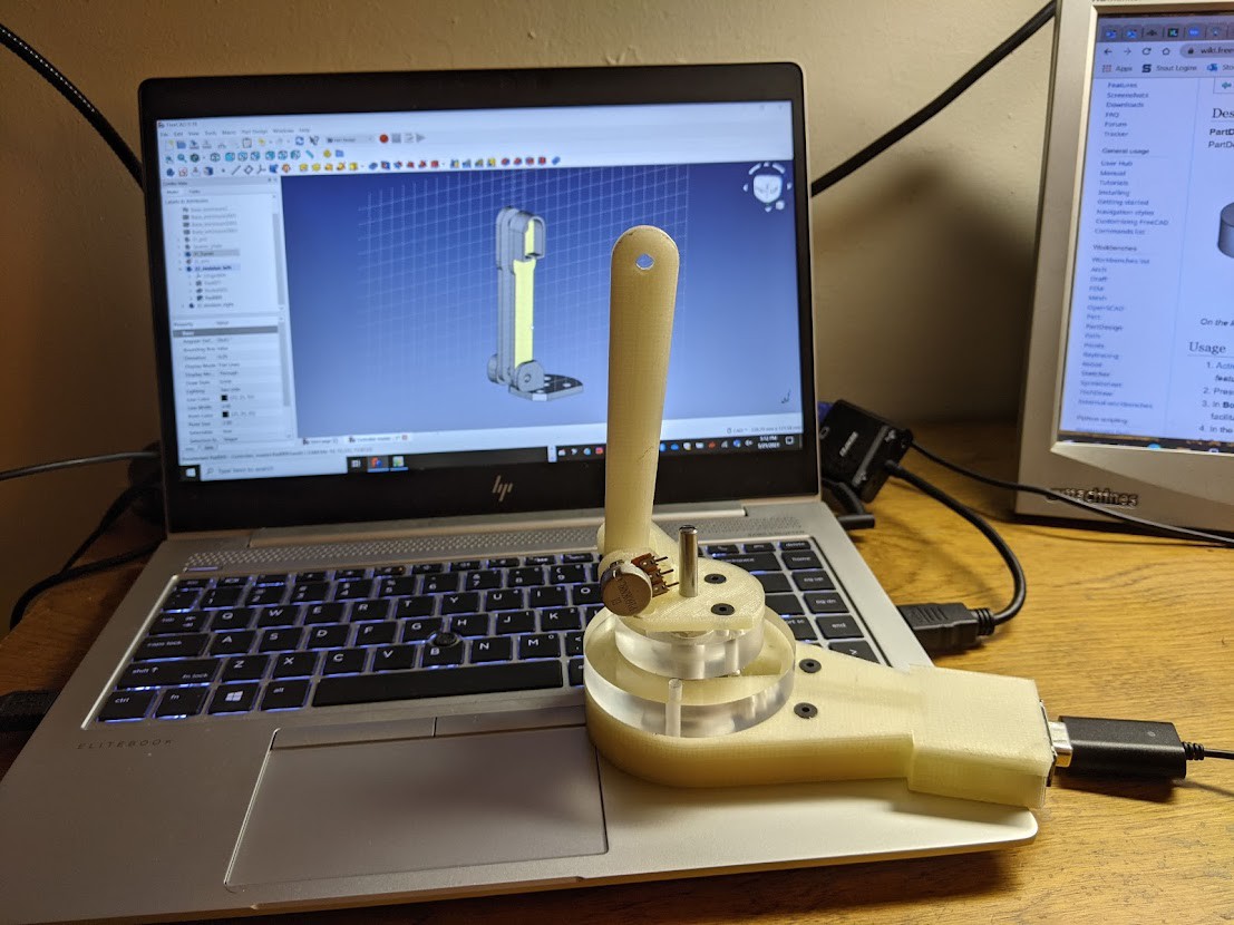
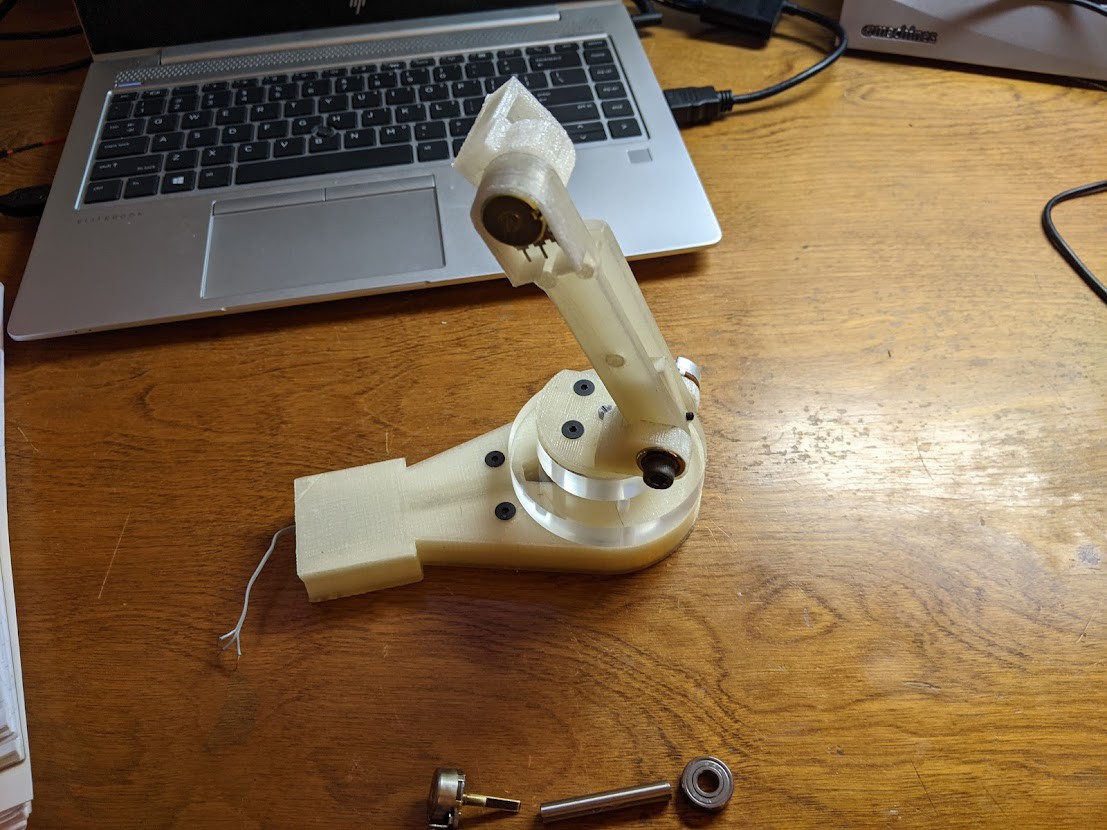
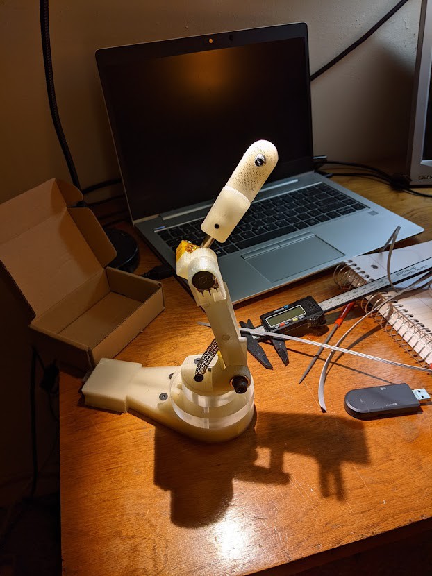
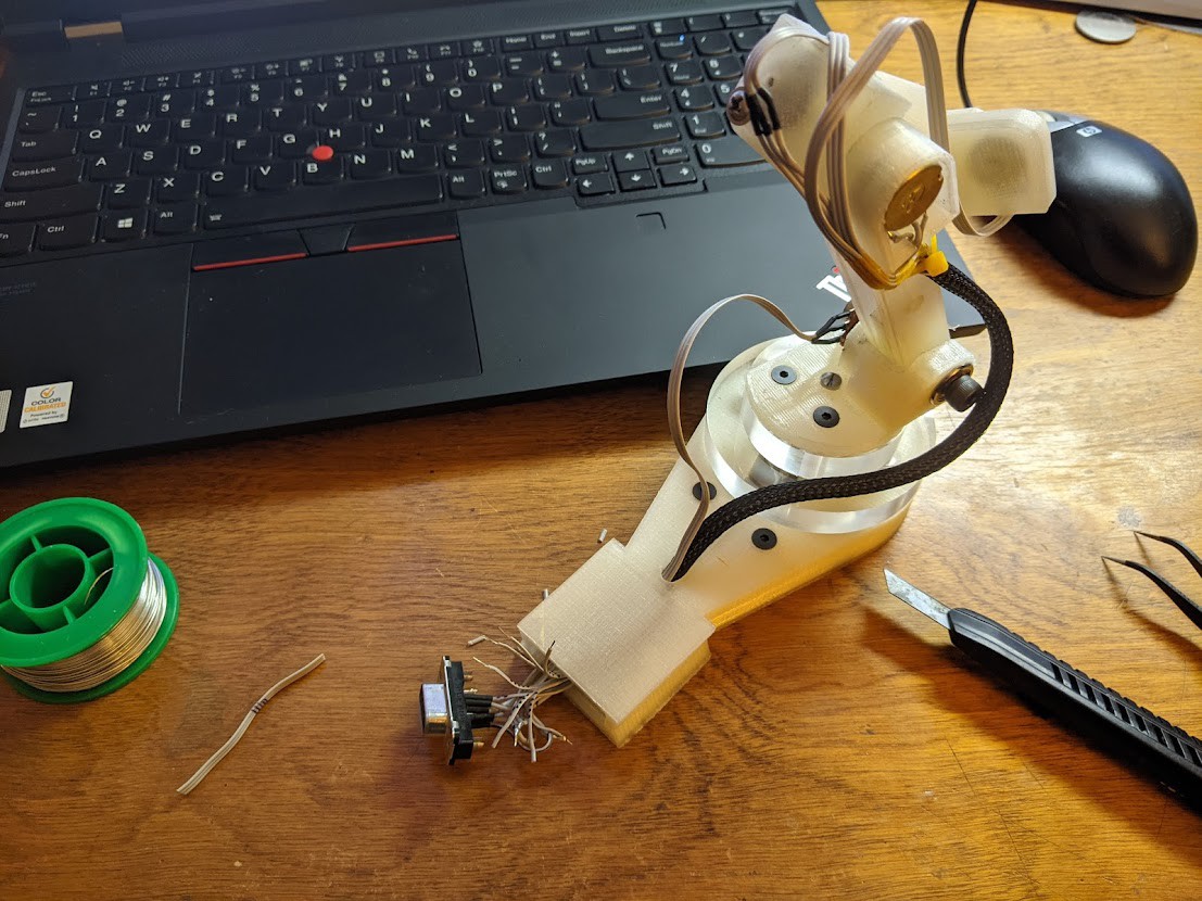
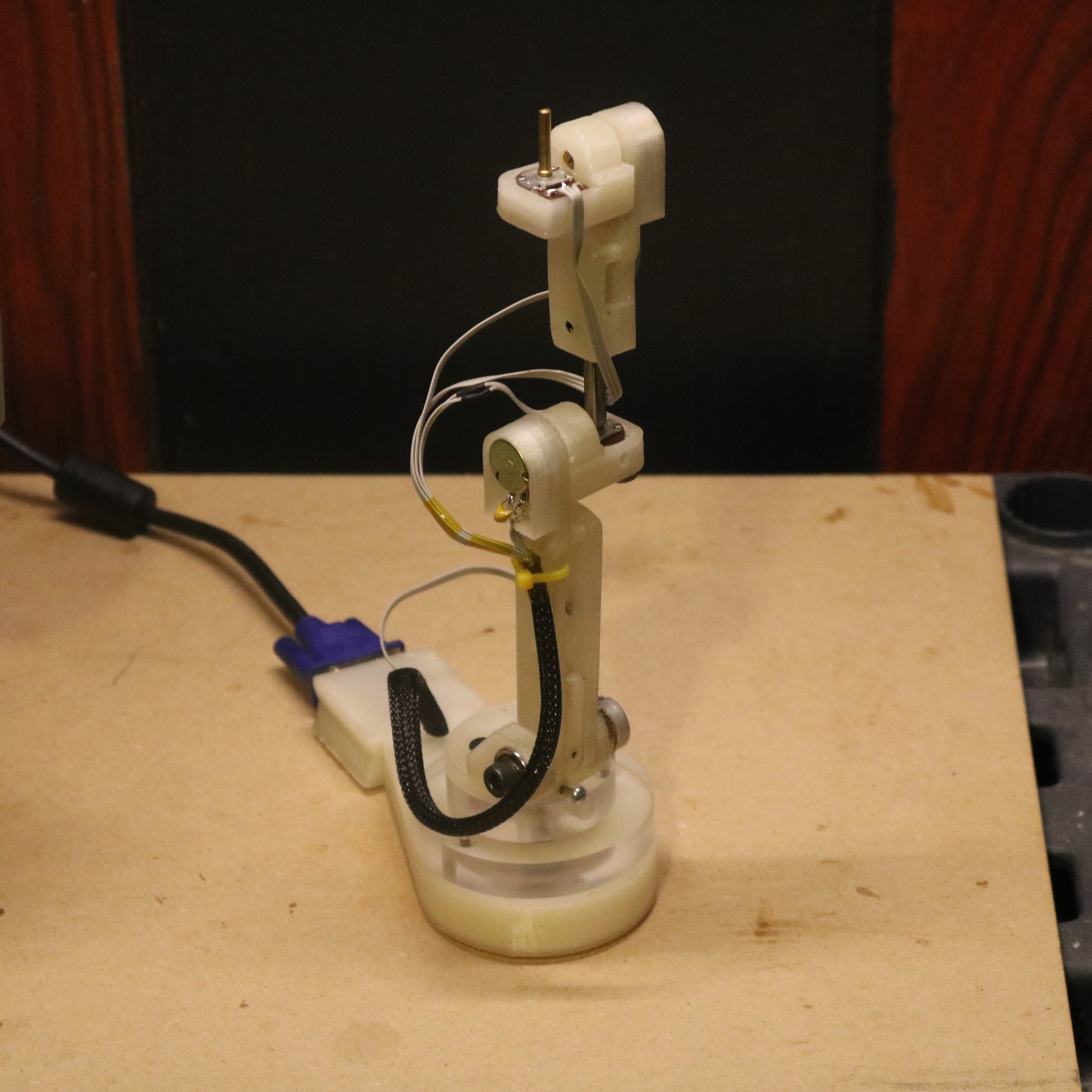
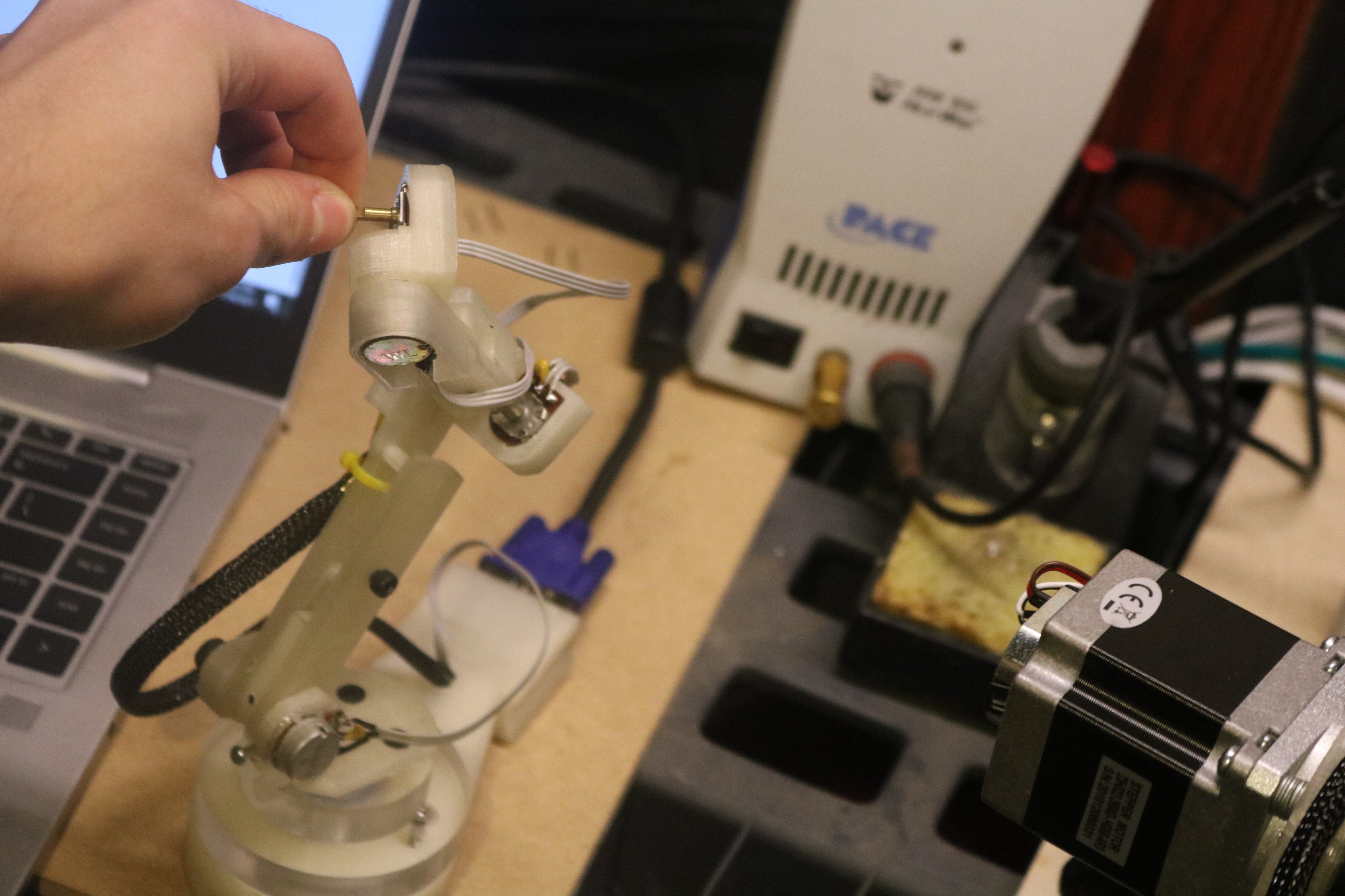
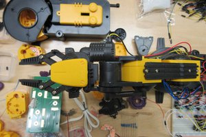
Controller Arm
An early version of the controller arm is shown below. The device connects to the electronics enclosure via a VGA cable. Each joint rotates about a 10k rotary potentiometer which acts as a position sensor. The kinematic structure of the controller arm is congruent to the robot arm, at approximately 1/3 scale. Each pot acts as a voltage divider and provides an analog voltage for the Teensy to interpret. With full positional and orientationally freedom, users can move the tip of the controller in any direction, and the robotic arm will match the movements in a proportional manner.

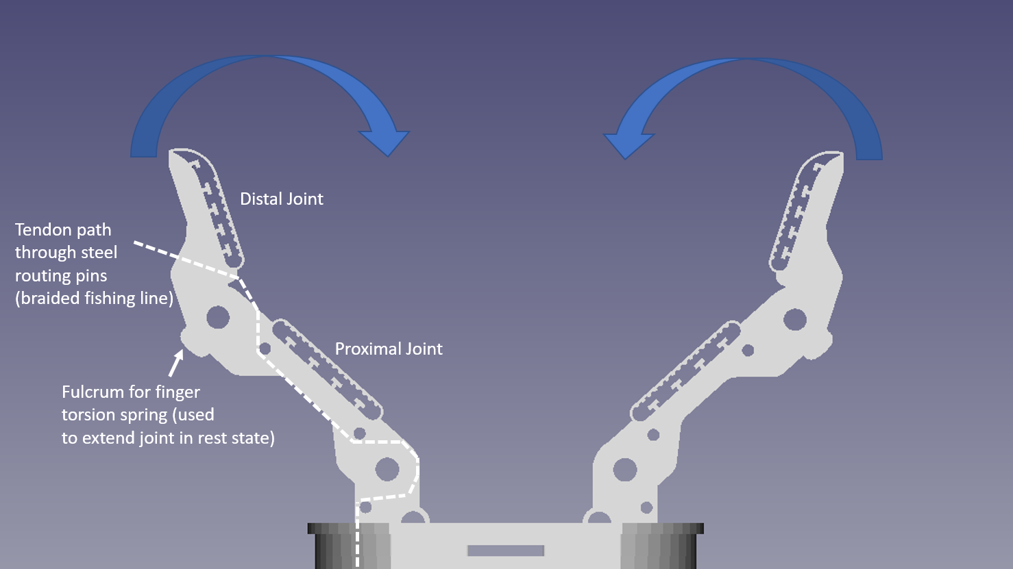
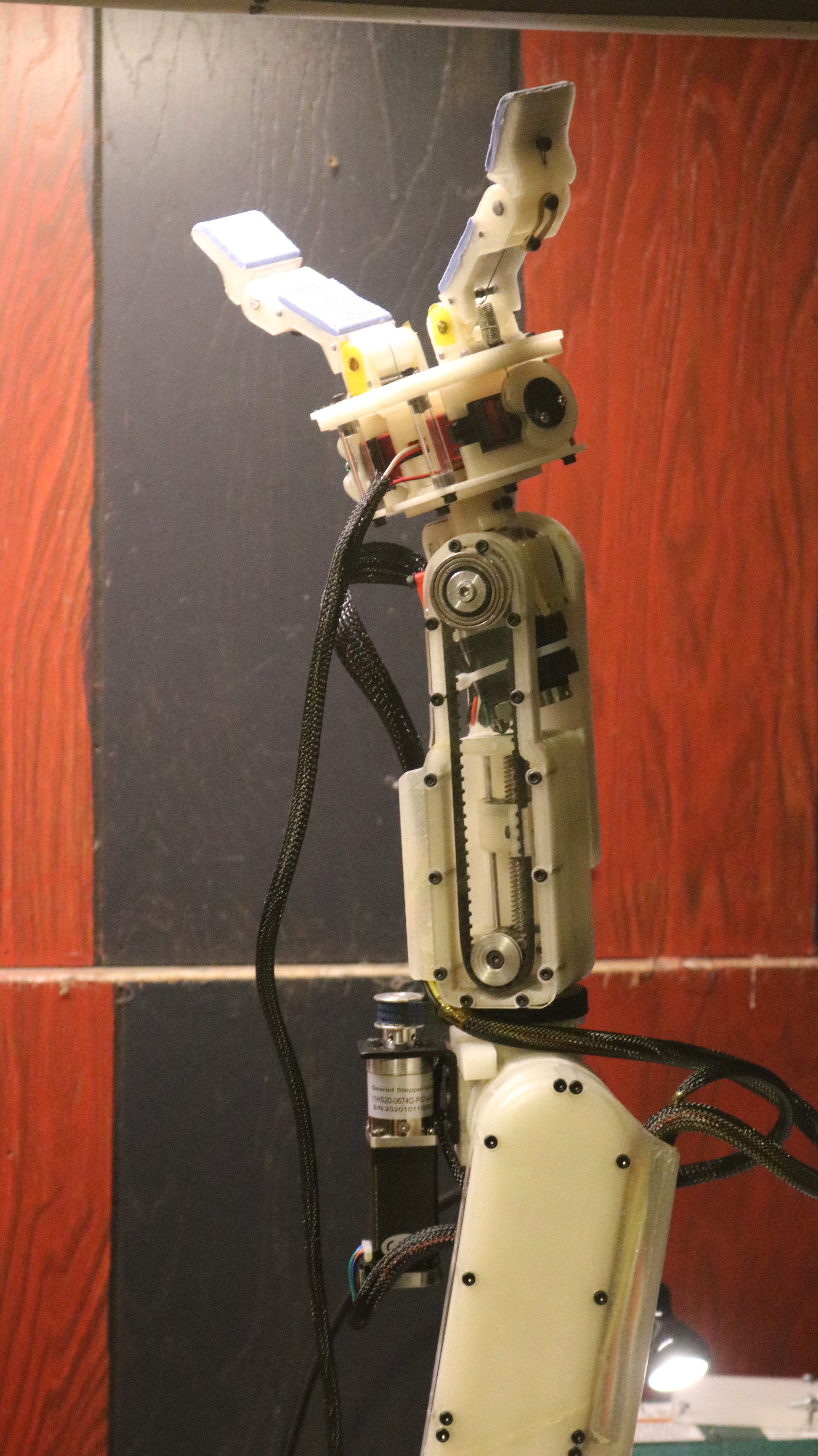
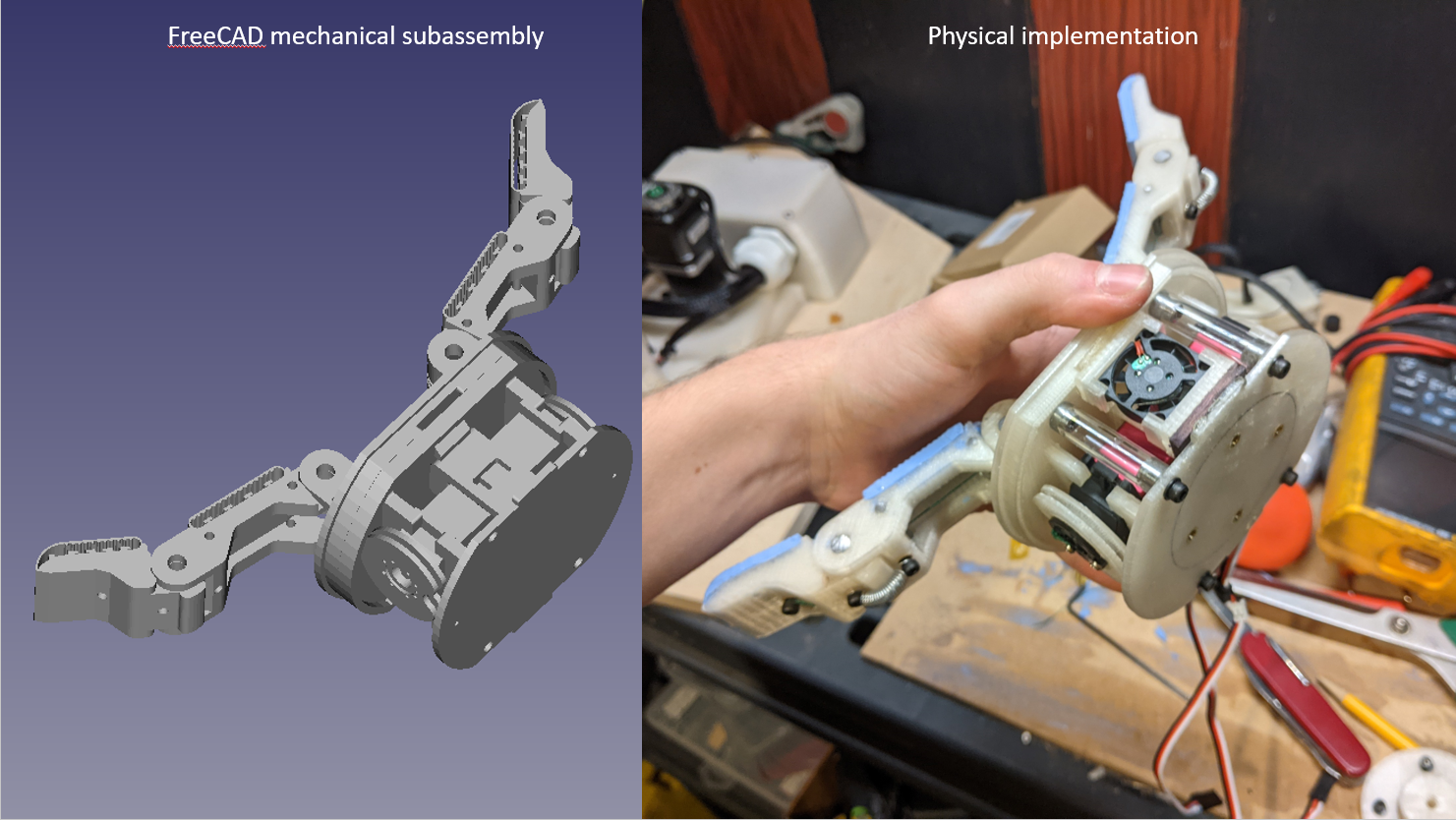
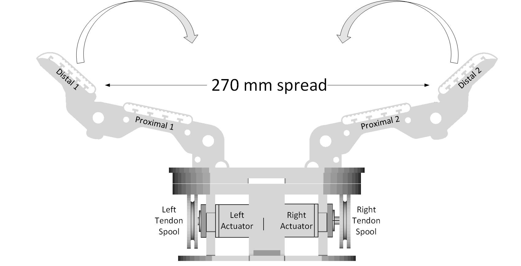
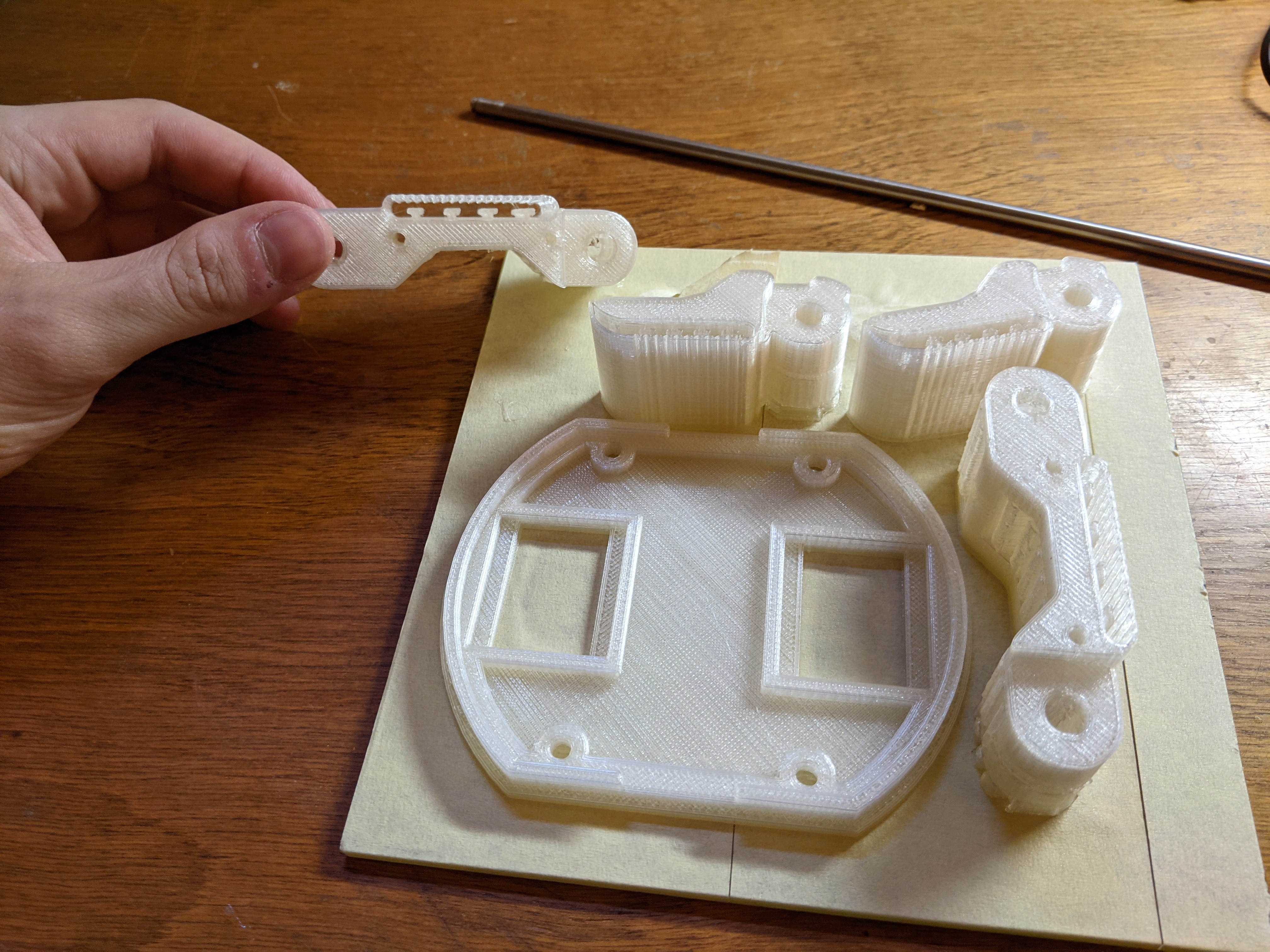
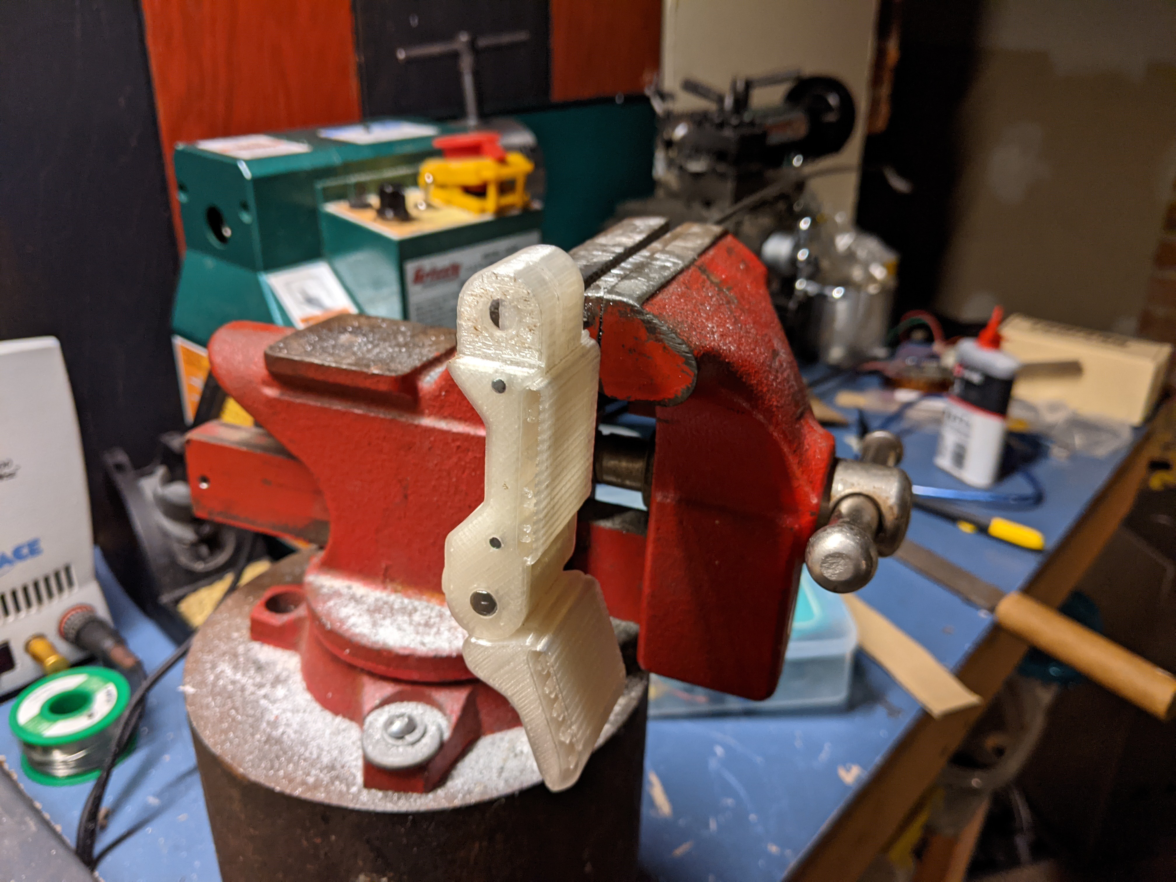
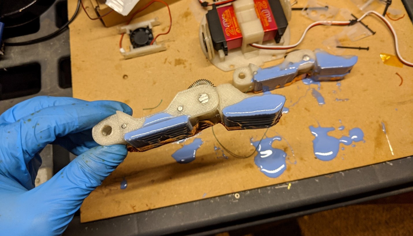
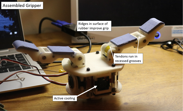
Two Finger Hand

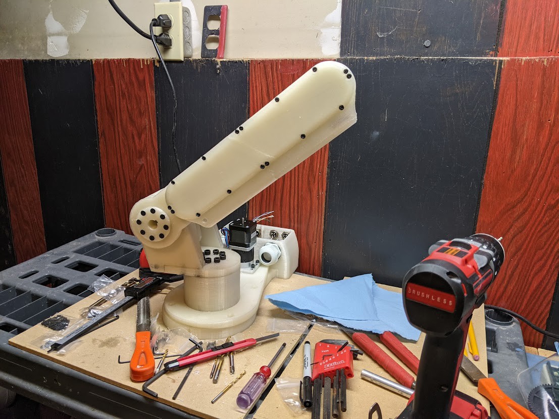
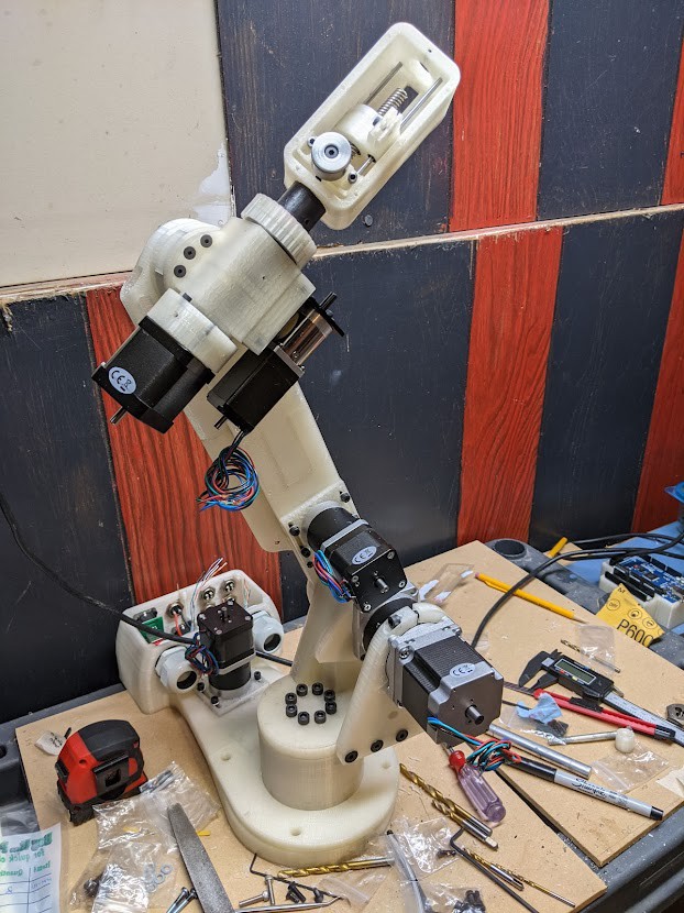
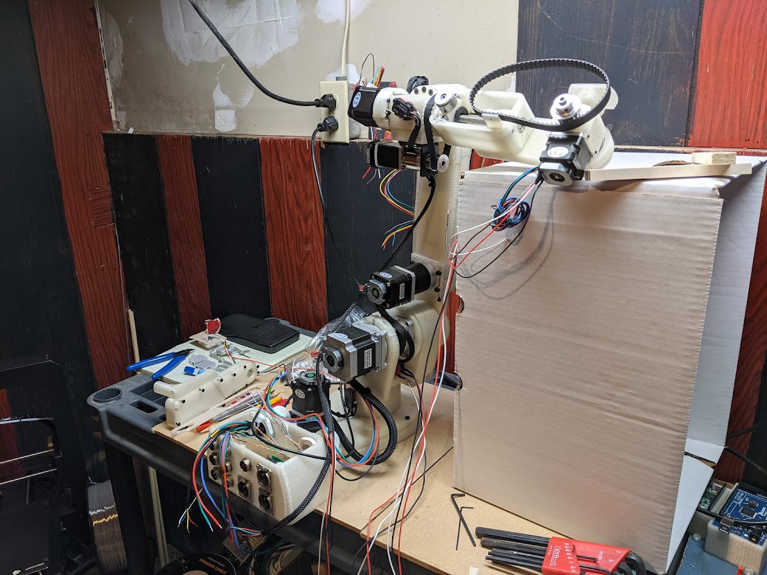
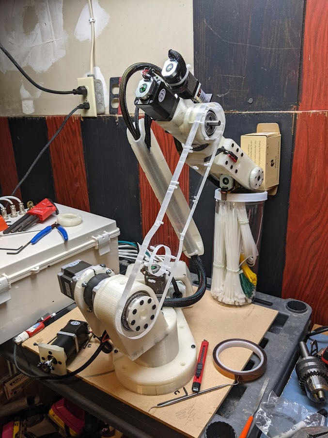
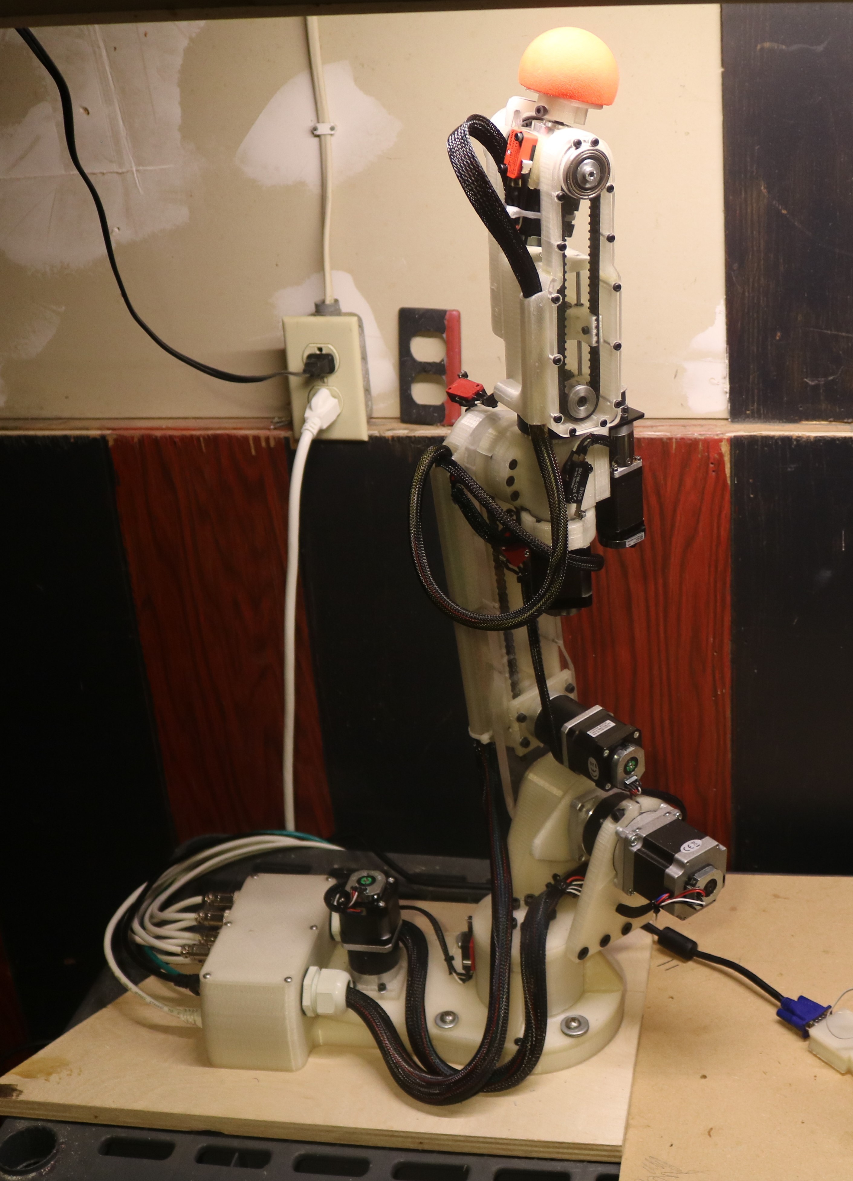
Robotic Arm
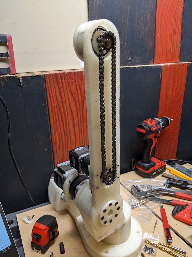
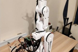
The design of the robotic arm used in this project is based on the Annin AR3 industrial arm, an open-source robotics platform. More information regarding this project can be found here. This is an ongoing project with detailed specifications on motor sizes, hardware, fasteners, etc.
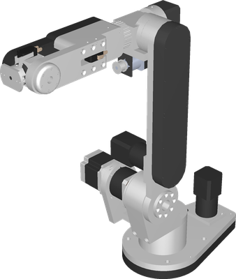
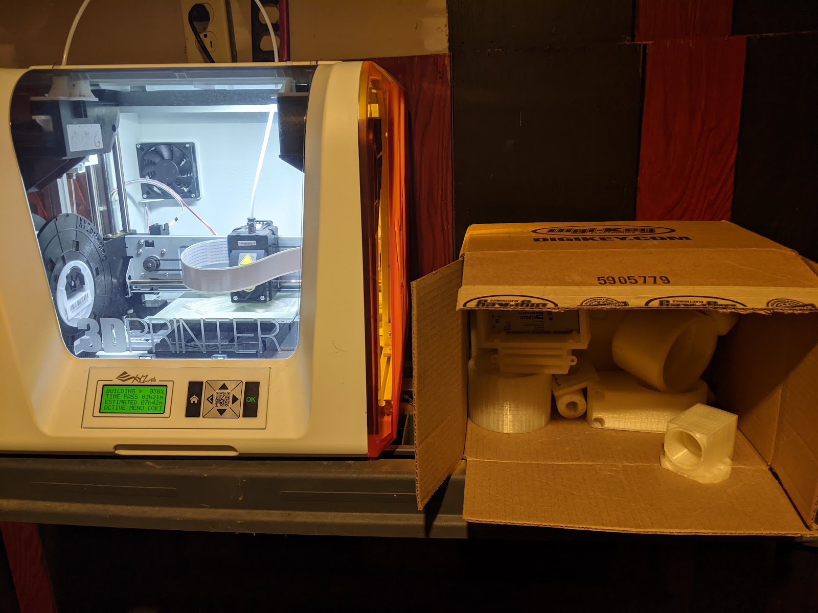
One significant modification to the original design was that I manufactured nearly every component from plastic. There are several reasons why I chose to do this. It is much simpler to machine plastic parts, and building the arm during Covid restricted my access to large equipment that would be necessary to produce an aluminum system. Secondly, a plastic-based robot has generally reduced rigidity, weight and increased compliance compared to aluminum construction. All of these attributes are favorable in application of a collaborative robot (COBOT) where human safety is the top priority.
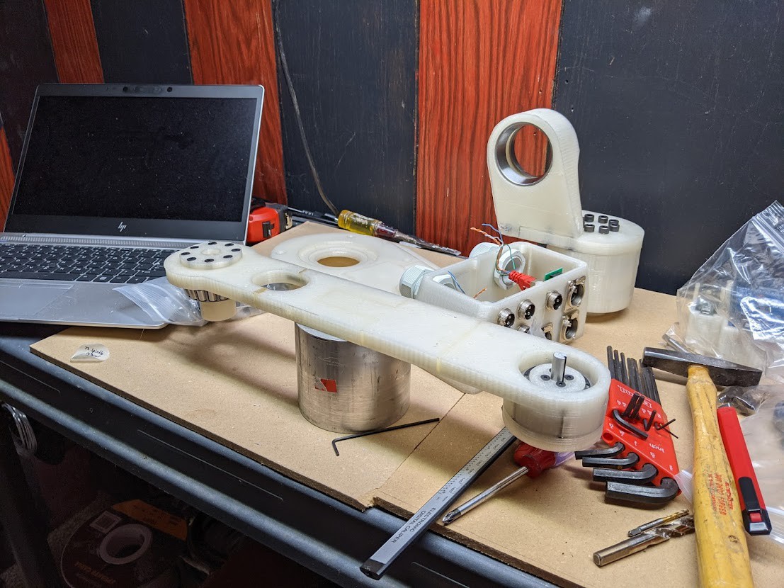
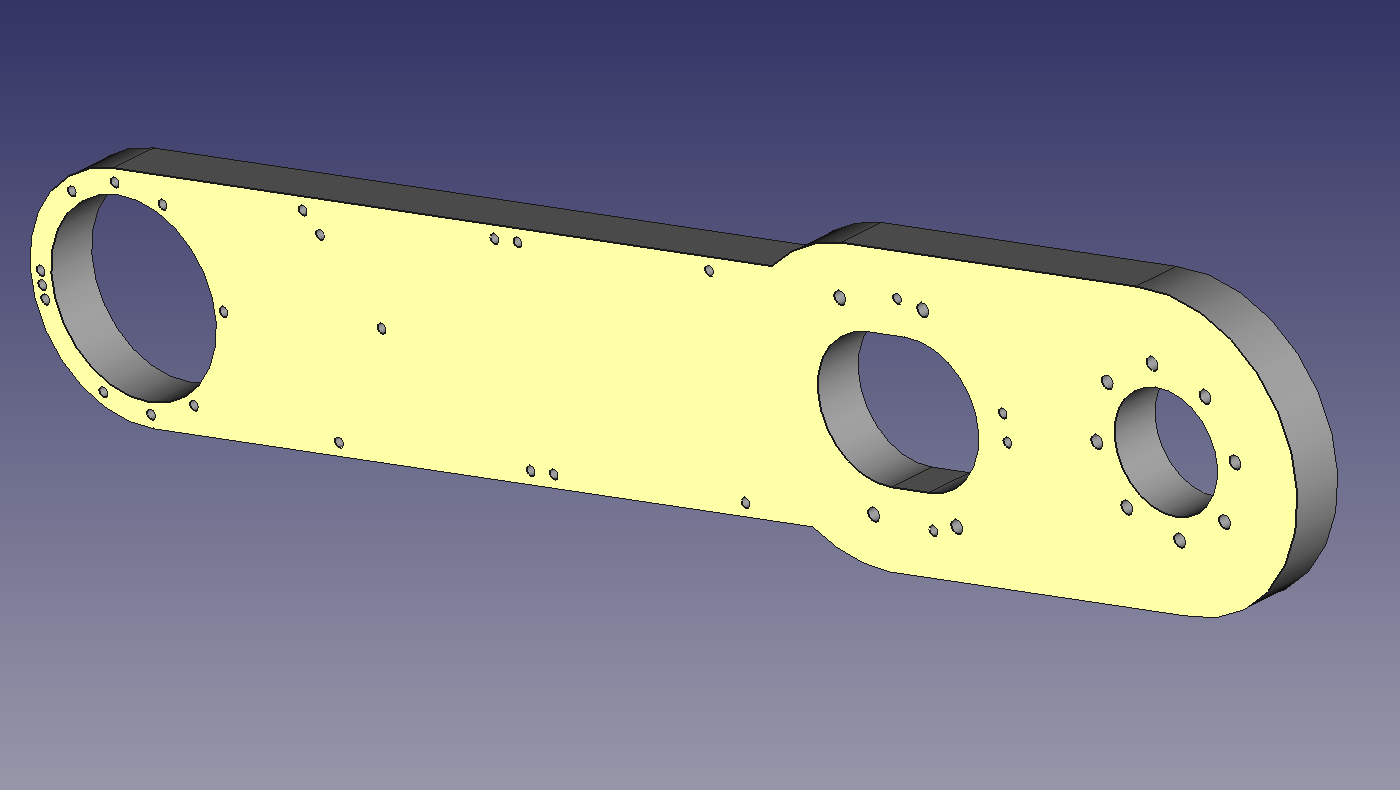
Additionally, I redesigned the J2 arm, adding additional support and lowering the location of the J3 motor.

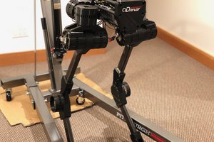
The specifications for this arm (weight, payload, reach, DOF, etc.) are very similar to the JACO ™...
Read more »
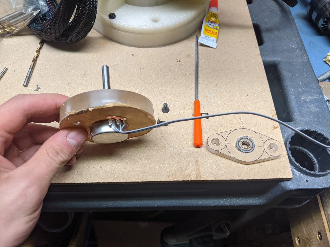
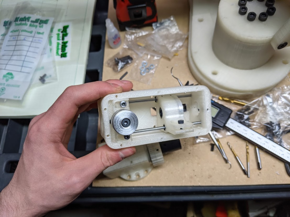
 Setting tapered roller bearing seats into the J1 and J2 turret housings.
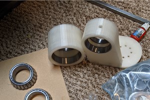

 Kenji Larsen
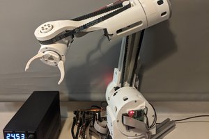
 Petar Crnjak
Great project! Your work is very impressive.