 Open Technology
Step 1: Open any of your favourite Arduino projects
In this example, let us use the Arduino simulator project which has the OLED display and software from Adafruit. The link is here.
Step2: Add Wokwi Logic Analyser to your project
adding the parts to the Wokwi Simulation is very easy. Just click on the purple Plus icon and select the Logic analyser part

Once you add the logic analyser, your project should look something like below

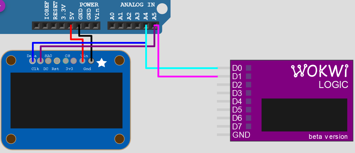
You have to make the connections first. In this example, you only need two pins to be monitored. I2C data line and I2C clock line. Let us use the D0 and D1 pins of the logic analyser to I2C lines. Make the connection as follows
- D0 - I2C SDA - I2C dataline
- D1 - I2C SCL - I2C Clock line
- GND - Arduino UNO GND
After the connection, your circuit should look something like the below image. With this step, you have completed the connection of Logic Analyser to the I2C lines on the Arduino simulator from Wokwi.
Step3: Recording the data on Wokwi Logic Analyser
Once, the connections are made, there is nothing much to do. This will work straightaway. all you have to do is, run the simulation for the duration you need. The Wokwi module will keep showing the number of samples captured. The below image shows a short animation of a logic analyser showing a number of samples captured, and once you stop the simulation, how the file gets downloaded automatically.
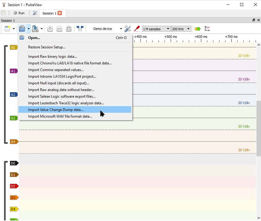
Step4: Open the ".vcd" file in the pulse view software
The Pulseview software is free and easy to use. Once you have downloaded the pulseview software, open the application. Click on the "open" icon and select the file format as "Import Value Change Data".
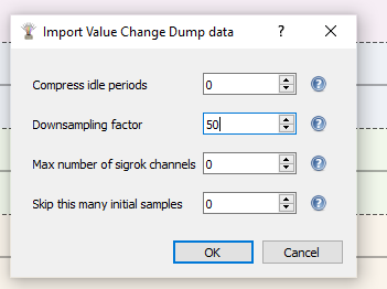
Next, depending on the type of data you are viewing, you can easily set the appropriate sampling rate needed. This will help you and your computer to load the data faster still not lose the data. For this example, the Downsampling factor to 50. This is sufficient for the I2C data you are viewing.
Here is the view of the I2C data.
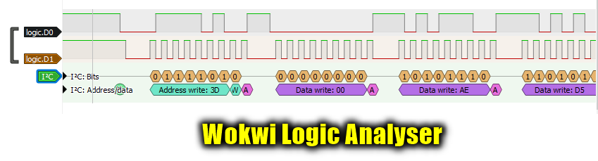
The above image shows the capability of the Wokwi Arduino simulator as well as the pulseview software to together provide you with the opportunity to see what is happening on the lines. This can be I2C, SPI or even bit-banging using GPIO. This is an awesome feature to get hands-on what is happening on the wires without real hardware. I hope you have now got a good hint of setting up the logic analyser for your next Arduino simulator project on the Wokwi Arduino simulator.

 Manuel
 José Miguel Díaz
 Xiyuan
 Ryan Michaud