 Manuel Tosone
Assembling
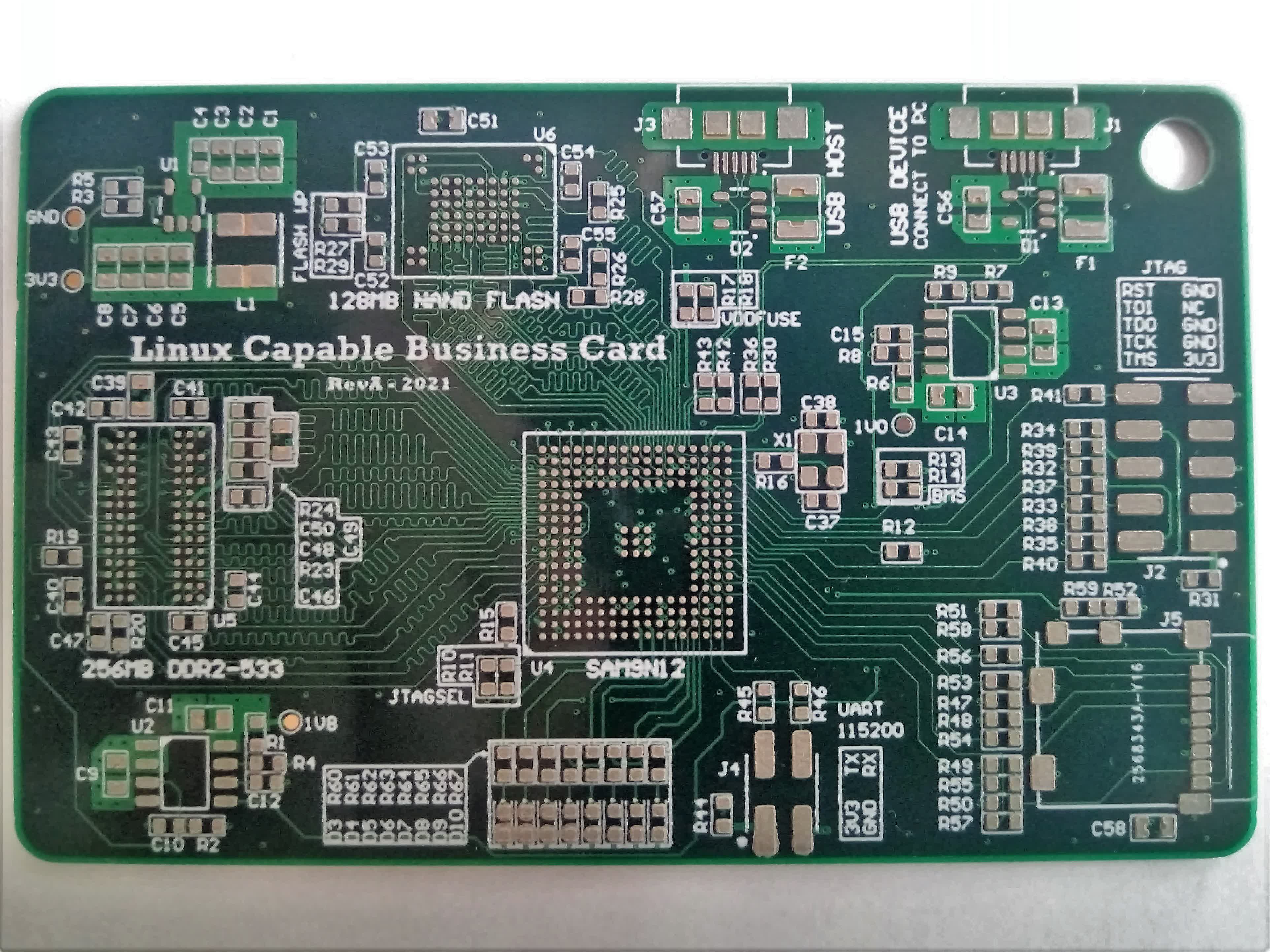
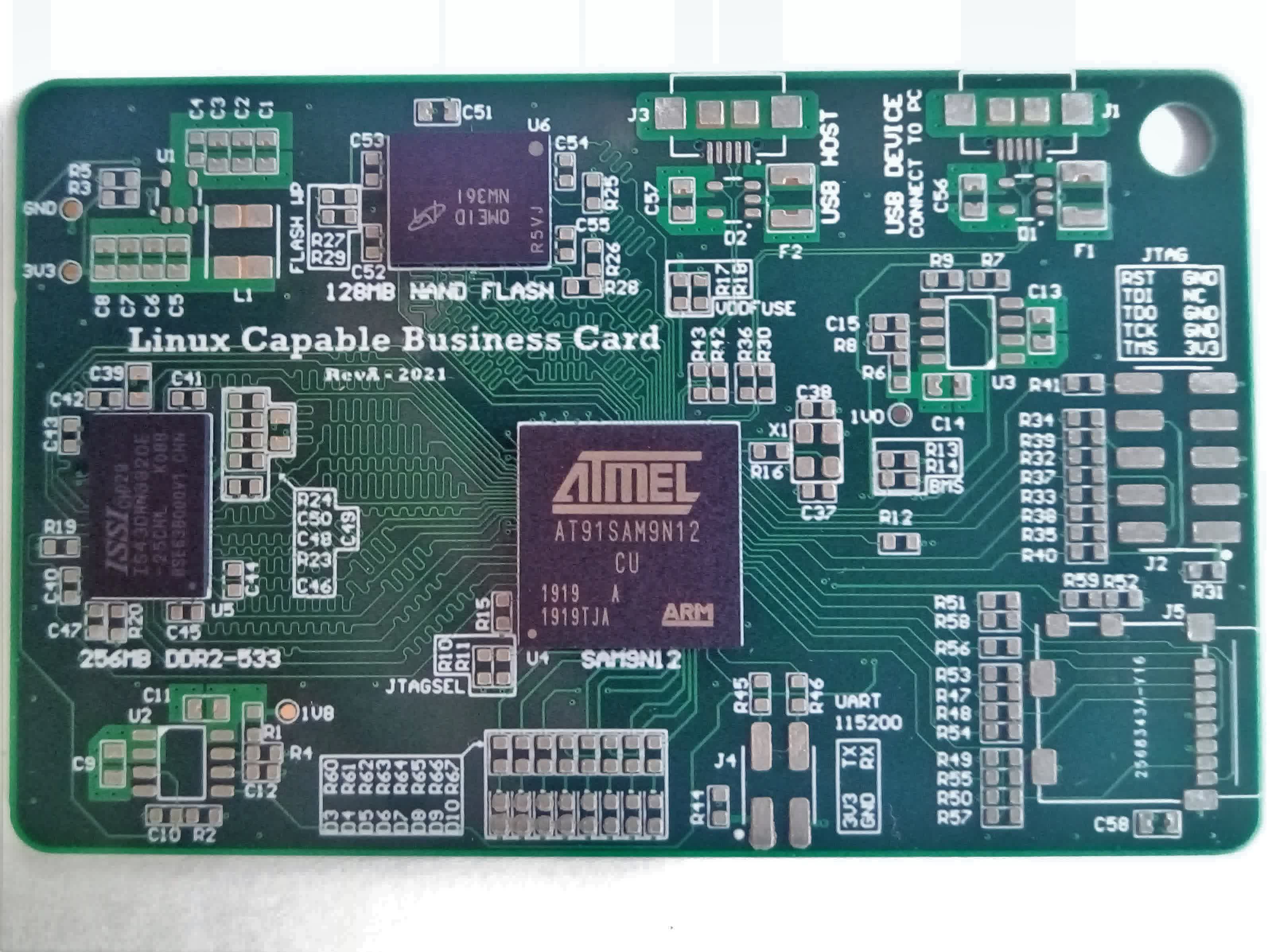
The board is hand-assembled. I use a stencil to spread the solder paste and then the components are placed with tweezers. When working with BGA packages I always place them first. To check the alignment, I look under the package from its side, If I can see light in between every row the component is aligned. Using a thicker paste it is possible to tweak the position of the package by bumping it from the side without smearing the paste. When the component is in place I lightly push down on it to make sure every ball is in contact with the paste. At this stage, If I screw up the placement, I can always clean the board and start over with minimal drama. When all the BGAs are in place, I position the other components starting with the hardest. Soldering is done with hot air. Managing the heat is a little tricky, mostly because it's hard to tell when the BGAs are soldered properly. What works for me, is to set the temperature to 100 °C and preheat the entire board for about two minutes, then I increase the temperature and start reflowing component by component.
 |  |  |

First Power Up
Applying power for the first time is always a little scary.
First, with a multimeter, I checked every power rail for shorts. Next, I connected the board to a current limited power supply and measured the voltages on the tree test points. The voltages were good. There is a sequence in which the power rails must come up to ensure proper operation. The correct order is 3v3, 1V8, 1V0, with the CPU reset releasing last. Looking at the scope capture below we see that it is correct.

The last check is to see if the oscillator is running, and it is. That's promising, we might have a working board!

Linux kernel and Buildroot
I'm no expert when it comes to embedded Linux. Since this is my first time using buildroot to compile Linux from scratch, I won't try to explain how it works (I barely understand it myself ;) ) but I will link to some good resources in case you want to learn more.
- Buildroot - Create a Custom Project - https://microchipdeveloper.com/32mpu:buildroot-custom-project
- AT91Bootstrap - https://www.linux4sam.org/bin/view/Linux4SAM/AT91Bootstrap4
- Making embedded Linux computer - https://hforsten.com/making-embedded-linux-computer.html
- Mastering Embedded Linux - https://www.thirtythreeforty.net/posts/2020/01/mastering-embedded-linux-part-3-buildroot/
- Embedded Linux System - https://brainyv2.hak8or.com/
To keep things simple I've decided to have the second stage bootloader loading Linux directly instead of using a third stage like u-boot.
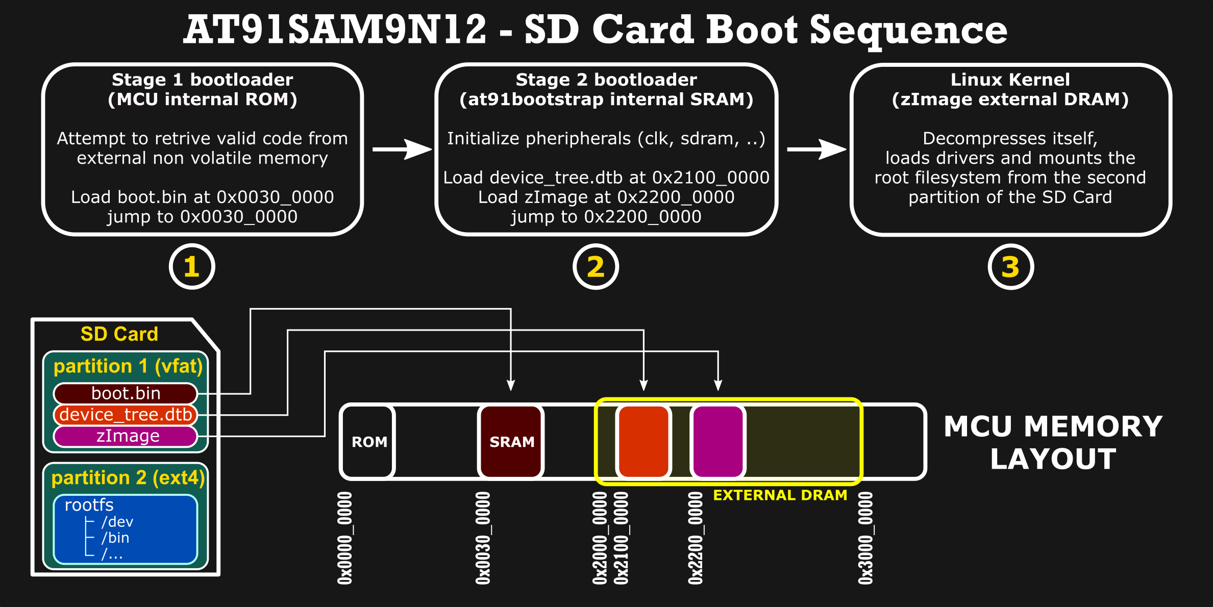
The boot process starts with the first stage bootloader that resides in the internal ROM. It tries to load valid code from external non-volatile memories. When booting from the SD Card it looks for a “boot.bin” file (second stage bootloader) in the root directory of a FAT12/16/32 partition. That file is copied to the internal SRAM and executed.
The second stage bootloader initializes the hardware, loads the device tree and kernel image to the external DRAM. After that jumps to the kernel image that is self-extracting (it decompresses itself inside the memory). Then the kernel loads the root file system from the second partition of the SD Card.
RAM Troubleshooting
After putting the image on the SD Card and connecting to the debug serial port, I applied power through the USB. The board Initially seemed to work fine, the SD card was detected, the second stage bootloader was able to run and load the kernel. It was all fine until the MPU started executing code from the external DRAM, there was some text output from the kernel but then it just kernel panic and gave up trying. On subsequent attempts it didn't behave consistently, the system did freeze or kernel panic at different times. After enough tries, it managed to boot and I was able to log in, from the terminal I tried to run memtester (userspace tester for stress-testing the memory subsystem) and it confirmed there were some issues.
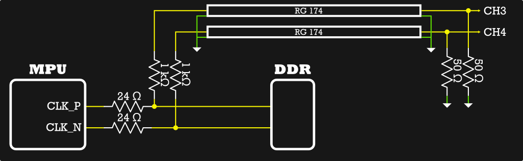
I immediately began thinking there were some timing issues or the DRAM controller wasn't initialized properly. Before going crazy trying to understand how the DRAM controller is initialized, I decided to check that at least the clock has the right frequency. The clock for the memory should be 133MHz. To probe the differential clock signals, I connected the oscilloscope with two equal-length sections of coaxial cable, terminated to 50 Ohm at the scope, and connected through 1 KOhm resistors to the test points. This setup makes a 21:1 probe that's better for measuring differential signals than using two 10x probes. The high-frequency compensating adjustments, as well as the DC gain of the two probes, must match perfectly. That's difficult to achieve with 10x probes, plus it is easier to solder two resistors and some coaxial cable than it is to hold the probes in place while operating the scope and playing with the board.
The scope capture below shows the differential signals superimposed, with color grading turned on and 1-second persistence. The bottom trace is the differential signal computed with the math function of the oscilloscope.
The frequency is correct but what about all this jitter? I'm triggering the scope from one of the two clock signals with the delay on the timebase set to 20 uS. Mind you that with this trigger setup the displayed jitter is double the actual one. It's interesting to see that the jitter increases when the processor is under load. I think this is a result of the lack of filtering on the PLL power supply pins. Trying to keep the design simple, I didn't include a ferrite bead or additional filtering.
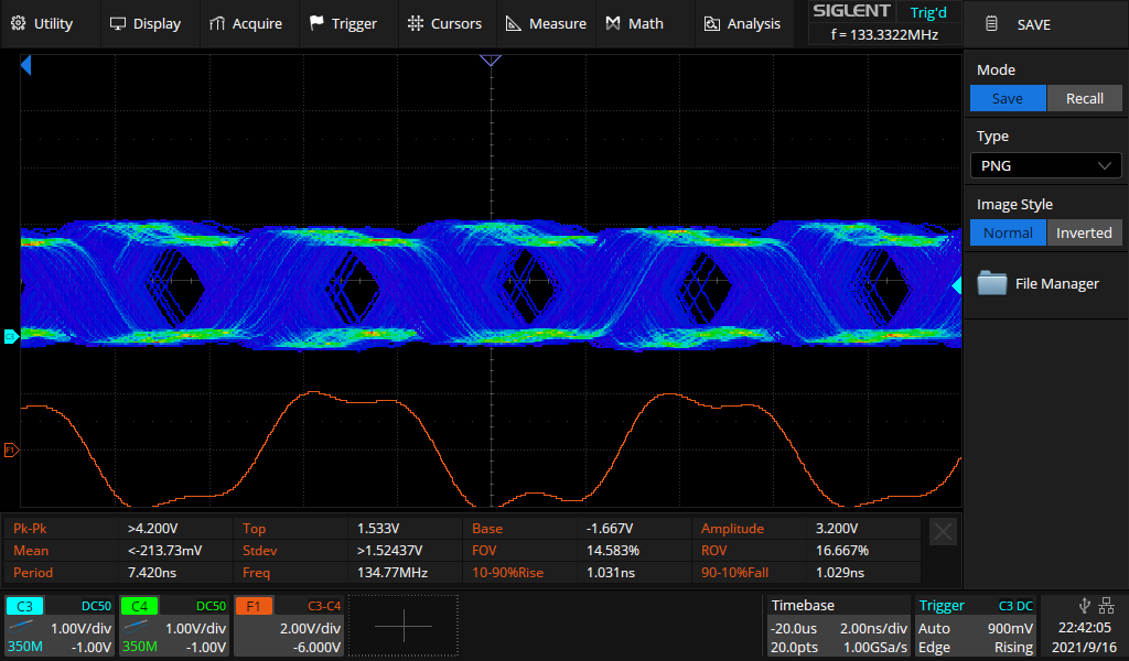 133 Mhz clock at idle | 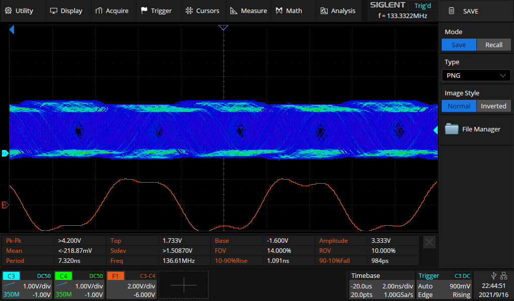 133 MHz clock under load |
Next, I've tried lowering the clock frequency to 100MHz. The board booted on the first try and memtester didn't found any issues.
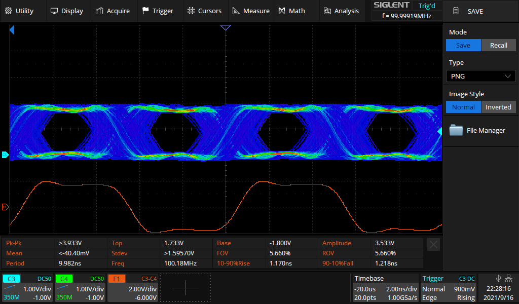 100 MHz clock at idle | 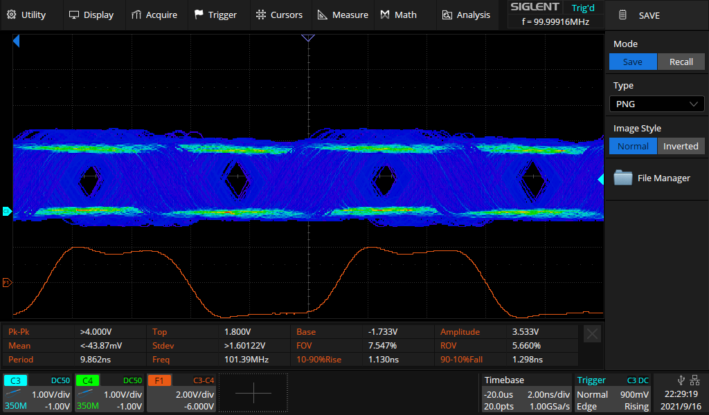 100 MHz clock under load |
Done with the measurements I've disconnected the probes and the board started behaving erratically as before. Actually wasn't lowering the frequency that fixed the problem but the loading from the probes. In the end, I soldered a 10 pF capacitor across the differential signals. I even try to raise the clock frequency and the board now works perfectly fine at 133 MHz RAM clock and 399MHz CPU clock.

Demo
What follows is a demo of the board booting Linux from the SD card. The video is not sped up, it boots in 6 seconds!
Discussions
Become a Hackaday.io Member
Create an account to leave a comment. Already have an account? Log In.