A common problem for sticks with Arduinos / Teensy as controllers is the the limited number of pins.
Since I am using the teensy board I will talk about it. As you can see on the pinout https://www.pjrc.com/teensy/pinout.html the teensy 4 has 10 analog and 14 digital pins - where the analog pins can be used as digital pins as well.
For my current setup there are:
- 2 x 3 axis sticks and one 2 axis stick plus an analog slide potentiometer -> 9 analog inputs
- 10 arcade buttons and 8 switches a rotary encoder with a button -> 20 digital inputs
By using simple arithmetic ;-) it is easy to see that this will not work by directly wiring every input to a pin on the teensy.
There are 2 common approaches for the button problem:
- a button matrix
- a multiplexer
The Matrix
There are tons of excellent articles about the button matrix and a matrix button pad is included in most Arduino starter kits - so I will not cover all the details. Basically it looks like this
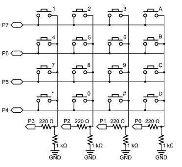
you wire the buttons in a matrix. In the above example the columns are used as outputs -> voltage supplied to them and the rows are inputs.
The code steps through all the output pins (columns) and reads the values on the input pins. Some would call his this method multiplexing ;)
As far as I know there are also libraries available for Arduino which to most of the magic for you with debounce and everything. For my 20 digital pins I could have used a 5 by 4 matrix -> 9 pins for 20 inputs is a good deal.
Further more there is no way to multiplex analog inputs from potentiometers - although this would not have been a a problem in my use case.
But soldering this matrix in the actual stick seemed a bit annoying to me... ;). So I dropped this approach.
The (hardware) multiplexer
a good alternative for a guy with mediocre solder skills like me is a hardware multiplexer where all the wiring is happening in an IC. The CD74HC4067 chip was the solution for me. it looks like this:
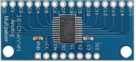
Its a 16 channel multiplexer (C0 to C15 in the picture). 16 decimal needs 4 bits to address (S0 to S3) and one signal pin to read the current input (SIG). This means you can read 16 inputs by utilizing 5 pins on your board. The code maybe a bit harder to read but the soldering is straight forward. One pin of the arcade buttons all to ground and the other one straight to the channel of the multiplexer. Where I decided to not directly solder the cables to the multiplexer - used dupont connectors to be a bit more flexible. This looked something like this in my stage 2 model
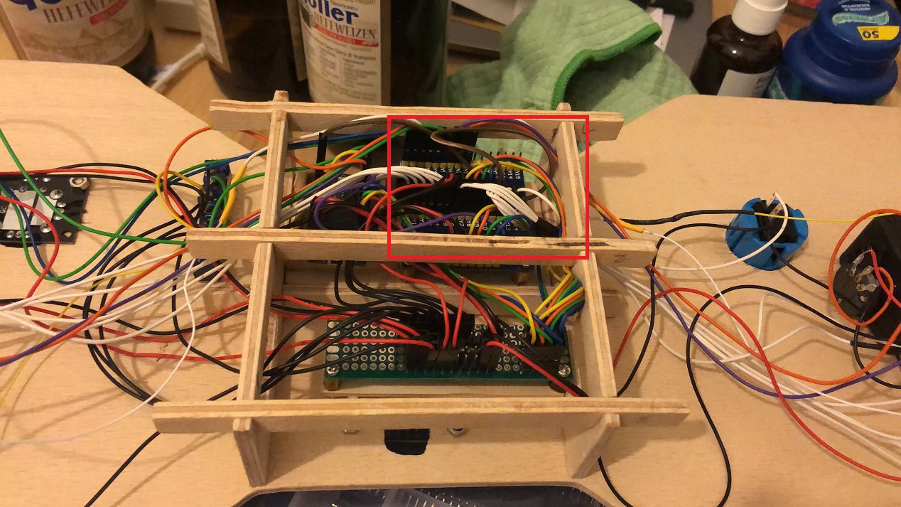
The red square are the 2 multiplexers ( one for buttons, one for analog sticks) and all the white cables are the button inputs.
I will give a instruction on how the code was implemented to use the multiplexers for a joystick later on
Hope you found this interesting :-)
Discussions
Become a Hackaday.io Member
Create an account to leave a comment. Already have an account? Log In.